EP0443494A2 - Bilderzeugungsvorrichtung - Google Patents
Bilderzeugungsvorrichtung Download PDFInfo
- Publication number
- EP0443494A2 EP0443494A2 EP91102279A EP91102279A EP0443494A2 EP 0443494 A2 EP0443494 A2 EP 0443494A2 EP 91102279 A EP91102279 A EP 91102279A EP 91102279 A EP91102279 A EP 91102279A EP 0443494 A2 EP0443494 A2 EP 0443494A2
- Authority
- EP
- European Patent Office
- Prior art keywords
- paper feed
- image
- image forming
- recording medium
- forming unit
- Prior art date
- Legal status (The legal status is an assumption and is not a legal conclusion. Google has not performed a legal analysis and makes no representation as to the accuracy of the status listed.)
- Granted
Links
Images



















Classifications
-
- G—PHYSICS
- G06—COMPUTING OR CALCULATING; COUNTING
- G06K—GRAPHICAL DATA READING; PRESENTATION OF DATA; RECORD CARRIERS; HANDLING RECORD CARRIERS
- G06K15/00—Arrangements for producing a permanent visual presentation of the output data, e.g. computer output printers
- G06K15/02—Arrangements for producing a permanent visual presentation of the output data, e.g. computer output printers using printers
- G06K15/12—Arrangements for producing a permanent visual presentation of the output data, e.g. computer output printers using printers by photographic printing, e.g. by laser printers
- G06K15/128—Arrangements for producing a permanent visual presentation of the output data, e.g. computer output printers using printers by photographic printing, e.g. by laser printers generating or processing printable items, e.g. characters
-
- G—PHYSICS
- G06—COMPUTING OR CALCULATING; COUNTING
- G06K—GRAPHICAL DATA READING; PRESENTATION OF DATA; RECORD CARRIERS; HANDLING RECORD CARRIERS
- G06K15/00—Arrangements for producing a permanent visual presentation of the output data, e.g. computer output printers
- G06K15/02—Arrangements for producing a permanent visual presentation of the output data, e.g. computer output printers using printers
- G06K15/16—Means for paper feeding or form feeding
Definitions
- the present invention relates to an image forming apparatus such as an electrophotographic printer apparatus having, e.g., a spare paper feed function.
- the spare paper feed function is defined as a function of feeding a recording sheet or the like from a paper feed cassette or the like to a predetermined position prior to a print request (or an end of one-page image development), and feeding the paper sheet from the predetermined position to a recording unit upon reception of a print request.
- a conventional image forming apparatus such as a laser printer performs predetermined image formation in accordance with a recording request signal ( PRINT ), a vertical sync request signal ( VSREQ ), a vertical sync signal ( VSYNC ), and an image signal ( VDO ).
- Fig. 1 shows a schematic arrangement of a laser printer
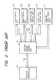
- Fig. 2 is a block diagram of its controller
- Fig. 3 is a timing chart showing a recording operation of the laser printer.
- a printer controller 100 develops an image on the basis of code data from an external host computer (not shown) or the like and outputs the signal PRINT when bit map image data of one page is obtained.
- a paper feed roller 49 starts to feed a sheet to a resist roller 50 in accordance with the signal PRINT from the printer controller 100.
- a printer engine control unit 101 supplies the signal VSREQ to the printer controller 100 at a predetermined timing when a resist sensor 51 detects a leading end of the recording medium.
- the printer controller 100 immediately outputs the signal VSYNC and causes a semiconductor laser (not shown) to emit laser light 46, thereby starting exposure. In synchronism with the exposure operation, the resist roller 50 is driven, and the recording medium is fed toward a photosensitive drum 41.
- a developing unit 43 develops a latent image formed on the photosensitive drum 41 to form a toner image.
- the toner image formed on the photosensitive drum 41 is transferred to a recording medium by a transfer roller 44 and is fixed on the recording medium by a fixing roller 48.
- a charge roller 42 uniformly charges the photosensitive drum 41.
- a cleaner 45 removes a toner left on the photosensitive drum 41.
- a polygonal mirror 47 scans the laser light 46 in a direction perpendicular to the drawing surface.
- a recording mode of the already fed recording medium by the user cannot be changed upon start of the paper feed operation.
- a recording mode must be determined prior to generation of the signal PRINT .
- the print enable state cannot be effective unless the fed recording medium is discharged.
- a throughput is undesirably decreased, and the recording medium is wastefully discharged.
- the printer controller 100 outputs a spare paper feed request signal for informing spare paper feeding to the printer engine control unit 101 prior to the end of image development of one page.
- the control unit 101 controls a paper feed control unit 105 to stop, e.g., a recording medium in a state wherein it abuts against the resist roller 50.
- the printer engine control unit 101 waits for a print request signal from the printer controller 100. The following operations are the same as described above.
- An abnormal event handle unit 111 monitors a state of the inside of the printer and alarms an abnormal event to the printer engine control unit 101 when the abnormal event which causes failure of normal print processing occurs.
- the abnormal event handle unit 111 does not distinguish abnormal event handling for an abnormal event occurring during printing while a print request signal is received from the printer controller 100 from abnormal even handling for an abnormal event during paper feeding upon reception of a spare paper feed request. Therefore, the abnormal even handle unit 111 performs single processing.
- a print request from the printer controller 100 Upon reception of a print request from the printer controller 100, the paper sheet is fed to the resist roller 50 by driving of the paper feed roller. At this time, a vertical sync request signal is output to the printer controller 100. Upon reception of the vertical sync signal from the printer controller 100, an image data output instruction is output to an image control unit 103. At the same time, a timer for measuring a paper feed timing of the next page is started. When the time set in the timer has elapsed and if a print request for the next page is not present, the in-print sheet is discharged and the feed system is stopped. However, if the print request is present, a paper feed instruction for the next page is output.
- the paper sheet is not fed and stopped upon reception of the print request in abnormal event handling. That is, assume that a spare paper is fed upon reception of a spare paper feed request, that the paper sheet is fed to a predetermined position, i.e., the resist position, and that the apparatus waits for a print request. Under these conditions, when the cassette is temporarily removed and a print request is received after the cassette is then mounted again, the normal vertical sync request is output because the cassette is present at this time. Upon reception of the vertical sync signal, an image data output instruction is output.
- the sheet in spare paper feeding receives a deformation force by a loop, a nip of the resist roller 50, and a pressure of the paper feed roller 49.
- the recording medium is exemplified by a thin sheet such as normal paper, intermediate sensitized paper, an OHP film, synthetic paper, an envelope.
- a thin sheet such as normal paper, intermediate sensitized paper, an OHP film, synthetic paper, an envelope.
- the curled portion is not properly brought into contact with the photosensitive drum during image transfer, thus causing a transfer error. More specifically, a white omission occurs because the toner is not locally transferred to the sheet. In addition, since the image is transferred to the sheet while it is not properly brought into contact, image blurring occurs, thereby degrading recording image quality.
- the following problem occurs in an image forming apparatus having a spare paper feed function when one of a plurality of paper feed means is designated to feed a recording medium.
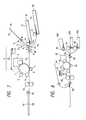
- Fig. 7 shows a schematic arrangement of a laser beam printer having a plurality of paper feed means.
- An electrophotographic photosensitive drum 1 is rotated at a predetermined peripheral velocity (process speed) clockwise, i.e., a direction indicated by an arrow.
- the photosensitive drum 1 is uniformly charged to a predetermined polarity at a predetermined potential by a charge roller serving as a charging means during rotation.
- the charged surface of the photosensitive drum 1 receives laser beam scanning exposure light L (image write) by a laser scanner 5 which includes a laser oscillator, a polygonal scanner, and an optical element and which outputs a laser beam modulated in correspondence with a target time-series electrical digital pixels signal input from a host apparatus (not shown) such as a computer or a wordprocessor to a controller (not shown).
- a host apparatus such as a computer or a wordprocessor to a controller (not shown).
- a latent image corresponding to the target image information is formed on the circumferential surface of the photosensitive drum 1.
- the latent image on the drum surface is visualized by a developing unit 3 into a toner image.
- the toner image reaches a transfer portion B as an opposite portion between a transfer roller 4 and the drum 1 during rotation of the drum 1.
- the toner image is continuously transferred from the photosensitive drum 1 to a recording sheet fed from a sheet material feed unit (to be described later) to the transfer portion B at a predetermined timing determined by a resist roller 9.
- the recording sheet to which the toner image is transferred is separated from the surface of the photosensitive drum 1 and is fed to a fixer 12.
- the image is fixed on the sheet, and the sheet as an image formation product (print) S4 is discharged to a paper discharge tray 20 by a paper discharge roller 19.
- the surface of the drum 1 which passed the transfer portion B is subjected to removal or cleaning of a residual pile such as a residual toner by a cleaner 6 and is repeatedly used for image formation.
- the sheet material feed units are constituted by the following three paper feed means:
- a printer engine When a printer engine (not shown) receives a print signal from a controller, the printer engine operates a preselected one of the three paper feed means 31 to 33 to feed a sheet. More specifically,
- the recording sheet S2 must be fed from the paper feed position to the predetermined position in advance (spare sheet feeding).
- the specific command signal is enabled to perform control corresponding to the operating state, thereby maximizing the function of the image forming apparatus.
- the predetermined operation mode is, e.g., a spare paper feed state (i.e., from reception of a spare paper feed signal to the start of image formation by a recording request signal).
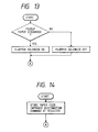
- the specific command signal is a paper refeed command signal
- the recording medium in spare paper feeding is automatically discharged, and a sheet is fed again from a paper feed entrance which is newly designated. Even if the recording sheet is fed by the spare paper feed signal, a change in paper feed entrance can be facilitated.
- the specific command signal is a paper discharge port designation command or a resolution switching command, the change in paper discharge port or resolution can be facilitated even if the recording medium in spare paper feeding is already present as described above.
- the specific command signal is a paper feed entrance designation command for the spare paper feed signal and the paper feed entrance designation command is changed during spare paper feed control, the recording medium fed by the spare paper feed signal is invalidated.
- the paper feed entrance designation command is validated for the recording medium which will be fed by the next spare paper feed signal, thereby facilitating control.
- a means for measuring a pile-limit time or a spare paper feed stop time in the feed path of the paper sheet in spare paper feeding When the pile-limit time or the like exceeds one of the plurality of predetermined times, the piled paper is temporarily discharged outside the laser printer. Piling of the paper sheet for a long period of time in spare paper feeding can be prevented, and reliability of image quality can be improved.
- a time for adversely affecting the paper sheet varies depending on the atmosphere in which the paper sheet is placed. An appropriate time can be selected and set according to the present invention.
- an abnormal event treatment for an abnormal event occurring during spare paper feeding by a spare paper feed request which is different from a treatment of an abnormal event during printing, performed by a normal print request is performed to improve printing quality of the image forming apparatus while all the conventional problems are solved.
- Fig. 8 is a view showing a schematic arrangement of a laser beam printer according to the first embodiment.
- the same reference numerals as in the conventional techniques (Figs. 1, 2 and 4 to 6) denote the same parts in Fig. 8, and a detailed description thereof will be omitted.
- the first embodiment has a plurality (three) of paper feed entrances, and cassettes 910, 920, and 930 can be mounted in correspondence with the respective paper feed entrances.
- the cassette 930 is an optional cassette for storing recording media such as envelopes and postal cards.
- An envelope or postal card is fed by a paper feed roller 93.
- Recording media having desired sizes are stored in the upper and lower cassettes 910 and 920 and are fed by paper feed rollers 91 and 92, respectively.
- a desired one of the three types of recording media can be selected and is subjected to image recording.
- face-up or face-down paper discharge can be selected.
- a flapper 53 is arranged to switch a feed path so as to select a desired paper discharge method.
- Fig. 9 is a flow chart for explaining an operation of the image forming apparatus (laser beam printer) shown in Fig. 8.
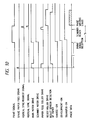
- Figs. 10 and 11 are timing charts showing the operation of this image forming apparatus.
- a spare paper feed signal is provided in addition to a print signal.
- the flow advances from step S1 to step S2.
- step S3 to step S4 to feed a recording medium to a preset predetermined position (steps S4 to S8).
- control is performed to validate a predetermined command signal immediately before a recording request signal (print signal) becomes true or enabled (steps S12 and S16).
- processing corresponding to this command signal is performed (step S17).
- a time T in Figs. 10 and 11 is a period for which the predetermined command signal is enabled or validated.
- a timing chart for enabling a scanner motor drive signal upon reception of a print signal is shown in Fig. 10.
- a timing chart for enabling a scanner motor drive signal upon reception of a spare paper feed signal is shown in Fig. 11.
- a time between reception of the print signal and start of image write operation satisfies condition T1 (Fig. 11) ⁇ T0 (Fig. 10).
- the laser beam printer is arranged to be operated at timings shown in Fig. 11.
- the time T has a value determined by a feed time required to feed a recording medium to the predetermined position, a pre-rotation time of the photosensitive body, and the like.
- a paper refeed command is defined as follows.
- One of the three paper feed entrances i.e., the paper feed entrance of the optional feeder (i.e., the feeder for envelopes or postal cards), the upper paper feed entrance, and the lower paper feed entrance is designated.
- the paper feed entrance of the optional feeder i.e., the feeder for envelopes or postal cards
- the upper paper feed entrance i.e., the feeder for envelopes or postal cards
- the lower paper feed entrance is designated.
- auto-discharge is performed for the recording medium already fed in response to the spare paper feed signal, and at the same time, the medium is fed from the designated paper feed entrance.
- the auto-discharge is an operation for discharging a recording medium fed in response to a spare paper feed signal to a predetermined discharge port without performing a recording operation. This operation is also performed when jamming processing is released and initial resetting upon power-ON operation is performed in steps S14 and S34.
- step S3 determination in step S3 is made such that a spare paper feed signal has been received. Note that data for designating the paper feed entrance is received together with the paper refeed command.
- the above operation is an example, and the following operation may be performed in accordance with another arrangement of the controller. That is, if the paper sizes of the upper and lower cassettes 910 and 920 are equal to each other and when a no-paper state occurs or a no-cassette paper feed entrance is selected, a recording medium can be automatically fed from the other cassette.
- Control may be performed to neglect designation of the paper feed entrance of the optional feeder 930 if the optional feeder 930 is not set.
- a flapper solenoid (not shown) is turned on to move the flapper 53 in a direction indicated by an arrow a .
- the face-up and face-down discharge methods are exemplified. However, this can be true for a plurality of discharge trays.
- the discharge trays are respectively assigned to the host units.
- data processing from the first and second host units can be simultaneously performed by a controller inside the printer. If image development in the second host unit is completed prior to that in the first host unit while a recording medium is fed in spare paper feeding so as to print information on the basis of the data from the first host unit, the discharge port designation command may be transmitted from the controller.
- the paper discharge for the second host unit is designated, the print data of the second host is recorded on the recording medium, and this recording medium is discharged onto the discharge tray corresponding to the second host unit. After printing on the basis of the data from the second host unit is started, a print request from the first host is received at a printable timing, and a predetermined print operation is performed.
- the recording media can be selectively used by the different host units.
- a command signal can be flexibly input, thereby improving user convenience.
- a specific command is a paper feed entrance designation command for a spare paper feed signal.
- this command is not effected for the recording medium.
- Image recording of the recording medium is performed on the basis of reception of an image recording request signal.
- the paper feed entrance designation command received during spare paper feed control of the recording medium of the previous page becomes validated for a spare paper feed signal input upon the start of image recording.
- the paper feed entrance designation command is temporarily stored in a paper feed entrance designation command register.
- step S2 in Fig. 9 when a print signal as an image recording request signal is received, the temporarily stored paper feed entrance designation command is transferred to a paper feed entrance designation register which is read-accessed to actually feed a recording medium.
- This register is a paper feed entrance designation register read-accessed at the start of operation in steps S7, S20, and S24 of the flow chart in Fig. 9.
- the recording medium waiting within the laser printer in spare paper feed control is discharged, and recording is performed on a recording medium fed from any paper feed entrance, thereby providing a new function, improving performance, and simplifying the recording operation.
- paper refeed processing of this embodiment is effective when a recording medium is left in the apparatus for a long period of time, when the current recording medium is changed to a new one or a printer is shared, or when the current processing is temporarily interrupted in response to a paper refeed command during prefeed waiting (because a print operation cannot be immediately started due to a time required for image development or the like) and processing of a new host unit is preferentially performed.
- the discharge port designation command for designating a discharge port allows to add a new function and improve performance.
- the printer since a change in discharge port corresponding to a host computer can be easily performed, when processing for the first host unit is prolonged, the data from the second host unit is printed on the recording sheet in spare paper feeding and this paper sheet is discharged to a specific discharge port. Thereafter, the discharge port for the first host is set again, and a recording paper is fed in spare paper feeding.
- the specific command is a paper feed entrance designation command for the spare paper feed signal
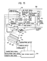
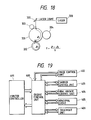
- Fig. 15 is a view showing a basic arrangement of a recording unit of an electrophotographic laser beam printer (to be referred to as an LBP hereinafter) using laser light as an exposing means.
- an LBP electrophotographic laser beam printer
- the LBP comprises a controller unit 200, a high voltage source 250, a laser unit 300, a collimator lens 311, a cylindrical lens 312, a polygonal mirror 313 consisting of a hexahedral mirror, a scanner motor 314 for rotating the polygonal mirror 313, a focusing lens 314, a BD mirror 320, a photosensitive drum 331, a transfer roller 332, a charge roller 333, a development cylinder 334, and a reflecting mirror 335.
- the controller unit 200 includes a main control unit 201, a scanner clock frequency-divider 202 for controlling a rotation number of the scanner motor 314 in response to a resolution selection signal, a BD counter 203, an oscillator 204, a laser driver & amplifier 205 for amplifying an APC control signal and a video signal to emit a laser beam, an amplifier 206 for amplifying a PD signal upon laser emission, and a wave shaping circuit 207 for forming a waveform of the BD signal.
- FIG. 16 A detailed relationship between the controller unit 200 and the scanner unit in Fig. 15 is shown in Fig. 16.
- the same reference numerals as in Fig. 15 denote the same parts in Fig. 16, and a detailed description thereof will be omitted.
- a scanner unit 350 has a scanner driver & control unit 351.
- a scanner clock frequency-divider 202 in the controller unit 200 frequency-divides a reference signal from the oscillator 204 of, e.g., a quartz oscillator in accordance with a frequency-division ratio select signal to generate a scanner clock signal.
- the scanner clock signal is output to the scanner unit 350.
- the frequency-division ratio select signal is a 2-bit signal which can output a maximum of four rotation number switching signals. The number of rotation numbers is not limited to four. If a frequency-division ratio select signal has three or more bits, any rotation number can be selected, and recording outputs at many resolutions can be obtained, as a matter of course.
- the scanner motor 314 is rotated by the rotation number corresponding to the scanner clock signal from the scanner clock frequency-divider 202.
- the scanner clock signal is compared with a tack signal generated upon rotation of the scanner motor 314 as a reference signal of a phased locked loop (PLL).
- PLL phased locked loop
- Rotation of the scanner motor 314 is controlled so that the scanner clock signal coincides with the tack signal.
- constant speed rotation control of the scanner motor 314 can be performed so as to correspond to a desired resolution.
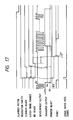
- Control of the operation of this embodiment having the above arrangement will be described below. Control timings of the embodiment is shown in a timing chart of Fig. 17.
- the LBP of this embodiment is arranged to variably control the rotation speed of the scanner motor 314 in accordance with a desired resolution, so that a resolution (recording density) can be arbitrarily set. For example, switching between resolutions of 240 dpi and 300 dpi and of 300 dpi and 400 dip, and the like can be performed by the single laser beam printer.
- the main control unit 201 When a new resolution is input from an external control unit (not shown) or an operation panel during rotation of the scanner motor 314, the main control unit 201 outputs a corresponding resolution switching signal to the scanner clock frequency-divider 202 in accordance with a set input.
- the scanner clock frequency-divider 202 changes a scanner clock signal, thereby changing the rotation number of the scanner motor 314.
- a scanner ready signal representing constant speed rotation of the scanner motor 314 is set to be false (not-ready).
- a laser output is inhibited, a BD signal is not detected because the rotation number of the scanner motor 314 is being changed.
- a BD not-ready state is set, and the LBP apparatus of this embodiment becomes a not-ready state as a whole.
- a printer ready signal becomes false.
- an input video signal from an external control unit or the like is masked by an AND gate (not shown) in the BD counter 203, thereby generating a laser diode enable signal.
- a development/transfer output is set in an OFF state.
- the development/transfer system of this embodiment employs an image formation process by roller charge/transfer, especially, a voltage of several hundreds of negative volts to about -1 kV (-1 kV in this embodiment) is applied to the transfer roller, so that the toner attracted to the transfer roller can be transferred to the drum even if the development/transfer output is set in the OFF state.
- the scanner driver & control unit 351 changes the rotation number of the scanner motor 314 in accordance with the scanner clock signal and performs rotation control so as to obtain a predetermined rotation number specified by the resolution switching signal (i.e., the frequency-division ratio select signal).
- the scanner ready signal becomes "1" (ready).
- the main control unit 201 Upon reception of the scanner ready signal of "1", the main control unit 201 disables at least the development output (or the main control unit 201 confirms that the development output is OFF), and the following control is performed for the transfer output.
- a predetermined positive bias voltage having a magnitude smaller than that of the normal transfer output is applied. This is a very effective means for erasing a trace of a recording medium.
- An impedance between the photosensitive drum 331 and the transfer roller 332 in the presence of the recording medium is set to be equal to that in the absence of the recording medium.
- This bias voltage V t0 is determined by an LBP arrangement. In this embodiment, the bias voltage V t0 is set to be about 2 kV, which is half of the normal transfer output.
- the voltage value is not limited to this voltage value, and varies depending on the ambient conditions, and especially humidity and properties of the recording medium. An optimal value is preferably set using these values as parameters.
- the bias voltage can be automatically adjusted to a desired transfer voltage value on the basis of humidity information. Special paper by manual feeding can be used as a recording medium. In this case, automatic adjustment can be similarly performed by sending recording medium information through an operation panel or a host computer.
- a laser diode enable output is set to be active.
- the amplifier 205 is biased to obtain a BD signal serving as a horizontal sync signal to turn on a laser.
- laser light is guided from the BD mirror 320 to a BD detector through an optical fiber and is sent to the BD counter 203 by forming a waveform by the wave shaping circuit 207, thereby detecting the BD signal.
- Upon detection of the BD signal in order to determine a BD period, exposure is performed until the periods are counted by at least two lines (two main scanning cycles). As a result, laser light is emitted on an image area of the photosensitive drum 331.
- the development output is OFF, and a latent image is not formed on the photosensitive drum 331.
- a sequence for clearing the transfer output is executed, and a toner tends not to be transferred to the transfer roller.
- a clean state can always be maintained.
- a time t in Fig. 17 is a sum of a time interval between time when a laser beam is radiated on the photosensitive drum 331 and time when a BC sync signal is enabled, and a time interval between time when a latent image formed within the enable time of the BD sync signal passes through a transfer contact point with the transfer roller 332 and time when the transfer roller 332 is rotated at least one revolution.
- the printer ready signal is set at "1", thereby obtaining a printer ready state.
- a normal print sequence is started again in response to an external print signal.
- a time interval t11 is a very short time interval. When a controller image development is prolonged, this time is prolonged accordingly. That is, the time t11 varies depending on the image development time.
- the recording medium fed in the spare paper feed signal receives a resolution switching signal during feeding, and when the recording medium reaches the predetermined position upon a lapse of the time t after setting of the BD ready state, the same operation as in the stop state can be performed.
- processing for an abnormal event generated until an end of vertical synchronization of a recording sheet in spare paper feeding is performed by processing different from an abnormal event treatment executed upon reception of a normal print request.
- a cassette during spare paper feeding is removed, and the sheet is discharged, thereby performing appropriate processing for an abnormal event such as discharge of a sheet or a scanner failure in accordance with a printer state.
- FIG. 19 An arrangement of the image forming apparatus of this embodiment is the same as that of the conventional example (Fig. 1), and a detailed description thereof will be omitted.
- a control system of the image forming apparatus of this embodiment is shown in Fig. 19.
- An engine control unit 400 performs exchange of a command/status signal with a printer controller 401, exchange of a vertical sync request/vertical sync signal, reception of image data, and output of a horizontal sync signal. At the same time, the engine control unit 400 performs control of the respective parts of the engine.
- An image control unit 402 executes driving/stopping of a semiconductor laser and a polygonal scanner on the basis of an instruction from the engine control unit 400.
- a carrier control unit 403 feeds a sheet and drives/stops the resist roller for vertical synchronization. When the engine control unit 400 receives a spare paper feed request, the carrier control unit 403 also performs spare paper feed control on the basis of an instruction from the engine control unit 400.
- the high voltage control unit 404 outputs high charge, development and transfer voltages having predetermined values at timings instructed by the engine control unit 400.
- the abnormal event treatment unit 405 performs a treatment for an abnormal event occurring during a standby state or during printing upon reception of the print request.
- An abnormal event treatment unit 406 feeds a sheet to a predetermined position and stops it upon reception of a spare paper feed request, and performs an abnormal event treatment for an abnormal event occurring until reception of a vertical sync signal upon reception of a print request.
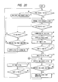
- the abnormal event treatment unit 406 performs processing different from that of the abnormal event treatment unit 405. Actual control will be described with reference to flow charts of Figs. 20 and 21.
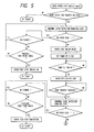
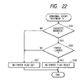
- Fig. 20 is the flow chart of an operation performed upon reception of a normal print request. It is determined whether a print request is received (step S1). If NO in step S1, reception of a spare paper feed request in Fig. 21 is checked (step S2). If YES in step S1, the abnormal event treatment unit 405 performs a control task A (step S3). As shown in Fig. 22, in the abnormal event treatment task A, the mounting/non-mounting of the cassette is checked (step S35), and the presence/absence of the sheet is checked (step S36). When a paper cassette is not mounted in the printer or a sheet is not present in the paper cassette, a no-paper flag is set (step S37).
- step S38 When the cassette is mounted and sheets are present, the no-paper flag is reset (step S38).
- the flow advances from step S4 to step S5 in Fig. 20.
- step S6 When first printing is not performed, the print end state of the previous page is checked (step S6). Otherwise, paper feeding is stopped (step S7).
- the abnormal event treatment task A is started again if first printing is being performed. If the printing of the previous page is not completed in step S6, the abnormal event treatment task A is started again.
- step S4 If the no-paper flag is reset in step S4, the scanner is started and the voltage is raised to a high voltage to start paper feeding (steps S8 and S9).
- a predetermined period of time T1 (sec) has elapsed after paper feeding is started (steps S10 and S11)
- the paper feed roller is stopped, and a vertical sync request is output to the controller (step S13).
- the start of image data output is instructed (step S15), and a paper feed timing of the next page is set by a timer T2 (sec).
- T2 has elapsed, the next print request check is started (steps S16 and S17).
- the abnormal event treatment task B is started (step S22).
- the no-paper flag is set or reset (steps S46 and S47) in accordance with mounting/non-mounting of the cassette and the presence/absence of the paper sheet (steps S44 and S45).
- the flow advances from step S23 to step S24 of Fig. 21. If a standby state is detected, the abnormal event treatment task B is executed again. Otherwise, paper feeding is stopped or the abnormal event treatment task B is performed again in accordance with the print end state of the previous page (step S25).
- step S23 When the no-paper flag is not set in step S23, the paper feed roller is driven (step S27). When a time T3 (sec) required for feeding the paper sheet to the predetermined position has elapsed (steps S28 and S29), the paper feed roller is stopped (step S30). The spare paper feed end flag is set (step S31), and the abnormal event treatment task B is started. In this abnormal event treatment task B, the flow advances from step S41 to step S42 of Fig. 23. Mounting/non-mounting of the cassette is checked. If a no-cassette state is determined, jamming processing is performed (step S43). Otherwise, normal processing is restored. Reception of a print request is awaited, and the abnormal event treatment task B is kept started. Upon reception of a print request, the spare paper feed end flag is reset (step S34), and the flow returns to step S13 of Fig. 20 through a connector A.
- the abnormal event treatment task A shown in Fig. 22 is performed.
- the abnormal event treatment task B shown in Fig. 23 is performed. Therefore, an appropriate abnormal event treatment can be performed in accordance with the current operation mode.
- the sheet stopped at the resist roller position in spare paper feeding is often subjected to a positional error, removal of the sheet, and tearing of the trailing end of the sheet.
- problems such as contamination of a lower surface of a sheet due to a positional error of the sheet can be solved.
- Figs. 24 to 28 are views showing the fourth embodiment of the present invention.
- Fig. 24 shows an arrangement of an apparatus according to the fourth embodiment.
- This apparatus includes a photosensitive drum 500, a semiconductor laser 501, a polygonal mirror scanner 502, a charge roller 503, a developing unit 504, a transfer roller 505, a cleaner 506, a fixer 507, a first paper feed roller 508, a second paper feed roller 509, a paper feed tray 510, a paper cassette 511, a resist roller 512, and paper sensors 513 and 514.
- the arrangement of this embodiment is different from that of the third embodiment in that a sheet can be fed from the paper feed tray, and that the paper sensor 513 is added in front of the resist roller 512. With this arrangement, processing performed upon discharge of a sheet in spare paper feeding by a user before a print request is received is shown in this embodiment.
- a control system of this embodiment is the same as that of the third embodiment in Fig. 19.
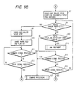
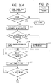
- step E1 When a print request is received in step E1, data of a paper feed entrance of the first or second paper feed roller 508 or 509 which is designated by the controller is read (step E2).
- An abnormal event treatment task A is executed (step E3) (to be described later in detail), and the paper feed roller of the designated paper feed entrance is driven (steps E5 and E6). Thereafter, control waits until the paper sensor 513 detects the presence of the sheet (step E7).
- step E9 Upon detection of the presence of the sheet, when a predetermined period of time T4 has elapsed (steps E8 and E9), the paper feed roller is stopped (step E10), and a vertical sync request is output to the controller (step E11).
- step E12 When the controller receives the vertical sync signal, the flow advances from step E12 to step E13 to drive the resist roller 512, and writing of an image on the photosensitive drum 500 is started.
- step E14 and E15 When a predetermined period of time T5 has elapsed (steps E14 and E15), writing of the image is completed, and the flow returns to the "start".
- the abnormal event treatment task A in step E3 is substantially the same as that of the first embodiment except that mounting/non-mounting of the designated cassette in each decision step is determined and that the presence/absence of a sheet in the designated cassette is determined.
- step E21 When a spare paper feed request is received prior to a print request, the flow advances from step E21 to step E22 in Fig. 26, and the designated paper feed roller is driven (steps E22 to E25). Thereafter, control waits until the paper sensor 513 detects the presence of a sheet (step E26). Upon detection of the presence of the sheet, when the predetermined period of time T4 has elapsed (steps E27 and E28), the paper feed roller is stopped (step E29). The controller waits for a print request (steps E30). Upon reception of a print request, the abnormal event treatment task B is performed (step E31). When a normal state is detected, a vertical sync request is output to the controller (step E33).
- step E34 Upon reception of the vertical sync signal (step E34), the resist roller 512 is driven and image write access of the photosensitive drum 500 is started (step E35).
- step E35 When the predetermined period of time T5 has elapsed (steps E36 and E37), the image write access is completed, and the flow returns to the "start".
- the sheet is fed to the resist roller position, and the controller waits for a print request while the paper feed roller is kept stopped.
- the abnormal event treatment task B shown in Fig. 28 is started.
- the abnormal event treatment task B if the "presence" of the sheet is detected by the resist sensor (step E41), a spare paper feed reset flag is reset (step E42). However, if a no-paper state is detected, the spare paper feed reset flag is set (step E43). When spare paper feeding is completed and a print request is received, the content of the spare paper feed reset flag is read.
- step E32 the controller determines that the sheet in the spare paper feeding is discharged (step E32). The flow returns to step E2 through connectors A of Figs. 26 and 25 to cause the paper feed roller to feed a sheet. However, if the above flag is set at "0", the flow advances to step E33, and vertical synchronization is performed to start an image output.
- an appropriate abnormal event treatment can be performed in accordance with an operation mode.
- a sheet in spare paper feeding is stopped at the position of the sensor 513 and is discharged, a sheet can be fed again from the paper feed tray. Otherwise, a normal operation can be performed.
- Fig. 29 shows arrangement of an apparatus of the fifth embodiment of the present invention.
- This apparatus has a two-stage paper feed cassette, and paper paths from the respective paper feed entrances to a resist roller do not interfere with each other.
- the apparatus comprises a paper feed roller 609, a cassette 610, a paper feed roller 609a, and a cassette 610a.
- Processing of the apparatus having the above arrangement in each operation mode is substantially the same as the processing of the fourth embodiment shown in Figs 20 and 21.
- An abnormal event treatment task A of this embodiment is substantially the same as that of the fifth embodiment shown in Fig. 22.
- An abnormal event treatment task B of this embodiment is substantially the same as that of the third embodiment except that mounting/non-mounting of the designated cassette and the presence/absence of a sheet are determined in each decision step, as shown in Fig. 30.
- a spare paper feed request is received, and a sheet in spare paper feeding is fed from the designated paper feed entrance.
- a cassette at the paper feed entrance subjected to spare paper feeding is removed while the fed sheet is kept stopped at the resist roller position, jamming processing is performed.
- a cassette is removed from a paper feed entrance different from that in spare paper feeding no jamming processing is performed. This can prevent an unnecessary jamming event.
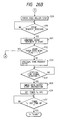
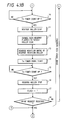
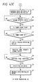
- Fig. 32 is a flow chart showing an operation of spare paper feeding according to the sixth embodiment of the present invention.
- an operation performed upon reception of a print request prior to reception of a spare paper feed request is the same as that of the third embodiment (Fig. 20).
- Abnormal event treatment tasks A and B are the same as those of the third embodiment (Figs. 22 and 23).
- An operation for receiving a spare paper feed request prior to reception of a print request will be exemplified below.
- the stopped scanner motor when a print request is received during a standby state of the printer, the stopped scanner motor is driven.
- paper feeding is started.
- a sheet is fed to the resist roller position while the scanner motor is kept stopped (steps Q3 to Q6).
- Driving of the scanner motor is started (step Q8) upon reception of a print request (step Q7), and the abnormal event treatment task B is started (step Q9).
- a vertical sync request is output (step Q13).
- image write access is started (step Q15).
- step Q10 when the rotation number of the scanner motor does not reach the predetermined rotation number within a predetermined period of time at the end of spare paper feeding even if the scanner motor is driven upon reception of the print request, the flow advances from step Q10 to step Q11 to determine that a failure flag is set.
- the sheet in spare paper feeding is forcibly discharged regardless of an instruction from the controller (step Q12). Therefore, piling of an unnecessary sheet within the printer can be prevented.
- Figs. 33 to 35 show the seventh embodiment of the present invention.
- the mechanical structure of this embodiment is the same as that shown in Fig. 1, and a detailed description thereof will be omitted.
- a timer 625 is added to the arrangement of Fig. 1 in a control system of the seventh embodiment shown in Fig. 33.
- the timer 625 counts a time from the stop of a sheet after a spare paper feed request is supplied from a printer controller 621 to an engine control unit 620, and the sheet is fed to a predetermined position and is stopped and waits for receiving a print request.
- a temperature sensor 627 comprises, e.g., a thermistor.
- a ROM 628 stores pile-limit time corresponding to each temperature.
- the engine control unit 620 outputs to the timer 625 a pile-limit time as a time T3 corresponding to a temperature detected by the temperature sensor 627, thereby setting the time T3.
- FIG. 34 A flow chart of the engine control unit 620 according to this embodiment is shown in Fig. 34.
- the engine control unit 620 sets the time T3 (step E0).
- step E1 The presence/absence of a print request from the printer controller 621 is checked (step E1).
- step E2 the presence/absence of a spare paper feed request is checked (step E2). If YES in step E2, the spare paper feed flag is set (step E3). However, when the spare paper feed request is not present, the presence/absence of the print request is checked again. If the presence of the print request is detected, the paper feed roller is driven without setting the spare paper feed flag (step E4).
- step E5 When the sheet reaches the resist paper sensor 51 (Fig. 1) (step E5), the sheet abuts against the resist roller 50 (Fig. 1).
- step E6 and E7 When a predetermined period of time T1 (sec) for forming a predetermined loop has elapsed (steps E6 and E7), i.e., when feeding of the sheet to the resist roller position upon reception of the print request or spare paper feed request, the paper feed roller is stopped (step E8), and the spare paper feed flag is checked (step E9). If the spare paper feed flag is OFF, a vertical sync request is output as in the conventional case (step E19).
- a pile-limit timer T3 for monitoring a pile time of the sheet in spare paper feeding is set (step E10), and the controller waits for a print request (step E11). It is then checked whether the time of the pile-limit timer T3 has elapsed while reception of a print request is being checked (step E12). When a print request is received prior to the lapse of the time of the pile-limit timer T3, the pile-limit timer is reset (step E15), and the spare paper feed flag is turned off (step E16). When the time T2 (sec) has elapsed (steps E17 and E18), a vertical sync request is output (step E19).
- step E20 and E21 The subsequent operations are the same as those of the conventional technique (steps E20 and E21).
- the spare paper feed flag is set to OFF (step E13).
- the piled sheet is discharged outside the laser beam printer (step E14), and the flow returns to the "start".
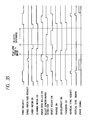
- Timing chart of Fig. 35 This timing chart exemplifies a series of operations as follows.
- the first page is printed in response to a normal print request.
- the next page is fed in spare paper feeding in response to a spare paper feed request, and no print request is received after a lapse of the time T3 (sec).
- An auto-discharge mode is set, and the sheet is automatically discharged.
- a sheet is fed from a paper feed cassette again upon reception of a print request.
- the sheet in spare paper feeding can be discharged only when an appropriate period of time has elapsed.
- a humidity sensor may be arranged in place of the temperature sensor.
- sheets tend to be curled when the humidity is increased.
- the appropriate time of the pile-limit timer T3 can be set in accordance with a humidity detected by the humidity sensor.
- both a temperature sensor and a humidity sensor are arranged to appropriately set the time of the pile-limit timer T3 on the basis of the temperature and humidity values detected by these sensors.
- a plurality of time values need not be stored in the ROM.
- a desired time may be input from a key input means and may be stored in a RAM.
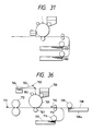
- Figs. 36 and 37 are views showing the eighth embodiment of the present invention.
- Fig. 36 shows an arrangement of an apparatus according to the eighth embodiment.
- This apparatus has a second paper feed roller 714 and a paper feed cassette 715.
- a roller 711 is not a roller for correcting ramp upon abutment with the leading end of the sheet, but serves as a ramp feed roller for correcting ramp by bringing one side of the sheet into contact with one side surface of the feed path.
- a loop need not be formed at the resist roller portion.
- the sheet tends to be curled if it is piled for a long period of time within the apparatus. Curling adversely affects the subsequent feed operation.
- a sheet pile-limit time is changed for each paper feed entrance to perform optimal control.
- step P1 The presence/absence of a print request from a printer controller is checked in step P1. If no print request is received, the presence/absence of a spare paper feed request is checked (step P2). If NO in step P2, the flow returns to step P1 to check the presence/absence of a print request.
- a spare paper feed flag is set (step P3), and the flow advances to step P4.
- step P4 When the print request is received in step P1, a paper feed roller 709 and the feed roller 711 are driven (step P4).
- step P5 When the resist sensor 710 detects the sheet (step P5), the paper feed roller 709 and the roller 711 are stopped (step P6). It is checked in step P7 whether the spare paper flag is set. If NO in step P7, the flow advances to step P20 to output a vertical sync request. However, if YES in step P7, data associated with designation of a paper feed entrance is read out from a RAM (not shown) to determine whether the designated paper feed entrance is a paper feed entrance of a first cassette 708a or a paper feed entrance of the second cassette 715 (step P8).
- a time T L1 is set as the time of the pile-limit timer T3 (step P11).
- a time T L2 s set (step P10).
- step P12 and P13 it is checked whether counting of the pile-limit timer T3 is completed while the presence/absence of a print request is being checked.
- the spare paper feed flag is set to OFF (step P14), and the piled sheet is discharged outside the apparatus (step P15), and the flow returns to the "start”.
- step P16 the spare paper feed flag is set to OFF (step P17).
- the time T2 (sec) is waited, and the vertical sync request is output (steps P19 and P20).
- step P21 image data output is started (step P22), and this sequence control is ended.
- the designated paper feed entrance is read, and the paper feed roller of the designated paper feed entrance is driven.
- the paper sheet reaches the resist sensor 710 and is stopped while waiting for a print request, it is determined which paper feed entrance is designated, and a value corresponding to the designated paper feed entrance is set in the pile-limit timer.
- the paper path of the first cassette is straight, and the resist loop need not be formed, so that a limit time can be long.
- the limit time is set to be shorter than that of the first cassette. That is, condition T L1 > T L2 is satisfied. A time which adversely affects the sheet is changed.
- the time of the pile-limit timer T3 is determined in accordance with the designated paper feed entrance, image formation with an appropriate pile-limit time can be performed even if either paper feed entrance is used.
- the time elapsed after the spare paper feeding is performed is counted as a pile-limit time.
- a time counted upon reception of a spare paper request or upon the start of driving of the paper feed roller may be counted.
- This embodiment exemplifies a laser printer.
- the present invention is also applicable to a liquid crystal printer or an LED printer.
- This embodiment has a plurality of paper feed means, and the current paper feed means can be changed without automatically discharging a sheet of spare paper feeding after spare paper feeding is performed.
- Fig. 38 shows a state wherein spare paper feeding is performed for the first to third paper feed means 31 to 33 in the printer of Fig. 7, and recording sheets S1 to S3 wait at spare paper feed positions C1 to C3, respectively.
- the first paper feed means 31 to 33 are controlled by spare paper feeding by a controller (i.e., a control circuit such as a microcomputer) serving as a paper feed control means on the basis of spare paper feed signals before a printer operation start signal (print start signal), so that the recording sheets S1 to S3 are fed as sheets in spare paper feeding. Feeding of the recording sheets S1 to S3 is stopped when leading ends of the recording sheets S1 to S3 are located at predetermined spare paper feed positions C1 to C3 in front of a merge point A of the respective sheet paths P1 to P3 of the paper feed means 31 to 33, respectively. Spare paper feeding is completed, and the recording sheets are set in the waiting state.
- a controller i.e., a control circuit such as a microcomputer
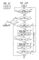
- Fig. 41 is a flow chart showing a paper feed sequence including a spare paper feed sequence.
- the paper feed sequences of the paper feed means 31 to 33 are identical to each other, and only a paper feed sequence of the third paper feed means 33 serving as a manual feed means will be described below.
- Fig. 42 shows a schematic arrangement of a printer having a two-side print function.
- Paper feed means comprise a cassette paper feed means 31, a manual paper feed means 33, and a paper refeed means.
- the paper feed sequences of the paper feed means 31 and 33 are the same as those of the paper feed means 31 and 33 of the ninth embodiment.
- a paper sheet is fed from the paper feed means 31 or 33 to a transfer portion B.
- An image is transferred to the first surface of the fed recording sheet.
- the recording sheet to which the image is fixed by a fixer 12 is discharged on a paper discharge tray 20 from a discharge roller 19 through an upper guide surface of a paper discharge flapper 13 located at the first selection posture, i.e., a horizontal posture in a one-side print mode.
- the recording sheet on which an image is formed on the first surface thereof passes through the fixer 12 and enters into a feedback sheet path P5 under the lower guide surface of the paper discharge flapper 13 switched to a second selection posture, i.e., an obliquely upward posture.
- the recording sheet is then guided to a switch-back path 15 by carrier rollers 14 (i.e., the surface having the image faces down).
- the recording sheet is then switched back to a paper refeed sheet path P6 by cooperation of a recording sheet sensor 18, a reverse rotation roller 16, a reverse rotation flapper 17.
- the paper refeed path P6 merges into the separate sheet paths P1 and P3 of the cassette paper feed means 31 and 33 and communicates with the common sheet path P4 connected to the transfer portion B.
- the recording sheet whose image on the first surface faces down is guided from the paper refeed path P6 to the common sheet path P4.
- the recording sheet is fed by the resist roller 9 again to the transfer portion B at a predetermined timing.
- An image is transferred to the second surface of the recording sheet.
- the sheet is then guided to the fixer 12, and the image on the second surface is fixed.
- the sheet is then guided to the paper discharge roller 19 through the paper discharge flapper 13 switched to the first posture. Therefore, the recording sheet having images respectively on both sides is output on the paper discharge tray 20.
- Fig. 43 is a flow chart of a paper refeed sequence including a spare paper feed sequence in the two-side print mode.
- an image forming apparatus which has an image signal generator for generating an image signal, an image forming unit for forming an image on a recording medium based on the generated image signal, a feeding unit for feeding the medium to the image forming unit, and a controller for outputting different commands to the image forming unit to control the image forming unit
- the feeding unit performs spare paper feeding of the medium to a predetermined position before the generator is set in an image signal output enable state and feeds the medium from the predetermined position to the image forming unit after the generator is set in the image signal output enable state
- the image forming unit validates a specific command of the different commands when the specific command is received during at least a spare paper feed period from start of spare paper feeding of the recording medium to start of paper feeding from the predetermined position, thereby maximizing the function of the image forming apparatus.
Landscapes
- Engineering & Computer Science (AREA)
- Physics & Mathematics (AREA)
- General Engineering & Computer Science (AREA)
- General Physics & Mathematics (AREA)
- Theoretical Computer Science (AREA)
- Optics & Photonics (AREA)
- Control Or Security For Electrophotography (AREA)
- Sheets, Magazines, And Separation Thereof (AREA)
- Handling Of Cut Paper (AREA)
- Accessory Devices And Overall Control Thereof (AREA)
Priority Applications (1)
| Application Number | Priority Date | Filing Date | Title |
|---|---|---|---|
| EP96110232A EP0740267B1 (de) | 1990-02-17 | 1991-02-18 | Bilderzeugungsgerät |
Applications Claiming Priority (8)
| Application Number | Priority Date | Filing Date | Title |
|---|---|---|---|
| JP2037062A JPH03243547A (ja) | 1990-02-17 | 1990-02-17 | シート材給送装置 |
| JP37062/90 | 1990-02-17 | ||
| JP2135583A JP2791186B2 (ja) | 1990-05-25 | 1990-05-25 | 画像形成装置 |
| JP135583/90 | 1990-05-25 | ||
| JP143730/90 | 1990-05-31 | ||
| JP2143730A JPH0436765A (ja) | 1990-05-31 | 1990-05-31 | 画像形成装置 |
| JP167646/90 | 1990-06-25 | ||
| JP2167646A JPH0462078A (ja) | 1990-06-25 | 1990-06-25 | 画像形成装置 |
Related Child Applications (2)
| Application Number | Title | Priority Date | Filing Date |
|---|---|---|---|
| EP96110232A Division EP0740267B1 (de) | 1990-02-17 | 1991-02-18 | Bilderzeugungsgerät |
| EP96110232.4 Division-Into | 1996-06-25 |
Publications (3)
| Publication Number | Publication Date |
|---|---|
| EP0443494A2 true EP0443494A2 (de) | 1991-08-28 |
| EP0443494A3 EP0443494A3 (en) | 1993-04-07 |
| EP0443494B1 EP0443494B1 (de) | 1997-07-09 |
Family
ID=27460360
Family Applications (2)
| Application Number | Title | Priority Date | Filing Date |
|---|---|---|---|
| EP96110232A Expired - Lifetime EP0740267B1 (de) | 1990-02-17 | 1991-02-18 | Bilderzeugungsgerät |
| EP91102279A Expired - Lifetime EP0443494B1 (de) | 1990-02-17 | 1991-02-18 | Druckvorrichtung |
Family Applications Before (1)
| Application Number | Title | Priority Date | Filing Date |
|---|---|---|---|
| EP96110232A Expired - Lifetime EP0740267B1 (de) | 1990-02-17 | 1991-02-18 | Bilderzeugungsgerät |
Country Status (3)
| Country | Link |
|---|---|
| US (1) | US5258779A (de) |
| EP (2) | EP0740267B1 (de) |
| DE (2) | DE69126717T2 (de) |
Cited By (1)
| Publication number | Priority date | Publication date | Assignee | Title |
|---|---|---|---|---|
| EP0735740A3 (de) * | 1995-03-31 | 1997-10-01 | Canon Kk | Gerät und Verfahren zur Bildverarbeitung und zur Bilderzeugung |
Families Citing this family (17)
| Publication number | Priority date | Publication date | Assignee | Title |
|---|---|---|---|---|
| EP0416832B1 (de) * | 1989-09-07 | 1996-07-10 | Canon Kabushiki Kaisha | Bilddarstellungsgerät |
| EP0482641B1 (de) * | 1990-10-26 | 1998-05-27 | Canon Kabushiki Kaisha | Bilderzeugungsvorrichtung |
| JPH0789162A (ja) * | 1993-05-24 | 1995-04-04 | Samsung Electronics Co Ltd | プリント装置の用紙移送制御方法及び装置 |
| JP3286031B2 (ja) * | 1993-07-23 | 2002-05-27 | キヤノン株式会社 | 複合画像形成装置 |
| JP3585998B2 (ja) | 1995-06-22 | 2004-11-10 | キヤノン株式会社 | 画像処理装置 |
| US6327051B1 (en) | 1995-12-22 | 2001-12-04 | Canon Kabushiki Kaisha | Printing control apparatus and method |
| JPH09263341A (ja) * | 1996-03-26 | 1997-10-07 | Canon Inc | 印刷装置、印刷方法及び印刷システム |
| US5904350A (en) * | 1997-01-31 | 1999-05-18 | Tektronix, Inc. | Apparatus and method for deskewing media in a printer |
| US6567187B1 (en) * | 1998-04-15 | 2003-05-20 | Canon Kabushiki Kaisha | Printing apparatus and feeding control method |
| JP4497689B2 (ja) | 1999-10-01 | 2010-07-07 | キヤノン株式会社 | 印刷装置、交換ユニット、及び、メモリユニット |
| JP2002011929A (ja) * | 2000-04-28 | 2002-01-15 | Canon Inc | プリンタ装置、その制御方法、その制御プログラム及びその制御プログラムを格納したコンピュータにより読み取り可能な記憶媒体 |
| JP2002023570A (ja) | 2000-07-13 | 2002-01-23 | Canon Inc | 画像形成装置およびその装置ユニット |
| JP4235528B2 (ja) * | 2003-10-16 | 2009-03-11 | キヤノン株式会社 | シート供給装置及び画像形成システム |
| KR100716971B1 (ko) * | 2004-01-27 | 2007-05-14 | 삼성전자주식회사 | 화상형성장치 |
| JP5016851B2 (ja) * | 2006-06-02 | 2012-09-05 | キヤノン株式会社 | 印刷装置、印刷方法、及びプログラム |
| JP4952821B2 (ja) * | 2010-05-17 | 2012-06-13 | コニカミノルタビジネステクノロジーズ株式会社 | 画像形成システム、画像形成装置、画像形成方法および画像形成プログラム |
| JP7106862B2 (ja) * | 2017-12-27 | 2022-07-27 | ブラザー工業株式会社 | 前処理装置、及び前処理情報設定方法 |
Family Cites Families (9)
| Publication number | Priority date | Publication date | Assignee | Title |
|---|---|---|---|---|
| JPS6018371A (ja) * | 1983-07-11 | 1985-01-30 | Fuji Xerox Co Ltd | 記録装置 |
| JPS61175654A (ja) * | 1985-01-30 | 1986-08-07 | Sharp Corp | 複写機の制御装置 |
| US4750020A (en) * | 1985-04-03 | 1988-06-07 | Ricoh Company, Ltd. | Sheet feeding apparatus |
| JPS61262151A (ja) * | 1985-05-17 | 1986-11-20 | Ricoh Co Ltd | プリンタ |
| US4933772A (en) * | 1985-10-07 | 1990-06-12 | Minolta Camera Kabushiki Kaisha | Electrophotographic printer with improved timing arrangements |
| JP2525352B2 (ja) * | 1985-10-07 | 1996-08-21 | ミノルタ株式会社 | プリンタシステム |
| JPS6438345A (en) * | 1987-07-31 | 1989-02-08 | Toshiba Corp | Picture forming device |
| JPH01174453A (ja) * | 1987-12-29 | 1989-07-11 | Minolta Camera Co Ltd | プリンタ制御装置 |
| JP2584471B2 (ja) * | 1988-02-15 | 1997-02-26 | 株式会社リコー | システムプリンタ |
-
1991
- 1991-02-15 US US07/656,200 patent/US5258779A/en not_active Expired - Lifetime
- 1991-02-18 DE DE69126717T patent/DE69126717T2/de not_active Expired - Fee Related
- 1991-02-18 DE DE69132711T patent/DE69132711T2/de not_active Expired - Fee Related
- 1991-02-18 EP EP96110232A patent/EP0740267B1/de not_active Expired - Lifetime
- 1991-02-18 EP EP91102279A patent/EP0443494B1/de not_active Expired - Lifetime
Cited By (2)
| Publication number | Priority date | Publication date | Assignee | Title |
|---|---|---|---|---|
| EP0735740A3 (de) * | 1995-03-31 | 1997-10-01 | Canon Kk | Gerät und Verfahren zur Bildverarbeitung und zur Bilderzeugung |
| US6462830B1 (en) | 1995-03-31 | 2002-10-08 | Canon Kabushiki Kaisha | Image processing apparatus and method, image forming system, image forming apparatus and method |
Also Published As
| Publication number | Publication date |
|---|---|
| DE69132711D1 (de) | 2001-10-04 |
| DE69126717D1 (de) | 1997-08-14 |
| EP0443494A3 (en) | 1993-04-07 |
| DE69132711T2 (de) | 2002-06-20 |
| US5258779A (en) | 1993-11-02 |
| EP0740267A2 (de) | 1996-10-30 |
| DE69126717T2 (de) | 1998-01-15 |
| EP0740267B1 (de) | 2001-08-29 |
| EP0740267A3 (de) | 1998-09-23 |
| EP0443494B1 (de) | 1997-07-09 |
Similar Documents
| Publication | Publication Date | Title |
|---|---|---|
| US5258779A (en) | Image forming apparatus with means for controlling feeding of recording medium | |
| JP3294315B2 (ja) | 画像形成装置 | |
| US5742327A (en) | Recording apparatus | |
| US5168316A (en) | Sheer feeding control mechanism for an image forming apparatus | |
| US5374947A (en) | Laser beam printer capable of changing scanning density and paper transport speed | |
| US20030081957A1 (en) | Sheet conveying apparatus and image forming apparatus | |
| EP0295612A1 (de) | Verfahren zur Steuerung einer Vorrichtung zum beidseitigen und mehrfachen Kopieren | |
| US5293203A (en) | Image forming apparatus having a movable sheet receiving tray | |
| US6134399A (en) | Image forming apparatus having means for judging whether or not a recording sheet ovelaps a belt seam | |
| US5206684A (en) | Recording apparatus including a memory into which information is written in a particular order and from which memory information is read in the reverse order | |
| US5184178A (en) | Image recording apparatus having an interchangeable cartridge | |
| EP0681265A2 (de) | Bilderzeugungsgerät | |
| EP0416832A2 (de) | Bilddarstellungsgerät | |
| JP3032671B2 (ja) | 転写装置 | |
| JPH06219601A (ja) | 給紙制御装置 | |
| US5353048A (en) | Image recording apparatus | |
| US5278623A (en) | Image forming apparatus | |
| JP3531086B2 (ja) | 画像形成装置 | |
| JPH0467178A (ja) | 画像記録装置 | |
| US4772920A (en) | Image forming apparatus | |
| JPH1010821A (ja) | 画像形成装置 | |
| JPH10293505A (ja) | 画像形成装置 | |
| JP2788759B2 (ja) | ページプリンタ | |
| JPH0699624A (ja) | 画像形成装置 | |
| JPH10340011A (ja) | 画像形成装置及び画像形成方法 |
Legal Events
| Date | Code | Title | Description |
|---|---|---|---|
| PUAI | Public reference made under article 153(3) epc to a published international application that has entered the european phase |
Free format text: ORIGINAL CODE: 0009012 |
|
| AK | Designated contracting states |
Kind code of ref document: A2 Designated state(s): DE FR GB IT |
|
| PUAL | Search report despatched |
Free format text: ORIGINAL CODE: 0009013 |
|
| AK | Designated contracting states |
Kind code of ref document: A3 Designated state(s): DE FR GB IT |
|
| 17P | Request for examination filed |
Effective date: 19930824 |
|
| 17Q | First examination report despatched |
Effective date: 19950222 |
|
| GRAG | Despatch of communication of intention to grant |
Free format text: ORIGINAL CODE: EPIDOS AGRA |
|
| GRAH | Despatch of communication of intention to grant a patent |
Free format text: ORIGINAL CODE: EPIDOS IGRA |
|
| GRAH | Despatch of communication of intention to grant a patent |
Free format text: ORIGINAL CODE: EPIDOS IGRA |
|
| GRAA | (expected) grant |
Free format text: ORIGINAL CODE: 0009210 |
|
| AK | Designated contracting states |
Kind code of ref document: B1 Designated state(s): DE FR GB IT |
|
| XX | Miscellaneous (additional remarks) |
Free format text: TEILANMELDUNG 96110232.4 EINGEREICHT AM 25/06/96. |
|
| REF | Corresponds to: |
Ref document number: 69126717 Country of ref document: DE Date of ref document: 19970814 |
|
| ITF | It: translation for a ep patent filed | ||
| ET | Fr: translation filed | ||
| PLBE | No opposition filed within time limit |
Free format text: ORIGINAL CODE: 0009261 |
|
| STAA | Information on the status of an ep patent application or granted ep patent |
Free format text: STATUS: NO OPPOSITION FILED WITHIN TIME LIMIT |
|
| 26N | No opposition filed | ||
| REG | Reference to a national code |
Ref country code: GB Ref legal event code: IF02 |
|
| PGFP | Annual fee paid to national office [announced via postgrant information from national office to epo] |
Ref country code: FR Payment date: 20050208 Year of fee payment: 15 |
|
| PGFP | Annual fee paid to national office [announced via postgrant information from national office to epo] |
Ref country code: DE Payment date: 20050210 Year of fee payment: 15 |
|
| PGFP | Annual fee paid to national office [announced via postgrant information from national office to epo] |
Ref country code: GB Payment date: 20050216 Year of fee payment: 15 |
|
| PG25 | Lapsed in a contracting state [announced via postgrant information from national office to epo] |
Ref country code: GB Free format text: LAPSE BECAUSE OF NON-PAYMENT OF DUE FEES Effective date: 20060218 |
|
| PGFP | Annual fee paid to national office [announced via postgrant information from national office to epo] |
Ref country code: IT Payment date: 20060228 Year of fee payment: 16 |
|
| PG25 | Lapsed in a contracting state [announced via postgrant information from national office to epo] |
Ref country code: DE Free format text: LAPSE BECAUSE OF NON-PAYMENT OF DUE FEES Effective date: 20060901 |
|
| GBPC | Gb: european patent ceased through non-payment of renewal fee |
Effective date: 20060218 |
|
| REG | Reference to a national code |
Ref country code: FR Ref legal event code: ST Effective date: 20061031 |
|
| PG25 | Lapsed in a contracting state [announced via postgrant information from national office to epo] |
Ref country code: FR Free format text: LAPSE BECAUSE OF NON-PAYMENT OF DUE FEES Effective date: 20060228 |
|
| PG25 | Lapsed in a contracting state [announced via postgrant information from national office to epo] |
Ref country code: IT Free format text: LAPSE BECAUSE OF NON-PAYMENT OF DUE FEES Effective date: 20070218 |