EP0443628B2 - Tête d'impression à jet d'encre générant des gouttelettes à la demande - Google Patents
Tête d'impression à jet d'encre générant des gouttelettes à la demande Download PDFInfo
- Publication number
- EP0443628B2 EP0443628B2 EP91102760A EP91102760A EP0443628B2 EP 0443628 B2 EP0443628 B2 EP 0443628B2 EP 91102760 A EP91102760 A EP 91102760A EP 91102760 A EP91102760 A EP 91102760A EP 0443628 B2 EP0443628 B2 EP 0443628B2
- Authority
- EP
- European Patent Office
- Prior art keywords
- plate
- piezoelectric
- ink
- nozzle
- piezoelectric elements
- Prior art date
- Legal status (The legal status is an assumption and is not a legal conclusion. Google has not performed a legal analysis and makes no representation as to the accuracy of the status listed.)
- Expired - Lifetime
Links
Images


Classifications
-
- B—PERFORMING OPERATIONS; TRANSPORTING
- B41—PRINTING; LINING MACHINES; TYPEWRITERS; STAMPS
- B41J—TYPEWRITERS; SELECTIVE PRINTING MECHANISMS, i.e. MECHANISMS PRINTING OTHERWISE THAN FROM A FORME; CORRECTION OF TYPOGRAPHICAL ERRORS
- B41J2/00—Typewriters or selective printing mechanisms characterised by the printing or marking process for which they are designed
- B41J2/005—Typewriters or selective printing mechanisms characterised by the printing or marking process for which they are designed characterised by bringing liquid or particles selectively into contact with a printing material
- B41J2/01—Ink jet
- B41J2/135—Nozzles
- B41J2/16—Production of nozzles
- B41J2/1621—Manufacturing processes
- B41J2/1623—Manufacturing processes bonding and adhesion
-
- B—PERFORMING OPERATIONS; TRANSPORTING
- B41—PRINTING; LINING MACHINES; TYPEWRITERS; STAMPS
- B41J—TYPEWRITERS; SELECTIVE PRINTING MECHANISMS, i.e. MECHANISMS PRINTING OTHERWISE THAN FROM A FORME; CORRECTION OF TYPOGRAPHICAL ERRORS
- B41J2/00—Typewriters or selective printing mechanisms characterised by the printing or marking process for which they are designed
- B41J2/005—Typewriters or selective printing mechanisms characterised by the printing or marking process for which they are designed characterised by bringing liquid or particles selectively into contact with a printing material
- B41J2/01—Ink jet
- B41J2/135—Nozzles
- B41J2/14—Structure thereof only for on-demand ink jet heads
- B41J2/14201—Structure of print heads with piezoelectric elements
- B41J2/14274—Structure of print heads with piezoelectric elements of stacked structure type, deformed by compression/extension and disposed on a diaphragm
-
- B—PERFORMING OPERATIONS; TRANSPORTING
- B41—PRINTING; LINING MACHINES; TYPEWRITERS; STAMPS
- B41J—TYPEWRITERS; SELECTIVE PRINTING MECHANISMS, i.e. MECHANISMS PRINTING OTHERWISE THAN FROM A FORME; CORRECTION OF TYPOGRAPHICAL ERRORS
- B41J2/00—Typewriters or selective printing mechanisms characterised by the printing or marking process for which they are designed
- B41J2/005—Typewriters or selective printing mechanisms characterised by the printing or marking process for which they are designed characterised by bringing liquid or particles selectively into contact with a printing material
- B41J2/01—Ink jet
- B41J2/135—Nozzles
- B41J2/14—Structure thereof only for on-demand ink jet heads
- B41J2/14201—Structure of print heads with piezoelectric elements
- B41J2/14282—Structure of print heads with piezoelectric elements of cantilever type
-
- B—PERFORMING OPERATIONS; TRANSPORTING
- B41—PRINTING; LINING MACHINES; TYPEWRITERS; STAMPS
- B41J—TYPEWRITERS; SELECTIVE PRINTING MECHANISMS, i.e. MECHANISMS PRINTING OTHERWISE THAN FROM A FORME; CORRECTION OF TYPOGRAPHICAL ERRORS
- B41J2/00—Typewriters or selective printing mechanisms characterised by the printing or marking process for which they are designed
- B41J2/005—Typewriters or selective printing mechanisms characterised by the printing or marking process for which they are designed characterised by bringing liquid or particles selectively into contact with a printing material
- B41J2/01—Ink jet
- B41J2/135—Nozzles
- B41J2/16—Production of nozzles
- B41J2/1607—Production of print heads with piezoelectric elements
- B41J2/161—Production of print heads with piezoelectric elements of film type, deformed by bending and disposed on a diaphragm
-
- B—PERFORMING OPERATIONS; TRANSPORTING
- B41—PRINTING; LINING MACHINES; TYPEWRITERS; STAMPS
- B41J—TYPEWRITERS; SELECTIVE PRINTING MECHANISMS, i.e. MECHANISMS PRINTING OTHERWISE THAN FROM A FORME; CORRECTION OF TYPOGRAPHICAL ERRORS
- B41J2/00—Typewriters or selective printing mechanisms characterised by the printing or marking process for which they are designed
- B41J2/005—Typewriters or selective printing mechanisms characterised by the printing or marking process for which they are designed characterised by bringing liquid or particles selectively into contact with a printing material
- B41J2/01—Ink jet
- B41J2/135—Nozzles
- B41J2/16—Production of nozzles
- B41J2/1607—Production of print heads with piezoelectric elements
- B41J2/1612—Production of print heads with piezoelectric elements of stacked structure type, deformed by compression/extension and disposed on a diaphragm
-
- B—PERFORMING OPERATIONS; TRANSPORTING
- B41—PRINTING; LINING MACHINES; TYPEWRITERS; STAMPS
- B41J—TYPEWRITERS; SELECTIVE PRINTING MECHANISMS, i.e. MECHANISMS PRINTING OTHERWISE THAN FROM A FORME; CORRECTION OF TYPOGRAPHICAL ERRORS
- B41J2/00—Typewriters or selective printing mechanisms characterised by the printing or marking process for which they are designed
- B41J2/005—Typewriters or selective printing mechanisms characterised by the printing or marking process for which they are designed characterised by bringing liquid or particles selectively into contact with a printing material
- B41J2/01—Ink jet
- B41J2/135—Nozzles
- B41J2/16—Production of nozzles
- B41J2/1607—Production of print heads with piezoelectric elements
- B41J2/1614—Production of print heads with piezoelectric elements of cantilever type
-
- B—PERFORMING OPERATIONS; TRANSPORTING
- B41—PRINTING; LINING MACHINES; TYPEWRITERS; STAMPS
- B41J—TYPEWRITERS; SELECTIVE PRINTING MECHANISMS, i.e. MECHANISMS PRINTING OTHERWISE THAN FROM A FORME; CORRECTION OF TYPOGRAPHICAL ERRORS
- B41J2/00—Typewriters or selective printing mechanisms characterised by the printing or marking process for which they are designed
- B41J2/005—Typewriters or selective printing mechanisms characterised by the printing or marking process for which they are designed characterised by bringing liquid or particles selectively into contact with a printing material
- B41J2/01—Ink jet
- B41J2/135—Nozzles
- B41J2/16—Production of nozzles
- B41J2/1621—Manufacturing processes
- B41J2/1626—Manufacturing processes etching
-
- B—PERFORMING OPERATIONS; TRANSPORTING
- B41—PRINTING; LINING MACHINES; TYPEWRITERS; STAMPS
- B41J—TYPEWRITERS; SELECTIVE PRINTING MECHANISMS, i.e. MECHANISMS PRINTING OTHERWISE THAN FROM A FORME; CORRECTION OF TYPOGRAPHICAL ERRORS
- B41J2/00—Typewriters or selective printing mechanisms characterised by the printing or marking process for which they are designed
- B41J2/005—Typewriters or selective printing mechanisms characterised by the printing or marking process for which they are designed characterised by bringing liquid or particles selectively into contact with a printing material
- B41J2/01—Ink jet
- B41J2/135—Nozzles
- B41J2/16—Production of nozzles
- B41J2/1621—Manufacturing processes
- B41J2/1632—Manufacturing processes machining
-
- B—PERFORMING OPERATIONS; TRANSPORTING
- B41—PRINTING; LINING MACHINES; TYPEWRITERS; STAMPS
- B41J—TYPEWRITERS; SELECTIVE PRINTING MECHANISMS, i.e. MECHANISMS PRINTING OTHERWISE THAN FROM A FORME; CORRECTION OF TYPOGRAPHICAL ERRORS
- B41J2/00—Typewriters or selective printing mechanisms characterised by the printing or marking process for which they are designed
- B41J2/005—Typewriters or selective printing mechanisms characterised by the printing or marking process for which they are designed characterised by bringing liquid or particles selectively into contact with a printing material
- B41J2/01—Ink jet
- B41J2/135—Nozzles
- B41J2/14—Structure thereof only for on-demand ink jet heads
- B41J2002/14387—Front shooter
Definitions
- the present invention relates to a drop-on-demand ink-jet printing head for jetting ink, in the form of small droplets, from an ink reservoir so as to form printed dots on recording paper.
- Drop-on-demand ink-jet printing heads can be classified into three main types.
- the first type is a so-called bubble jet type in which a heater for instantaneously vaporizing ink is provided on the top end of a nozzle to thereby produce and jet ink drop by expansion pressure created during vaporization.
- a piezoelectric element provided in a vessel constituting an ink reservoir flexes or expands in accordance with an electrical signal applied thereto so as to jet ink in the form of a drop by a force produced when the element expands.
- a piezoelectric element is provided in an ink reservoir in opposition to a nozzle so as to jet an ink drop by dynamic pressure produced in a nozzle area upon expansion of the piezoelectric element.
- the above-mentioned third type drop-on-demand ink-jet printing head has a configuration wherein a plurality of nozzle apertures are formed in a wall of a vessel constituting an ink tank, and piezoelectric elements are disposed at the respective nozzle apertures matched in the direction of their expansion and contraction with each other.
- a printing signal is applied to the piezoelectric elements so as to selectively actuate the piezoelectric elements to jet ink drops from the corresponding nozzles by the dynamic force produced when the piezoelectric elements are actuated to thereby form dots on printing paper.
- a driving signal is applied to the piezoelectric plate to thereby bend the elastic metal plate to store energy.
- the application of the driving signal is stopped to thereby release the elastic force stored in the elastic metal plate so that dynamic pressure is applied to ink, creating a repulsion force to thereby discharge the ink in the form of ink drops to the outside through the nozzle apertures.
- prior art document JP-A-6090770 discloses a drop-on-demand ink-jet printing head comprising a nozzle plate having an array of a plurality of nozzle apertures, an array of plurality of piezoelectric elements arranged at regular intervals and fixed at one end thereof to a base, the other ends of said respective piezoelectric elements being free ends which are in opposition to respective ones of said nozzle apertures, and ink reservoir portions being formed between said nozzle apertures and said free ends.
- the piezoelectric elements are formed by cutting into divided pieces, at predetermined width, a piezoelectric plate obtained by a lamination of at least two layers of conductive material stacked alternately in layers. In this drop-on-demand ink-jet printing head the direction of ejection is perpendicular to the main vibration direction of the vibration plate.
- Figs. 1 and 2 depict a drop-on-demand ink-jet printing head
- a base 2 has sidewise extended projection portions 2a and 2a at its one end portion, that is, at its lower portion in the drawings, so that piezoelectric vibrators 12 and 12' (which will be described later) are fixed to the projection portions 2a and 2a.
- a vibration plate 4 for separating an ink reservoir and the piezoelectric vibrators 12.
- Concave portions 4a and 4a are formed in the vibration plate 4 in the vicinity of portions where the vibration plate 4 contacts the piezoelectric vibrators 12 so that the vibration plate 4 can be respond easily to the vibration of the piezoelectric vibrators 12.
- recess portions 6a constituting ink reservoirs in cooperation with the vibration plate 4 are provided in the areas opposite to the piezoelectric vibrators 12.
- recess portions 6b constituting ink supply channels are formed so that the recess portions 6a constituting the ink reservoirs, nozzle apertures and the recess portions 6b constituting the ink supply channels communicate with each other through respective penetration holes 6c and 6d.
- the nozzle plate 8 is fixed to the surface of the spacer member 6, and in the nozzle plate 8, a plurality of nozzle apertures 10 and 10' are formed so as to accord with the arrangement of the piezoelectric vibrators 12 and 12'.
- the respective openings of the recess portions 6b formed in the spacer member 6 are sealed by the nozzle plate 8 so as to form the ink supply channels.
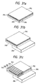
- Figs. 3a to 3f illustrate a method of producing the above-mentioned vibrators.
- a thin coating of a piezoelectric material in paste-like form for example, a titanic-acid/zirconic-acid lead-system composite ceramic material, is applied on a surface plate 20 to thereby form a first piezoelectric material layer 21 (in Fig. 3a).
- a first conducive layer 22 is formed on the surface of the first piezoelectric material layer 21, while a part of the first piezoelectric material layer 21 is left as an exposed portion 21a (in Fig. 3b).
- a thin coating of a piezoelectric material is applied on the respective surfaces of the conductive layer 22 and the exposed portion 21a of the first piezoelectric material layer 21 to thereby form a second piezoelectric material layer 23.
- a conductive layer 24 is further formed on the other surface of the layer 23 opposite the surface on which the conductive layer 21 a has been formed (in Fig. 3c). The above steps are repeated a required number of times.
- the lamination is dried and fired under pressure at a temperature in a range of 1000°C to 1200°C for about an hour, thereby obtaining a plate-like ceramic member 25.
- One end portion of the ceramic member 25 where the conductive layer 24 is exposed is coated with a conductive paintto thereby form a collecting electrode 26, and the other end portion of the ceramic member 25 where the conductive layer 22 is exposed is coated with a conductive paint to thereby form a collecting electrode 27 (in Fig. 3d) to thereby form a piezoelectric plate 28.
- the thus-formed piezoelectric plate 28 is fixed onto the projection portion 2a of the base 2 through a conductive bonding agent (Fig. 3e). Then, the piezoelectric plate 28 is cut, by a diamond cutter or the like, in the vicinity of the surface of the base 2, to thereby divide it in predetermined widths into a plurality of vibrators 30 (in Fig. 3f).
- the piezoelectric vibrators 30 If an electric signal of about 30 V is applied between the conductive members, the piezoelectric vibrators 30 to which the signal is selectively applied through their proper conductive members, expand in their axial directions as a result of application of the actuating voltage to the respective piezoelectric material layers.
- the electrodes are disposed parallel to each other in the expansion direction, the energy efficiency is high in comparison with those of other vibration modes.
- the vibration plate 4 fixed to the top ends of the piezoelectric vibrators 12 expands so that the vibration plate 4 contacting the piezoelectric vibrators 12 is displaced in the direction toward the recess portions 6a constituting the ink reservoirs, thereby compressing the ink reservoirs.
- the ink on which the pressure is exerted through the volume reduction of the ink reservoirs reaches the corresponding nozzle apertures 10 through the penetrating holes 6c and jets out as ink drops.
- the vibration plate 32 fixed to the top ends of the piezoelectric vibrators 12 and 12' expands so that the vibration plate 32 contacting the piezoelectric vibrators is displaced toward the recess portions 33e and 33f of the nozzle plate 33, thereby compressing the ink therein through the vibration plate 32.
- the piezoelectric vibrators 12 contract to their initial states to make the vibration plate 33 return to its initial position, so that the ink reservoir is expanded to the volume at the time of application of no signal. Consequently. the ink in the recess portions 32b to 32e flows into the recess portions 33e and 33f constituting ink reservoirs, thereby preparing for the next ink drop generation. No spacer member is necessary, and it is possible to simplify the assembling process.
- the base plate 44 in this embodiment the piezoelectric elements 45 and 46 expand in the direction of lamination so that the free ends of the piezoelectric elements 45 and 46 press ink toward the nozzle apertures 41 and 42, whereby the dynamically pressurized ink enters the nozzle apertures 41 and 42 and is jetted out as ink drops to thereby form dots on the printing paper.
- the piezoelectric elements 45 and 46 contract into their original states, so that inkflows into the space between the nozzle plate 43 and the piezoelectric elements 45 and 46 to thereby prepare for the next ink drop generation.
- Fig. 9 shows another embodiment of the array of piezoelectric elements according to the present invention.
- inactive layers 76 of a length corresponding to a quarter of the vibration wavelength are formed between a base plate 70 and electrodes 74, which are the closest to the base plate 70, when piezoelectric elements 78 are fixed on the base plate 70 to form a printing head assembly.
- Fig. 10 shows another embodiment of the array of piezoelectric elements according to the present invention.
- a layer 84 of a substance of a high viscoelastic property is interposed between a base plate 80 and an array of piezoelectric elements 82 which are assembled as a printing head, or the piezoelectric elements are fixed to the base plate through a bonding agent which can maintain a high viscoelastic property upon completion of solidification, thereby forming a bonding agent layer.
- Fig. 12 shows an embodiment of the above-mentioned nozzle plate.
- a nozzle plate 92 is constituted in a manner so that a nozzle aperture 89 is formed in the area opposite to free end of each piezoelectric element 88, and an elliptical recess portion 90 is formed so as to surround the nozzle aperture 89.
- ink present in the elliptical recess portion 90 is surrounded by a wall 94 of the recess portion 90 and covered from the backwith the free end of the piezoelectric element 88 upon reception of dynamic pressure caused by elastic waves from the piezoelectric element 88. Its escape path being blocked, the ink concentratedly flows into the nozzle aperture 89. It is therefore possible to jet ink drops effectively with as low applied voltage as possible.
- Fig. 13 shows another embodiment of the nozzle plate.
- a groove 98 having a slightly larger width W than the width W' of each piezoelectric element 96 passes a nozzle aperture 100.
- the piezoelectric element 96 if the piezoelectric element 96 is disposed close enough for its top end to enter the groove 98, elastic waves generated by the piezoelectric element 96 apply a dynamic pressure to ink in the groove 98. Then, since the ink in the groove 98 is surrounded by the walls 102 of the groove 98 and covered from the back with the free end of the piezoelectric element 96, the ink in the groove 98 jets out from the nozzle aperture 100 effectively. When the driving signal is stopped to thereby allow the piezoelectric element 96 to contract, ink flows from a portion not opposite the piezoelectric element in the groove 98 into an area opposite the piezoelectric element, thereby preparing for the next printing operation.
- the width of the groove 98 is larger than that of the piezoelectric element 96 in this embodiment so that the top end of the piezoelectric element 96 can enter the groove 98
- the width W of the groove 98 may be made smaller than the width W' of the piezoelectric element 96 to provide a space between the top end of the piezoelectric element 96 and the surface of the nozzle plate 101. In this case, ink receiving elastic waves from the piezoelectric element 96 is prevented from expanding in the direction parallel to the nozzle plate 101 by the walls 102 of the groove 98, so that it is possible to produce ink drops effectively.
- a plate having such a three-layer structure of a copper plate 114 having a thickness of 50 ⁇ m sandwiched between nickel plates 116 and 118 each having a thickness of 25 ⁇ m it is possible to dissolve all of the nickel plate on one surface of the copper plate at the same time as a recess portion is formed on the other surface, so that it is possible to form a nozzle plate having a groove of 50 ⁇ m in width defining a nozzle aperture.
- Figs. 16 and 17 show another embodiment of the nozzle plate.
- the nozzle plate of this embodiment because of screening the side of piezoelectric elements 128 dynamic pressure caused upon application of a signal to the piezoelectric elements is prevented from propagating to other adjacent nozzle apertures by separation walls 126, so that it is possible to prevent unnecessary ink from flowing out.
- Fig. 18 shows another embodiment according to the present invention.
- struts 130 are formed between piezoelectric elements 132 constituting a piezoelectric element array, and are fixed to a base plate 134 on which the array of piezoelectric elements is mounted, or on a nozzle plate 136.
- a nozzle plate 148 is disposed so as to be in contact with the portions 146 to form struts as shown in Fig. 20, so that it is possible to make the gap between the nozzle plate and the free end of each of the piezoelectric elements be a predetermined size. Accordingly to this embodiment, not only is it possible to form struts in the process of forming an array of piezoelectric elements, but also it is possible to simplify the assembling work because of eliminating the step of attaching the strut members to the base plate.
- Figs. 21a and 21b show another embodiment of the inventive method of fixing a nozzle plate.
- a nozzle plate 150 through which nozzle apertures 152 are bored is urged against a base plate 160 by magnets 156 and 158 or springs so as to be always in contact with the free ends of piezoelectric elements 154.
- a voltage in the direction of contraction is applied to the piezoelectric elements 154 which are in the position of ink drop formation. Consequently, a gap G is produced between the nozzle plate 150 and the free end surfaces of the piezoelectric elements 154 (in Fig. 21b), so that ink flows into this gap. Then, when the application of the signal is stopped, or if a signal in the direction of expansion is applied, the free ends of the piezoelectric elements 154 expand toward the nozzle plate 150.
- the ink in the gap G is pressed to the nozzle aperture 152 and jetted out to the outside as an ink drop. Since the nozzle aperture 152 which has no relationship to the formation of an ink drop is made to elastically contact with the free end of the piezoelectric element 154, dynamic pressure from the adjacent piezoelectric elements does not act on the nozzle aperture 152 so that the ink can be prevented from leaking.
- a bonding agent or resin 162 having low viscosity and high elasticity atthetime of solidification for example, an epoxy-system bonding agent, ultraviolet-ray setting resin such as G11 or G31 made by Asahi Chemical Industry Co., Ltd., or ultraviolet-ray setting silicon rubber such as TUV6000 or TUV 602 made by Toshiba Silicon Co., Ltd., is injected and solidified in portions except for the free end surfaces of the piezoelectric elements 160, as shown in Figs. 22a to 22c, to thereby reduce the influence of the piezoelectric elements 160 to vibration as much as possible, so that it is possible to reinforce the mechanical strength of the piezoelectric elements 160 and more ensure the electric insulation of the conductive layers.
- an epoxy-system bonding agent for example, ultraviolet-ray setting resin such as G11 or G31 made by Asahi Chemical Industry Co., Ltd., or ultraviolet-ray setting silicon rubber such as TUV6000 or TUV 602 made by Toshiba Silicon Co., Ltd.
- nozzle apertures 180 and 182 are formed in opposition to the gaps between the separation wall member 176 and the respective free ends of the piezoelectric elements 172 and 174, and fixed at predetermined intervals through a spacer 184.
- An ink tank 186 communicates with the nozzle apertures 180 and 182 through communication holes 188 and 190.
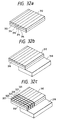
- Figs. 24a to 24c depict a method of forming the above-mentioned piezoelectric element array.
- spacer members 196 and 198 are fixed to a member 194 corresponding to the base plate 166 in Figs. 23a and 23b through a bonding agent (in Fig. 24a).
- piezoelectric element plates 200 and 202 which are the same as those shown in Fig. 3, are fixed at their one ends through a conductive bonding agent so that the conductive layers on their one side are on the side of the spacers 196 and 198 (Fig. 24b).
- a voltage is applied to the respective piezoelectric layers of the piezoelectric elements 172 and 174 through conductive layers 171 and 173 of the piezoelectric element 172 and conductive layers 175 and 177 of the piezoelectric element 174 at the same time, so that the sum of expansion force of the respective piezoelectric layers acts on the free ends. Accordingly, the ink between the separation wall member 176 and the free end of the piezoelectric element 174 is pressed out from the space and jets out to the outside from the nozzle aperture 182. When the application of the voltage to the piezoelectric element 174 is stopped, the piezoelectric element contracts, so that ink flows from the ink tank 186 into the space, thereby preparing for the next dot generation.
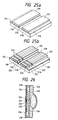
- piezoelectric elements are fixed in the form of a cantilever shape by a spacer in a printing head shown in Figs. 23a and 23b, as shown in Fig. 25a, portions of piezoelectric element plates 210 and 212 projecting over spacers 214 and 216 are fixed to a base plate 220 by a bonding agent or resin 218 having a low viscosity and a high elasticity at the time of solidification, for example, an epoxy-system bonding agent, ultraviolet-ray hardening resin such as G11 and G31 made by Asahi Chemical Industry Co., Ltd., or ultravioletray setting silicon rubber such as TUV6000 or TUV 602 made by Toshiba Silicon Co., Ltd.
- slits 222 are formed at predetermined intervals using a diamond cutter or the like, thereby forming piezoelectric elements 224 and 226, with their one-side surfaces being bonded to the base plate 220 (Fig. 25b).
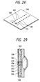
- Figs. 27a to 27c illustrate another embodiment of the inventive method of forming a piezoelectric element array, in which spacers 242 and 244 are fixed to the opposite ends of a base plate 240, and a bonding agent 246 having low viscosity and high elasticity at the time of solidification flows into a grooved portion formed by the spacers 242 and 244 (Fig. 27a).
- a piezoelectric element plate 248 the same as the mentioned above is fixed to the spacers 242 and 244 with a conductive bonding agent and to the base plate 240 with a bonding agent 246 (Fig. 27b).
- a nozzle plate 266 is prepared for the thus-arranged piezoelectric elements, with the nozzle plate 266 arranged by displacing nozzle apertures 262 in the first column and nozzle apertures 264 in the second column from each other by one-half pitch, as shown in Fig. 28.
- the nozzle plate 266 is attached to the base plate 240 (Fig. 27c) through a spacer 268 as shown in Fig. 29, thereby constituting a printing head.
- a partition member and ink channels can be formed together with the formation of piezoelectric elements at the same time, it is possible to simplify the process of production, and it is also possible to improve the density of dots without making the width of the piezoelectric elements narrow.
- the entire large force produced by the thickness-wise vibration of piezoelectric elements is used, and ink is jetted out by the pressure of the piezoelectric elements, so that it is possible to produce ink drops effectively not only in the case of using a normal ink but also in the case of using an extremely high viscous ink such as hot melt ink.
- the piezoelectric element plate 312 and the plate 310 arranged integrally is fixed at its one end portion to a spacer member 318 (in Fig. 32b). Then, slits 320 are formed in the piezoelectric element plate 312 and the plate 310 at regular intervals using a diamond cutter or the like, so as to form stripped lead pieces 322, one ends of which are fixed to the spacer 318 and the other ends of which are free (Fig. 32c).
Landscapes
- Engineering & Computer Science (AREA)
- Manufacturing & Machinery (AREA)
- Particle Formation And Scattering Control In Inkjet Printers (AREA)
- Recording Measured Values (AREA)
Claims (12)
- Tête d'impression à jet d'encre engendrant une gouttelette à la demande comportant :caractérisée parun réseau de plusieurs ouvertures formant buses (10, 10' ; 41, 42 ; 262 ; 280), un réseau de plusieurs éléments piézoélectriques (12, 12' ; 45 ; 46 ; 258, 260) agencés à intervalles réguliers et fixés, au niveau d'une première extrémité de ceux-ci, sur une base (2 ; 44 ; 240 ; 282), les autres extrémités desdits éléments piézoélectriques respectifs (12, 12' ; 45 ; 46 ; 258, 260) étant des extrémités libres qui sont en opposition aux ouvertures respectives desdites ouvertures formant buses (10, 10' ; 41, 42 ; 262 ; 280), des parties formant réservoir d'encre (6a, 6b) étant formées entre lesdites ouvertures formant buses (10, 10' ; 41, 42 ; 262 ; 280) et lesdites extrémités libres,une plaque de vibration (4) entraínée par ledit réseau d'éléments piézoélectriques (12, 12' ; 45, 46 ; 258, 260),
une plaque de buses (8 ; 43 ; 266) ayant ledit réseau dedites plusieurs ouvertures formant buses (10, 10' ; 41 ; 42 ; 262 ; 280)
ladite plaque de vibration (4) étant interposée entre ladite plaque de buses (8 ; 43 ; 266) et ledit réseau d'éléments piézoélectriques, et
lesdits éléments piézoélectriques (12, 12' ; 45 ; 46 ; 258 ; 260) sont formés par découpe en morceaux séparés, à une largeur prédéterminée, d'une plaque piézoélectrique (25 ; 274) obtenue par stratification d'au moins deux couches de matériau piézoélectrique et d'au moins deux couches de matériau conducteur empilées en couches de manière alternée (21, 23, 22 ; 68, 69),
de sorte que les gouttelettes d'encre sont éjectées dans la même direction que la direction de vibration principale de ladite plaque de vibration (4), et
dans lequel ladite plaque de vibration (4) a des parties concaves (4a) au voisinage de parties où la plaque de vibration (4) est en contact avec les éléments piézoélectriques. - Tête d'impression à jet d'encre engendrant une gouttelette sur demande, selon la revendication 1, dans laquelle ladite plaque piézoélectrique est obtenue en chauffant ou brûlant ladite stratification de matériau piézoélectrique et de matériau conducteur empilés en couches de manière alternée (21, 23, 22 ; 68, 69).
- Tête d'impression à jet d'encre engendrant une gouttelette sur demande selon l'une quelconque des revendications précédentes, dans laquelle ladite plaque piézoélectrique est obtenue par chauffage ou combustion d'un stratifié de matériau piézoélectrique analogue à de la pâte et d'un matériau conducteur empilés en couches alternées, (21, 23, 22 ; 68, 69).
- Tête d'impression à jet d'encre engendrant une gouttelette sur demande selon l'une quelconque des revendications 1 à 3, dans laquelle ledit matériau piézoélectrique et ledit matériau conducteur sont stratifiés parallèlement à ladite plaque de vibration (4).
- Procédé pour former des vibrateurs dans une tête d'impression à jet d'encre engendrant une gouttelette sur demande, comportant les étapes consistant à :former une plaque de buses (8 ; 43 ; 266) ayant un réseau de plusieurs ouvertures formant buse (10, 10' ; 41 ; 42 ; 262 ; 280),former un réseau de plusieurs éléments piézoélectriques (12, 12', 45 ; 46 ; 258, 260) agencés à intervalles réguliers et fixés au niveau d'une première extrémité de ceux-ci sur une base (2 ; 44 ; 240 ; 282) à partir d'une stratification d'au moins deux couches de matériau piézoélectrique et d'au moins deux couches de matériau conducteur empilés en couches de manière alternée (21, 23, 22 ; 68, 69) conformément aux'étapes de traitement qui suivent :(a) appliquer un revêtement mince de matériau piézoélectrique sous la forme d'une pâte sur une plaque de surface pour former ainsi une première couche de matériau piézoélectrique,(b) former une première couche conductrice sur la surface de la première couche de matériau piézoélectrique alors qu'une partie de la première couche de matériau piézoélectrique est laissée en tant que partie exposée,(c) appliquer un revêtement mince d'un matériau piézoélectrique sur les surfaces respectives de la première couche conductrice et de la partie exposée de la première couche de matériau piézoélectrique pour former ainsi une seconde couche de matériau piézoélectrique,(d) former une seconde couche conductrice sur l'autre surface de la seconde couche de matériau piézoélectrique opposée à la surface sur laquelle la couche conductrice a été formée,(e) sécher la stratification,(f) chauffer ou brûler la stratification en obtenant ainsi un élément analogue à une plaque,(g) revêtir l'élément analogue à une plaque là où des couches conductrices sont exposées, à l'aide d'une peinture conductrice pour former ainsi des électrodes collectrices pour former ainsi une plaque piézoélectrique,(h) fixer la plaque piézoélectrique sur une base de préférence par l'intermédiaire d'un agent de fixation conducteur, et(i) découper la plaque piézoélectrique au voisinage de la surface de la base, pour la diviser ainsi, en largeurs prédéterminées, en plusieurs vibrateurs,agencer lesdits éléments piézoélectriques (12, 12' ; 45 ; 46 ; 258, 260), de telle sorte que leurs extrémités libres soient situées en opposition aux ouvertures respectives desdites ouvertures formant buse (10, 10' ; 41, 42 ; 262 ; 280), et des parties de réservoir d'encre (6a, 6b) sont formées entre lesdites ouvertures formant buse (10, 10' ; 41 ; 42 ; 262 ; 280) et lesdites extrémités libres,former une plaque de vibration (4) qui est excitée par ledit réseau d'éléments piézoélectriques (12, 12' ; 45, 46 ; 258, 260) et en l'agençant de manière interposée entre ladite plaque de buses (8 ; 43 ; 266) et ledit réseau d'éléments piézoélectriques, de telle sorte que les gouttelettes d'encre sont éjectées dans la même direction que la direction principale de vibration de ladite plaque de vibration (4), et dans lequel ladite plaque a des parties concaves (4a) au voisinage de parties où la plaque de vibration (4) est en contact avec les éléments piézoélectriques.
- Procédé selon la revendication 5, dans lequel les étapes (a) à (d) sont répétées un nombre de fois nécessaire pour obtenir la stratification d'un nombre prédéterminé de couches.
- Procédé selon la revendication 5 ou 6, dans lequel le matériau piézoélectrique est un matériau en céramique composite d'un système plomb-acide titanique ou plomb-acide zirconique.
- Procédé selon l'une quelconque des revendications 5 à 7, dans lequel l'étape (f) est réalisée sous pression.
- Procédé selon l'une quelconque des revendications 5 à 8, dans lequel l'étape (f) est réalisée à une température située dans une plage allant de 1000°C à 1200°C.
- Procédé selon l'une quelconque des revendications 5 à 9, dans lequel l'étape (f) est réalisée pendant environ une heure.
- Procédé selon l'une quelconque des revendications 5 à 10, dans lequel l'élément analogue à une plaque est un élément en céramique.
- Procédé selon l'une quelconque des revendications 5 à 11, dans lequel l'étape (i) est réalisée par un dispositif de découpe à diamant ou analogue.
Priority Applications (4)
| Application Number | Priority Date | Filing Date | Title |
|---|---|---|---|
| EP95102040A EP0655334B2 (fr) | 1990-02-23 | 1991-02-25 | Tête d'impression à jet d'encre générant des gouttelettes à la demande |
| EP95102020A EP0655333B2 (fr) | 1990-02-23 | 1991-02-25 | Tête d'impression à jet d'encre générant des gouttelettes à la demande |
| EP92112945A EP0516188B1 (fr) | 1990-02-23 | 1991-02-25 | Tête d'impression à jet d'encre générant des gouttelettes à la demande |
| EP95108677A EP0678384B1 (fr) | 1990-02-23 | 1991-02-25 | Tête d'impression à jet d'encre générant des gouttelettes à la demande |
Applications Claiming Priority (6)
| Application Number | Priority Date | Filing Date | Title |
|---|---|---|---|
| JP43787/90 | 1990-02-23 | ||
| JP4378790 | 1990-02-23 | ||
| JP4378790 | 1990-02-23 | ||
| JP337278/90 | 1990-11-30 | ||
| JP33727890 | 1990-11-30 | ||
| JP2337278A JP3041952B2 (ja) | 1990-02-23 | 1990-11-30 | インクジェット式記録ヘッド、圧電振動体、及びこれらの製造方法 |
Related Child Applications (3)
| Application Number | Title | Priority Date | Filing Date |
|---|---|---|---|
| EP95108677.6 Division-Into | 1991-02-25 | ||
| EP92112945.8 Division-Into | 1991-02-25 | ||
| EP92112945A Division EP0516188B1 (fr) | 1990-02-23 | 1991-02-25 | Tête d'impression à jet d'encre générant des gouttelettes à la demande |
Publications (4)
| Publication Number | Publication Date |
|---|---|
| EP0443628A2 EP0443628A2 (fr) | 1991-08-28 |
| EP0443628A3 EP0443628A3 (en) | 1992-01-29 |
| EP0443628B1 EP0443628B1 (fr) | 1996-02-07 |
| EP0443628B2 true EP0443628B2 (fr) | 2003-01-02 |
Family
ID=26383619
Family Applications (8)
| Application Number | Title | Priority Date | Filing Date |
|---|---|---|---|
| EP98112293A Expired - Lifetime EP0873872B1 (fr) | 1990-02-23 | 1991-02-25 | Tête d'impression à jet d'encre générant des gouttelettes à la demande |
| EP95102040A Expired - Lifetime EP0655334B2 (fr) | 1990-02-23 | 1991-02-25 | Tête d'impression à jet d'encre générant des gouttelettes à la demande |
| EP01130656A Expired - Lifetime EP1208983B1 (fr) | 1990-02-23 | 1991-02-25 | Tête d'impression jet d'encre générant des gouttelettes sur demande |
| EP02027777A Expired - Lifetime EP1297958B1 (fr) | 1990-02-23 | 1991-02-25 | Tête d'impression jet d'encre générant des gouttelettes sur demande |
| EP92112945A Expired - Lifetime EP0516188B1 (fr) | 1990-02-23 | 1991-02-25 | Tête d'impression à jet d'encre générant des gouttelettes à la demande |
| EP95102020A Expired - Lifetime EP0655333B2 (fr) | 1990-02-23 | 1991-02-25 | Tête d'impression à jet d'encre générant des gouttelettes à la demande |
| EP91102760A Expired - Lifetime EP0443628B2 (fr) | 1990-02-23 | 1991-02-25 | Tête d'impression à jet d'encre générant des gouttelettes à la demande |
| EP00118028A Expired - Lifetime EP1055519B1 (fr) | 1990-02-23 | 1991-02-25 | Tête d'impression à jet d'encre générant des gouttelettes à la demande |
Family Applications Before (6)
| Application Number | Title | Priority Date | Filing Date |
|---|---|---|---|
| EP98112293A Expired - Lifetime EP0873872B1 (fr) | 1990-02-23 | 1991-02-25 | Tête d'impression à jet d'encre générant des gouttelettes à la demande |
| EP95102040A Expired - Lifetime EP0655334B2 (fr) | 1990-02-23 | 1991-02-25 | Tête d'impression à jet d'encre générant des gouttelettes à la demande |
| EP01130656A Expired - Lifetime EP1208983B1 (fr) | 1990-02-23 | 1991-02-25 | Tête d'impression jet d'encre générant des gouttelettes sur demande |
| EP02027777A Expired - Lifetime EP1297958B1 (fr) | 1990-02-23 | 1991-02-25 | Tête d'impression jet d'encre générant des gouttelettes sur demande |
| EP92112945A Expired - Lifetime EP0516188B1 (fr) | 1990-02-23 | 1991-02-25 | Tête d'impression à jet d'encre générant des gouttelettes à la demande |
| EP95102020A Expired - Lifetime EP0655333B2 (fr) | 1990-02-23 | 1991-02-25 | Tête d'impression à jet d'encre générant des gouttelettes à la demande |
Family Applications After (1)
| Application Number | Title | Priority Date | Filing Date |
|---|---|---|---|
| EP00118028A Expired - Lifetime EP1055519B1 (fr) | 1990-02-23 | 1991-02-25 | Tête d'impression à jet d'encre générant des gouttelettes à la demande |
Country Status (5)
| Country | Link |
|---|---|
| US (5) | US5446485A (fr) |
| EP (8) | EP0873872B1 (fr) |
| JP (1) | JP3041952B2 (fr) |
| DE (9) | DE69133583T2 (fr) |
| HK (4) | HK198096A (fr) |
Families Citing this family (149)
| Publication number | Priority date | Publication date | Assignee | Title |
|---|---|---|---|---|
| US6186619B1 (en) | 1990-02-23 | 2001-02-13 | Seiko Epson Corporation | Drop-on-demand ink-jet printing head |
| JP3041952B2 (ja) * | 1990-02-23 | 2000-05-15 | セイコーエプソン株式会社 | インクジェット式記録ヘッド、圧電振動体、及びこれらの製造方法 |
| US6164759A (en) * | 1990-09-21 | 2000-12-26 | Seiko Epson Corporation | Method for producing an electrostatic actuator and an inkjet head using it |
| US6113218A (en) * | 1990-09-21 | 2000-09-05 | Seiko Epson Corporation | Ink-jet recording apparatus and method for producing the head thereof |
| US6168263B1 (en) | 1990-09-21 | 2001-01-02 | Seiko Epson Corporation | Ink jet recording apparatus |
| JP2728980B2 (ja) * | 1991-01-07 | 1998-03-18 | シャープ株式会社 | インクジェットヘッド装置 |
| JP2998764B2 (ja) * | 1991-06-13 | 2000-01-11 | セイコーエプソン株式会社 | インクジェット式印字ヘッド、インク補給方法、及び気泡除去方法 |
| JP3347346B2 (ja) | 1991-09-24 | 2002-11-20 | セイコーエプソン株式会社 | インクジェット記録装置用圧電変位ユニット、及びインクジェット記録装置用記録ヘッド |
| US5510816A (en) * | 1991-11-07 | 1996-04-23 | Seiko Epson Corporation | Method and apparatus for driving ink jet recording head |
| US5764257A (en) * | 1991-12-26 | 1998-06-09 | Seiko Epson Corporation | Ink jet recording head |
| JP3262141B2 (ja) * | 1991-12-26 | 2002-03-04 | セイコーエプソン株式会社 | インクジェット記録ヘッドの駆動回路 |
| JPH06171084A (ja) * | 1992-02-07 | 1994-06-21 | Seiko Epson Corp | インクジェット記録ヘッド |
| JP3147132B2 (ja) * | 1992-03-03 | 2001-03-19 | セイコーエプソン株式会社 | インクジェット記録ヘッド、インクジェット記録ヘッド用振動板、及びインクジェット記録ヘッド用振動板の製造方法 |
| JP3317308B2 (ja) * | 1992-08-26 | 2002-08-26 | セイコーエプソン株式会社 | 積層型インクジェット記録ヘッド、及びその製造方法 |
| JP3144948B2 (ja) * | 1992-05-27 | 2001-03-12 | 日本碍子株式会社 | インクジェットプリントヘッド |
| JP3144949B2 (ja) * | 1992-05-27 | 2001-03-12 | 日本碍子株式会社 | 圧電/電歪アクチュエータ |
| US5424769A (en) * | 1992-06-05 | 1995-06-13 | Seiko Epson Corporation | Ink jet recording head |
| JP3374862B2 (ja) * | 1992-06-12 | 2003-02-10 | セイコーエプソン株式会社 | インクジェット式記録装置 |
| JP3478297B2 (ja) * | 1992-06-26 | 2003-12-15 | セイコーエプソン株式会社 | インクジェット式記録ヘッド |
| JP3495761B2 (ja) * | 1992-07-21 | 2004-02-09 | セイコーエプソン株式会社 | インクジェット式プリンタにおけるインク滴の形成方法、及びインクジェット式記録装置 |
| US6601949B1 (en) | 1992-08-26 | 2003-08-05 | Seiko Epson Corporation | Actuator unit for ink jet recording head |
| EP0608879B1 (fr) * | 1993-01-29 | 1999-10-27 | Canon Kabushiki Kaisha | Appareil à jet d'encre |
| JP3109017B2 (ja) * | 1993-05-12 | 2000-11-13 | セイコーエプソン株式会社 | インクジェット式記録ヘッド |
| US6074048A (en) * | 1993-05-12 | 2000-06-13 | Minolta Co., Ltd. | Ink jet recording head including interengaging piezoelectric and non-piezoelectric members and method of manufacturing same |
| US5729262A (en) * | 1993-08-31 | 1998-03-17 | Ricoh Company, Ltd. | Ink jet head including phase transition material actuators |
| GB2283206B (en) * | 1993-10-07 | 1997-03-19 | Seiko Epson Corp | Piezo-electric driver for an ink jet recording head,and its manufacturing method |
| US5983471A (en) * | 1993-10-14 | 1999-11-16 | Citizen Watch Co., Ltd. | Method of manufacturing an ink-jet head |
| DE69427837T2 (de) * | 1993-10-14 | 2002-04-04 | Citizen Watch Co., Ltd. | Tintenstrahlkopf und Verfahren zu seiner Herstellung und zu seiner Steuerung |
| DE69434514T2 (de) | 1993-12-24 | 2006-06-22 | Seiko Epson Corp. | Tintenstrahlaufzeichnungskopf |
| SG64335A1 (en) * | 1993-12-28 | 1999-04-27 | Seiko Epson Corp | Ink jet recording head |
| JP3043936B2 (ja) * | 1994-02-08 | 2000-05-22 | シャープ株式会社 | インクジェットヘッド |
| JP2721127B2 (ja) * | 1994-03-03 | 1998-03-04 | 富士通株式会社 | インクジェットヘッド |
| FR2717738B1 (fr) * | 1994-03-28 | 1997-10-10 | Seiko Epson Corp | Tête d'enregistrement à jet d'encre. |
| JP3422342B2 (ja) * | 1994-03-28 | 2003-06-30 | セイコーエプソン株式会社 | インクジェツト式記録ヘツド |
| JP3319492B2 (ja) * | 1994-03-28 | 2002-09-03 | セイコーエプソン株式会社 | インクジェットプリンタにおけるヘッド位置調整機構及びヘッド位置調整方法 |
| US5761783A (en) * | 1994-03-29 | 1998-06-09 | Citizen Watch Co., Ltd. | Ink-jet head manufacturing method |
| JPH07329292A (ja) * | 1994-04-13 | 1995-12-19 | Seiko Epson Corp | インクジェット式記録ヘッド |
| WO1996000151A1 (fr) * | 1994-06-23 | 1996-01-04 | Citizen Watch Co., Ltd. | Actionneur piezo-electrique pour tete d'impression a jet d'encre et son procede de fabrication |
| US5818482A (en) * | 1994-08-22 | 1998-10-06 | Ricoh Company, Ltd. | Ink jet printing head |
| WO1996009170A1 (fr) * | 1994-09-23 | 1996-03-28 | Dataproducts Corporation | Appareil d'impression a chambres a jet d'encre utilisant une pluralite d'orifices |
| JP3484841B2 (ja) * | 1994-09-26 | 2004-01-06 | セイコーエプソン株式会社 | インクジェット式記録ヘッド |
| WO1996014987A1 (fr) * | 1994-11-14 | 1996-05-23 | Philips Electronics N.V. | Dispositif d'enregistrement a jet d'encre |
| JPH09507804A (ja) * | 1994-11-14 | 1997-08-12 | フィリップス エレクトロニクス ネムローゼ フェンノートシャップ | インクジェット記録装置及びインクジェット記録ヘッド |
| CH688960A5 (de) * | 1994-11-24 | 1998-06-30 | Pelikan Produktions Ag | Tropfenerzeuger fuer Mikrotropfen, insbesondere fuer einen Ink-Jet-Printer. |
| KR100417754B1 (ko) * | 1994-12-05 | 2004-06-30 | 코닌클리케 필립스 일렉트로닉스 엔.브이. | 잉크젯기록장치 |
| JPH08187848A (ja) * | 1995-01-12 | 1996-07-23 | Brother Ind Ltd | 積層式圧電素子およびその製造方法 |
| JPH08192514A (ja) * | 1995-01-19 | 1996-07-30 | Brother Ind Ltd | インクジェット記録装置 |
| JPH08252920A (ja) * | 1995-03-16 | 1996-10-01 | Brother Ind Ltd | 積層型圧電素子の製造方法 |
| JPH08279631A (ja) * | 1995-04-05 | 1996-10-22 | Brother Ind Ltd | 積層型圧電素子の製造方法 |
| JPH08336966A (ja) * | 1995-06-15 | 1996-12-24 | Minolta Co Ltd | インクジェット記録装置 |
| EP0755790A1 (fr) | 1995-07-25 | 1997-01-29 | Koninklijke Philips Electronics N.V. | Dispositif d'enregistrement à jet d'encre |
| US6729002B1 (en) | 1995-09-05 | 2004-05-04 | Seiko Epson Corporation | Method of producing an ink jet recording head |
| DE69625296T2 (de) * | 1995-09-05 | 2003-07-17 | Seiko Epson Corp., Tokio/Tokyo | Tintenstrahlaufzeichnungskopf und sein Herstellungsverfahren |
| EP0799134A1 (fr) * | 1995-10-23 | 1997-10-08 | Koninklijke Philips Electronics N.V. | Dispositif enregistreur a jet d'encre |
| JP3516284B2 (ja) * | 1995-12-21 | 2004-04-05 | 富士写真フイルム株式会社 | 液体噴射装置 |
| US6016024A (en) * | 1996-04-05 | 2000-01-18 | Murata Manufacturing Co., Ltd. | Piezoelectric component |
| JP3271517B2 (ja) * | 1996-04-05 | 2002-04-02 | 株式会社村田製作所 | 圧電共振子およびそれを用いた電子部品 |
| JP3266031B2 (ja) * | 1996-04-18 | 2002-03-18 | 株式会社村田製作所 | 圧電共振子およびそれを用いた電子部品 |
| US5939819A (en) * | 1996-04-18 | 1999-08-17 | Murata Manufacturing Co., Ltd. | Electronic component and ladder filter |
| JPH09300608A (ja) * | 1996-05-09 | 1997-11-25 | Minolta Co Ltd | インクジェット記録ヘッド |
| US6074047A (en) * | 1996-05-21 | 2000-06-13 | Minolta Co., Ltd. | Ink-jet recording head |
| DE19626428A1 (de) * | 1996-07-01 | 1998-01-15 | Heinzl Joachim | Tröpfchenwolkenerzeuger |
| JPH1079639A (ja) * | 1996-07-10 | 1998-03-24 | Murata Mfg Co Ltd | 圧電共振子およびそれを用いた電子部品 |
| JPH1084244A (ja) * | 1996-07-18 | 1998-03-31 | Murata Mfg Co Ltd | 圧電共振子およびそれを用いた電子部品 |
| JP3271541B2 (ja) * | 1996-07-26 | 2002-04-02 | 株式会社村田製作所 | 圧電共振子およびそれを用いた電子部品 |
| US6305791B1 (en) | 1996-07-31 | 2001-10-23 | Minolta Co., Ltd. | Ink-jet recording device |
| JP3577170B2 (ja) * | 1996-08-05 | 2004-10-13 | 株式会社村田製作所 | 圧電共振子とその製造方法およびそれを用いた電子部品 |
| JPH10107579A (ja) * | 1996-08-06 | 1998-04-24 | Murata Mfg Co Ltd | 圧電部品 |
| JPH10126203A (ja) * | 1996-08-27 | 1998-05-15 | Murata Mfg Co Ltd | 圧電共振子およびそれを用いた電子部品 |
| GB9617908D0 (en) * | 1996-08-28 | 1996-10-09 | Videojet Systems Int | A droplet generator for a continuous stream ink jet print head |
| JP3267171B2 (ja) * | 1996-09-12 | 2002-03-18 | 株式会社村田製作所 | 圧電共振子およびそれを用いた電子部品 |
| JPH10126202A (ja) * | 1996-10-23 | 1998-05-15 | Murata Mfg Co Ltd | 圧電共振子およびそれを用いた電子部品 |
| WO1998022288A1 (fr) * | 1996-11-18 | 1998-05-28 | Seiko Epson Corporation | Tete d'ecriture a jet d'encre |
| JP3271538B2 (ja) * | 1996-11-28 | 2002-04-02 | 株式会社村田製作所 | 圧電共振子およびそれを用いた電子部品 |
| JPH10202856A (ja) * | 1997-01-20 | 1998-08-04 | Minolta Co Ltd | インクジェット記録ヘッド |
| JPH10202921A (ja) * | 1997-01-22 | 1998-08-04 | Minolta Co Ltd | インクジェット記録ヘッド |
| US6053600A (en) * | 1997-01-22 | 2000-04-25 | Minolta Co., Ltd. | Ink jet print head having homogeneous base plate and a method of manufacture |
| JPH10211704A (ja) | 1997-01-31 | 1998-08-11 | Minolta Co Ltd | インクジェットヘッドおよびインクジェットヘッド用インク室形成部材の製造方法 |
| JP3627782B2 (ja) * | 1997-02-28 | 2005-03-09 | リコープリンティングシステムズ株式会社 | オンデマンド型マルチノズルインクジェットヘッド |
| JPH10296971A (ja) | 1997-04-23 | 1998-11-10 | Minolta Co Ltd | インクジェット記録装置 |
| US6338549B1 (en) | 1997-06-27 | 2002-01-15 | Seiko Epson Corporation | Piezoelectric vibrator unit, method for manufacturing the same, and ink-jet recording head |
| US6299295B1 (en) * | 1997-07-03 | 2001-10-09 | Matsushita Electric Industrial Co., Ltd. | Ink jet printing head having ink chambers arranged in succession by lamination |
| JP3456380B2 (ja) * | 1997-09-02 | 2003-10-14 | 株式会社村田製作所 | 圧電アクチュエータ |
| JPH11168246A (ja) * | 1997-09-30 | 1999-06-22 | Matsushita Electric Ind Co Ltd | 圧電アクチュエータ、赤外線センサおよび圧電光偏向器 |
| US6572221B1 (en) | 1997-10-10 | 2003-06-03 | Xaar Technology Limited | Droplet deposition apparatus for ink jet printhead |
| GB9721555D0 (en) * | 1997-10-10 | 1997-12-10 | Xaar Technology Ltd | Droplet deposition apparatus and methods of manufacture thereof |
| JP3381779B2 (ja) | 1998-09-17 | 2003-03-04 | セイコーエプソン株式会社 | 圧電振動子ユニット、圧電振動子ユニットの製造方法、及びインクジェット式記録ヘッド |
| US6417600B2 (en) | 1998-09-17 | 2002-07-09 | Seiko Epson Corporation | Piezoelectric vibrator unit, method for manufacturing the same, and ink jet recording head comprising the same |
| US6497476B1 (en) | 1998-10-12 | 2002-12-24 | Matsushita Electric Industrial Co., Ltd. | Liquid injection device, manufacturing method therefor, liquid injection method and manufacturing method for piezo-electric actuator |
| IL127484A (en) | 1998-12-09 | 2001-06-14 | Aprion Digital Ltd | Laser container printing method and method |
| JP4240245B2 (ja) * | 1998-12-15 | 2009-03-18 | 富士フイルム株式会社 | インクジェットプリンタヘッド及びインクジェットプリンタ |
| US6161270A (en) * | 1999-01-29 | 2000-12-19 | Eastman Kodak Company | Making printheads using tapecasting |
| JP2000218787A (ja) | 1999-01-29 | 2000-08-08 | Seiko Epson Corp | インクジェット式記録ヘッド及び画像記録装置 |
| US6168746B1 (en) | 1999-02-22 | 2001-01-02 | Eastman Kodak Company | Injection molding of ferroelectric articles |
| US6578953B2 (en) | 1999-03-29 | 2003-06-17 | Seiko Epson Corporation | Inkjet recording head, piezoelectric vibration element unit used for the recording head, and method of manufacturing the piezoelectric vibration element unit |
| US6254819B1 (en) | 1999-07-16 | 2001-07-03 | Eastman Kodak Company | Forming channel members for ink jet printheads |
| US6398350B2 (en) * | 2000-02-08 | 2002-06-04 | Seiko Epson Corporation | Piezoelectric vibrator unit, liquid jet head, manufacturing method of piezoelectric vibrator unit, and manufacturing method of liquid jet head |
| US6350014B1 (en) | 2000-03-01 | 2002-02-26 | Eastman Kodak Company | Apparatus for using nanoparticles for printing images |
| US6361161B1 (en) | 2000-03-01 | 2002-03-26 | Eastman Kodak Company | Nanoparticles for printing images |
| US6474785B1 (en) | 2000-09-05 | 2002-11-05 | Hewlett-Packard Company | Flextensional transducer and method for fabrication of a flextensional transducer |
| JP4639492B2 (ja) * | 2001-02-23 | 2011-02-23 | セイコーエプソン株式会社 | インクジェット式記録ヘッド及びインクジェット式記録装置 |
| EP1364793B1 (fr) * | 2001-03-01 | 2009-07-15 | Ngk Insulators, Ltd. | Actionneur piezo-electrique en forme de peigne et son procede de fabrication |
| DE10206115A1 (de) * | 2001-03-06 | 2002-09-19 | Ceramtec Ag | Piezokeramische Vielschichtaktoren sowie ein Verfahren zu ihrer Herstellung |
| JP4710042B2 (ja) * | 2001-03-08 | 2011-06-29 | リコープリンティングシステムズ株式会社 | インクジェットプリントヘッド及びその製造方法 |
| US6540339B2 (en) | 2001-03-21 | 2003-04-01 | Hewlett-Packard Company | Flextensional transducer assembly including array of flextensional transducers |
| US6474787B2 (en) | 2001-03-21 | 2002-11-05 | Hewlett-Packard Company | Flextensional transducer |
| US6673388B2 (en) | 2001-04-27 | 2004-01-06 | Eastman Kodak Company | Method of making a printed circuit board |
| JP2002361862A (ja) * | 2001-06-01 | 2002-12-18 | Hitachi Koki Co Ltd | インクジェットプリントヘッド |
| US6478401B1 (en) | 2001-07-06 | 2002-11-12 | Lexmark International, Inc. | Method for determining vertical misalignment between printer print heads |
| US6505917B1 (en) | 2001-07-13 | 2003-01-14 | Illinois Tool Works Inc. | Electrode patterns for piezo-electric ink jet printer |
| US6428140B1 (en) | 2001-09-28 | 2002-08-06 | Hewlett-Packard Company | Restriction within fluid cavity of fluid drop ejector |
| US6685302B2 (en) | 2001-10-31 | 2004-02-03 | Hewlett-Packard Development Company, L.P. | Flextensional transducer and method of forming a flextensional transducer |
| US6601948B1 (en) | 2002-01-18 | 2003-08-05 | Illinois Tool Works, Inc. | Fluid ejecting device with drop volume modulation capabilities |
| NL1021010C2 (nl) | 2002-07-05 | 2004-01-06 | Oce Tech Bv | Werkwijze voor het bedrukken van een ontvangstmateriaal met hot melt inkt en een inkjet printer geschikt om deze werkwijze toe te passen. |
| GB2391871A (en) * | 2002-08-16 | 2004-02-18 | Qinetiq Ltd | Depositing conductive solid materials using reservoirs in a printhead |
| US6883903B2 (en) | 2003-01-21 | 2005-04-26 | Martha A. Truninger | Flextensional transducer and method of forming flextensional transducer |
| US7131718B2 (en) * | 2003-06-20 | 2006-11-07 | Ricoh Printing Systems, Ltd. | Inkjet head and ejection device |
| US20050068379A1 (en) * | 2003-09-30 | 2005-03-31 | Fuji Photo Film Co., Ltd. | Droplet discharge head and inkjet recording apparatus |
| WO2005065954A1 (fr) * | 2003-12-30 | 2005-07-21 | Applera Corporation | Appareils et procedes permettant de deposer des fluides |
| US7118192B2 (en) * | 2004-01-21 | 2006-10-10 | Silverbrook Research Pty Ltd | Printhead assembly with support for print engine controller |
| US7219980B2 (en) * | 2004-01-21 | 2007-05-22 | Silverbrook Research Pty Ltd | Printhead assembly with removable cover |
| US7108353B2 (en) * | 2004-01-21 | 2006-09-19 | Silverbrook Research Pty Ltd | Printhead assembly with floating components |
| US7401894B2 (en) * | 2004-01-21 | 2008-07-22 | Silverbrook Research Pty Ltd | Printhead assembly with electrically interconnected print engine controllers |
| US7083257B2 (en) * | 2004-01-21 | 2006-08-01 | Silverbrook Research Pty Ltd | Printhead assembly with sealed fluid delivery channels |
| US7367649B2 (en) * | 2004-01-21 | 2008-05-06 | Silverbrook Research Pty Ltd | Printhead assembly with selectable printhead integrated circuit control |
| US7156489B2 (en) * | 2004-01-21 | 2007-01-02 | Silverbrook Research Pty Ltd | Printhead assembly with clamped printhead integrated circuits |
| US7083271B2 (en) * | 2004-01-21 | 2006-08-01 | Silverbrook Research Pty Ltd | Printhead module with laminated fluid distribution stack |
| US7201469B2 (en) * | 2004-01-21 | 2007-04-10 | Silverbrook Research Pty Ltd | Printhead assembly |
| US7438385B2 (en) * | 2004-01-21 | 2008-10-21 | Silverbrook Research Pty Ltd | Printhead assembly with interconnected printhead modules |
| US7159972B2 (en) * | 2004-01-21 | 2007-01-09 | Silverbrook Research Pty Ltd | Printhead module having selectable number of fluid channels |
| US7258422B2 (en) * | 2004-01-21 | 2007-08-21 | Silverbrook Research Pty Ltd | Printhead assembly with fluid supply connections |
| US7090336B2 (en) * | 2004-01-21 | 2006-08-15 | Silverbrook Research Pty Ltd | Printhead assembly with constrained printhead integrated circuits |
| US7416274B2 (en) * | 2004-01-21 | 2008-08-26 | Silverbrook Research Pty Ltd | Printhead assembly with print engine controller |
| US7213906B2 (en) * | 2004-01-21 | 2007-05-08 | Silverbrook Research Pty Ltd | Printhead assembly relatively free from environmental effects |
| US7178901B2 (en) * | 2004-01-21 | 2007-02-20 | Silverbrook Research Pty Ltd | Printhead assembly with dual power supply |
| US7077505B2 (en) | 2004-01-21 | 2006-07-18 | Silverbrook Research Pty Ltd | Printhead assembly with common printhead integrated circuit and print engine controller power input |
| US7198355B2 (en) * | 2004-01-21 | 2007-04-03 | Silverbrook Research Pty Ltd | Printhead assembly with mounting element for power input |
| US7591533B2 (en) * | 2004-01-21 | 2009-09-22 | Silverbrook Research Pty Ltd | Printhead assembly with print media guide |
| US7077504B2 (en) * | 2004-01-21 | 2006-07-18 | Silverbrook Research Pty Ltd | Printhead assembly with loaded electrical connections |
| US7322672B2 (en) * | 2004-01-21 | 2008-01-29 | Silverbrook Research Pty Ltd | Printhead assembly with combined securing and mounting arrangement for components |
| JP2005270743A (ja) * | 2004-03-23 | 2005-10-06 | Toshiba Corp | インクジェットヘッド |
| US7401885B2 (en) * | 2004-08-23 | 2008-07-22 | Semiconductor Energy Laboratory Co., Ltd. | Droplet discharge apparatus |
| JP2008114561A (ja) * | 2006-11-08 | 2008-05-22 | Ricoh Co Ltd | 液体吐出ヘッド、液体吐出装置、画像形成装置 |
| JP5338253B2 (ja) * | 2008-02-14 | 2013-11-13 | セイコーエプソン株式会社 | 液体噴射ヘッドの製造方法及び液体噴射ヘッド並びに液体噴射装置 |
| JP5446582B2 (ja) * | 2008-11-19 | 2014-03-19 | セイコーエプソン株式会社 | 液体噴射ヘッド、及び、液体噴射装置 |
| US8490331B2 (en) * | 2009-09-11 | 2013-07-23 | Cgi Windows & Doors | Roller for a sliding panel assembly, and method of installing a sliding panel assembly |
| US9832528B2 (en) | 2010-10-21 | 2017-11-28 | Sony Corporation | System and method for merging network-based content with broadcasted programming content |
| EP3099490B1 (fr) | 2014-01-27 | 2020-08-12 | HP Indigo B.V. | Clapet |
| GB201518337D0 (en) * | 2015-10-16 | 2015-12-02 | The Technology Partnership Plc | Linear device |
Family Cites Families (45)
| Publication number | Priority date | Publication date | Assignee | Title |
|---|---|---|---|---|
| US3679950A (en) † | 1971-04-16 | 1972-07-25 | Nl Industries Inc | Ceramic capacitors |
| DE2527647C3 (de) † | 1975-06-20 | 1981-06-25 | Siemens AG, 1000 Berlin und 8000 München | Mit Flüssigkeitströpfchen arbeitendes Schreibgerät |
| US4367478A (en) † | 1979-04-25 | 1983-01-04 | Xerox Corporation | Pressure pulse drop ejector apparatus |
| JPS56120365A (en) * | 1980-02-28 | 1981-09-21 | Seiko Epson Corp | Ink jet head |
| US4459601A (en) † | 1981-01-30 | 1984-07-10 | Exxon Research And Engineering Co. | Ink jet method and apparatus |
| US4390886A (en) * | 1981-09-25 | 1983-06-28 | Xerox Corporation | Ink jet printing machine |
| US4443729A (en) * | 1981-06-22 | 1984-04-17 | Rockwell International Corporation | Piezoceramic bender element having an electrode arrangement suppressing signal development in mount region |
| FR2508709A1 (fr) * | 1981-06-30 | 1982-12-31 | Thomson Csf | Detecteur photonique a lecture a transfert de charges a l'etat solide, et cible de prise de vues utilisant un tel detecteur |
| JPS58108163A (ja) * | 1981-12-22 | 1983-06-28 | Seiko Epson Corp | インクジェットヘッドの製造方法 |
| US4646106A (en) * | 1982-01-04 | 1987-02-24 | Exxon Printing Systems, Inc. | Method of operating an ink jet |
| US4418355A (en) * | 1982-01-04 | 1983-11-29 | Exxon Research And Engineering Co. | Ink jet apparatus with preloaded diaphragm and method of making same |
| US4439780A (en) * | 1982-01-04 | 1984-03-27 | Exxon Research And Engineering Co. | Ink jet apparatus with improved transducer support |
| JPS58119871A (ja) * | 1982-01-04 | 1983-07-16 | データプロダクツ コーポレイション | インクジエツト装置 |
| EP0094078B1 (fr) * | 1982-05-11 | 1988-11-02 | Nec Corporation | Elément électrostrictif multicouche résistant à l'application répétée d'impulsions |
| JPS59152708A (ja) * | 1983-02-20 | 1984-08-31 | Murata Mfg Co Ltd | 圧電共振子の製造方法 |
| DE3306098A1 (de) * | 1983-02-22 | 1984-08-23 | Siemens AG, 1000 Berlin und 8000 München | Piezoelektrisch betriebener schreibkopf mit kanalmatrize |
| DE3317082A1 (de) | 1983-05-10 | 1984-11-15 | Siemens AG, 1000 Berlin und 8000 München | Mit fluessigkeitstroepfchen arbeitendes schreibgeraet |
| JPS608953A (ja) | 1983-06-29 | 1985-01-17 | Omron Tateisi Electronics Co | プログラム・アナライザ |
| JPS6090770A (ja) * | 1983-10-25 | 1985-05-21 | Seiko Epson Corp | インクジェットヘッド |
| DE3342844A1 (de) * | 1983-11-26 | 1985-06-05 | Philips Patentverwaltung Gmbh, 2000 Hamburg | Mikroplanarer tintenstrahldruckkopf |
| JPS612376A (ja) * | 1984-06-14 | 1986-01-08 | Ngk Spark Plug Co Ltd | シ−ト状圧電体 |
| JPS6146082A (ja) * | 1984-08-10 | 1986-03-06 | Nippon Telegr & Teleph Corp <Ntt> | 圧電アクチユエ−タ |
| JPS61208880A (ja) * | 1985-03-14 | 1986-09-17 | Nec Corp | 電歪効果素子の製造方法 |
| US4641153A (en) * | 1985-09-03 | 1987-02-03 | Pitney Bowes Inc. | Notched piezo-electric transducer for an ink jet device |
| DE3645017C2 (fr) * | 1985-09-06 | 1990-07-12 | Fuji Electric Co., Ltd., Kawasaki, Kanagawa, Jp | |
| US4752789A (en) * | 1986-07-25 | 1988-06-21 | Dataproducts Corporation | Multi-layer transducer array for an ink jet apparatus |
| US4803763A (en) * | 1986-08-28 | 1989-02-14 | Nippon Soken, Inc. | Method of making a laminated piezoelectric transducer |
| DE3751183T2 (de) * | 1986-09-29 | 1995-11-16 | Mitsubishi Chem Corp | Piezoelektrischer Antrieb. |
| JPS63125343A (ja) * | 1986-11-14 | 1988-05-28 | Canon Inc | 記録ヘツド |
| JPS63128778A (ja) * | 1986-11-19 | 1988-06-01 | Nec Corp | 電歪効果素子 |
| US4729058A (en) † | 1986-12-11 | 1988-03-01 | Aluminum Company Of America | Self-limiting capacitor formed using a plurality of thin film semiconductor ceramic layers |
| JPS63185640A (ja) * | 1987-01-28 | 1988-08-01 | Nec Corp | インクジエツト記録装置 |
| US4788557A (en) * | 1987-03-09 | 1988-11-29 | Dataproducts Corporation | Ink jet method and apparatus for reducing cross talk |
| JPH066374B2 (ja) * | 1987-05-27 | 1994-01-26 | 株式会社トーキン | 積層形圧電変位素子 |
| JPS63303750A (ja) * | 1987-06-03 | 1988-12-12 | Ricoh Co Ltd | インクジエツトヘツド |
| JP2695418B2 (ja) * | 1987-10-30 | 1997-12-24 | 株式会社リコー | オンデマンド型インクジェットヘッド |
| JPH01198357A (ja) * | 1988-02-02 | 1989-08-09 | Nec Corp | インク噴射機構 |
| JP2806386B2 (ja) * | 1988-02-16 | 1998-09-30 | 富士電機株式会社 | インクジェット記録ヘッド |
| JPH01255549A (ja) * | 1988-04-06 | 1989-10-12 | Seiko Epson Corp | インクジェットヘッド |
| US4962391A (en) * | 1988-04-12 | 1990-10-09 | Seiko Epson Corporation | Ink jet printer head |
| JPH022006A (ja) * | 1988-06-13 | 1990-01-08 | Fuji Electric Co Ltd | インクジェット記録ヘッド |
| DE68906001T2 (de) * | 1988-12-07 | 1993-09-09 | Seiko Epson Corp | Auf abruf arbeitender tintenstrahldruckkopf. |
| JPH0733087B2 (ja) * | 1989-06-09 | 1995-04-12 | シャープ株式会社 | インクジェットプリンタ |
| JP3041952B2 (ja) * | 1990-02-23 | 2000-05-15 | セイコーエプソン株式会社 | インクジェット式記録ヘッド、圧電振動体、及びこれらの製造方法 |
| JPH0690770A (ja) * | 1991-03-29 | 1994-04-05 | Shimadzu Corp | マイクロマニピュレータ用微小器具 |
-
1990
- 1990-11-30 JP JP2337278A patent/JP3041952B2/ja not_active Expired - Lifetime
-
1991
- 1991-02-25 DE DE69133583T patent/DE69133583T2/de not_active Expired - Lifetime
- 1991-02-25 EP EP98112293A patent/EP0873872B1/fr not_active Expired - Lifetime
- 1991-02-25 DE DE69133061T patent/DE69133061T2/de not_active Expired - Fee Related
- 1991-02-25 EP EP95102040A patent/EP0655334B2/fr not_active Expired - Lifetime
- 1991-02-25 DE DE69132740T patent/DE69132740T2/de not_active Expired - Fee Related
- 1991-02-25 EP EP01130656A patent/EP1208983B1/fr not_active Expired - Lifetime
- 1991-02-25 EP EP02027777A patent/EP1297958B1/fr not_active Expired - Lifetime
- 1991-02-25 DE DE69130837T patent/DE69130837T3/de not_active Expired - Fee Related
- 1991-02-25 DE DE69120806T patent/DE69120806T2/de not_active Expired - Fee Related
- 1991-02-25 DE DE69133469T patent/DE69133469T2/de not_active Expired - Fee Related
- 1991-02-25 EP EP92112945A patent/EP0516188B1/fr not_active Expired - Lifetime
- 1991-02-25 DE DE69116900T patent/DE69116900T3/de not_active Expired - Lifetime
- 1991-02-25 EP EP95102020A patent/EP0655333B2/fr not_active Expired - Lifetime
- 1991-02-25 DE DE69127378T patent/DE69127378T2/de not_active Expired - Fee Related
- 1991-02-25 EP EP91102760A patent/EP0443628B2/fr not_active Expired - Lifetime
- 1991-02-25 EP EP00118028A patent/EP1055519B1/fr not_active Expired - Lifetime
- 1991-02-25 DE DE69126997T patent/DE69126997T3/de not_active Expired - Fee Related
-
1992
- 1992-07-31 US US07/922,378 patent/US5446485A/en not_active Expired - Lifetime
-
1993
- 1993-10-14 US US08/136,049 patent/US5444471A/en not_active Expired - Lifetime
-
1995
- 1995-02-24 US US08/393,920 patent/US5910809A/en not_active Expired - Lifetime
- 1995-05-04 US US08/433,756 patent/US5600357A/en not_active Expired - Lifetime
-
1996
- 1996-10-31 HK HK198096A patent/HK198096A/en not_active IP Right Cessation
-
1997
- 1997-02-03 US US08/794,017 patent/US5894317A/en not_active Expired - Fee Related
- 1997-06-26 HK HK129997A patent/HK129997A/en not_active IP Right Cessation
- 1997-10-24 HK HK97102023A patent/HK1000572A1/en not_active IP Right Cessation
-
2002
- 2002-08-21 HK HK02106129.9A patent/HK1044511A1/en unknown
Also Published As
Similar Documents
| Publication | Publication Date | Title |
|---|---|---|
| EP0443628B2 (fr) | Tête d'impression à jet d'encre générant des gouttelettes à la demande | |
| HK1000572B (en) | Drop-on-demand ink-jet printing head | |
| US6742875B2 (en) | Drop-on-demand ink-jet printing head | |
| US6039440A (en) | Ink-jet head | |
| EP0678384B1 (fr) | Tête d'impression à jet d'encre générant des gouttelettes à la demande | |
| HK1000440B (en) | Drop-on-demand ink-jet printing head | |
| HK1051989A (en) | Drop-on-demand ink-jet printing head | |
| HK1002427B (en) | Drop-on-demand ink jet printing head | |
| JP3578190B2 (ja) | インクジェット式記録ヘッド駆動用圧電振動子ユニット、及びその製造方法 | |
| JP2959056B2 (ja) | インクジェット式印字ヘッド | |
| JP2858956B2 (ja) | インクジェットヘッド及びその製造方法 | |
| JP2785720B2 (ja) | インクジェット式印字ヘッド | |
| JPH0499638A (ja) | インクジェット式印字ヘッド |
Legal Events
| Date | Code | Title | Description |
|---|---|---|---|
| PUAI | Public reference made under article 153(3) epc to a published international application that has entered the european phase |
Free format text: ORIGINAL CODE: 0009012 |
|
| AK | Designated contracting states |
Kind code of ref document: A2 Designated state(s): DE FR GB |
|
| PUAL | Search report despatched |
Free format text: ORIGINAL CODE: 0009013 |
|
| AK | Designated contracting states |
Kind code of ref document: A3 Designated state(s): DE FR GB |
|
| 17P | Request for examination filed |
Effective date: 19920729 |
|
| 17Q | First examination report despatched |
Effective date: 19931206 |
|
| GRAA | (expected) grant |
Free format text: ORIGINAL CODE: 0009210 |
|
| AK | Designated contracting states |
Kind code of ref document: B1 Designated state(s): DE FR GB |
|
| XX | Miscellaneous (additional remarks) |
Free format text: TEILANMELDUNGEN 92112945.8 UND 95108677.6. |
|
| REF | Corresponds to: |
Ref document number: 69116900 Country of ref document: DE Date of ref document: 19960321 |
|
| ET | Fr: translation filed | ||
| PLBI | Opposition filed |
Free format text: ORIGINAL CODE: 0009260 |
|
| PLBF | Reply of patent proprietor to notice(s) of opposition |
Free format text: ORIGINAL CODE: EPIDOS OBSO |
|
| PLBQ | Unpublished change to opponent data |
Free format text: ORIGINAL CODE: EPIDOS OPPO |
|
| PLAB | Opposition data, opponent's data or that of the opponent's representative modified |
Free format text: ORIGINAL CODE: 0009299OPPO |
|
| 26 | Opposition filed |
Opponent name: OCE-NEDERLAND B.V. Effective date: 19961107 |
|
| R26 | Opposition filed (corrected) |
Opponent name: OCE-NEDERLAND B.V. Effective date: 19961107 |
|
| PLBF | Reply of patent proprietor to notice(s) of opposition |
Free format text: ORIGINAL CODE: EPIDOS OBSO |
|
| PLBF | Reply of patent proprietor to notice(s) of opposition |
Free format text: ORIGINAL CODE: EPIDOS OBSO |
|
| PLAW | Interlocutory decision in opposition |
Free format text: ORIGINAL CODE: EPIDOS IDOP |
|
| APAC | Appeal dossier modified |
Free format text: ORIGINAL CODE: EPIDOS NOAPO |
|
| APAE | Appeal reference modified |
Free format text: ORIGINAL CODE: EPIDOS REFNO |
|
| APAC | Appeal dossier modified |
Free format text: ORIGINAL CODE: EPIDOS NOAPO |
|
| REG | Reference to a national code |
Ref country code: GB Ref legal event code: IF02 |
|
| APAC | Appeal dossier modified |
Free format text: ORIGINAL CODE: EPIDOS NOAPO |
|
| RAP2 | Party data changed (patent owner data changed or rights of a patent transferred) |
Owner name: SEIKO EPSON CORPORATION |
|
| PLAW | Interlocutory decision in opposition |
Free format text: ORIGINAL CODE: EPIDOS IDOP |
|
| PUAH | Patent maintained in amended form |
Free format text: ORIGINAL CODE: 0009272 |
|
| STAA | Information on the status of an ep patent application or granted ep patent |
Free format text: STATUS: PATENT MAINTAINED AS AMENDED |
|
| 27A | Patent maintained in amended form |
Effective date: 20030102 |
|
| AK | Designated contracting states |
Kind code of ref document: B2 Designated state(s): DE FR GB |
|
| XX | Miscellaneous (additional remarks) |
Free format text: TEILANMELDUNGEN 92112945.8 UND 95108677.6. |
|
| ET3 | Fr: translation filed ** decision concerning opposition | ||
| APAH | Appeal reference modified |
Free format text: ORIGINAL CODE: EPIDOSCREFNO |
|
| PGFP | Annual fee paid to national office [announced via postgrant information from national office to epo] |
Ref country code: FR Payment date: 20100223 Year of fee payment: 20 |
|
| PGFP | Annual fee paid to national office [announced via postgrant information from national office to epo] |
Ref country code: GB Payment date: 20100202 Year of fee payment: 20 Ref country code: DE Payment date: 20100303 Year of fee payment: 20 |
|
| REG | Reference to a national code |
Ref country code: DE Ref legal event code: R071 Ref document number: 69116900 Country of ref document: DE |
|
| REG | Reference to a national code |
Ref country code: GB Ref legal event code: PE20 Expiry date: 20110224 |
|
| PG25 | Lapsed in a contracting state [announced via postgrant information from national office to epo] |
Ref country code: GB Free format text: LAPSE BECAUSE OF EXPIRATION OF PROTECTION Effective date: 20110224 |
|
| PG25 | Lapsed in a contracting state [announced via postgrant information from national office to epo] |
Ref country code: DE Free format text: LAPSE BECAUSE OF EXPIRATION OF PROTECTION Effective date: 20110225 |