EP0443634B1 - Distributeur d'engrais centrifuge avec trémie - Google Patents
Distributeur d'engrais centrifuge avec trémie Download PDFInfo
- Publication number
- EP0443634B1 EP0443634B1 EP91105418A EP91105418A EP0443634B1 EP 0443634 B1 EP0443634 B1 EP 0443634B1 EP 91105418 A EP91105418 A EP 91105418A EP 91105418 A EP91105418 A EP 91105418A EP 0443634 B1 EP0443634 B1 EP 0443634B1
- Authority
- EP
- European Patent Office
- Prior art keywords
- centrifugal
- metering
- fertilizer
- spreading
- adjusting means
- Prior art date
- Legal status (The legal status is an assumption and is not a legal conclusion. Google has not performed a legal analysis and makes no representation as to the accuracy of the status listed.)
- Expired - Lifetime
Links
Images


Classifications
-
- A—HUMAN NECESSITIES
- A01—AGRICULTURE; FORESTRY; ANIMAL HUSBANDRY; HUNTING; TRAPPING; FISHING
- A01C—PLANTING; SOWING; FERTILISING
- A01C17/00—Fertilisers or seeders with centrifugal wheels
- A01C17/006—Regulating or dosing devices
-
- A—HUMAN NECESSITIES
- A01—AGRICULTURE; FORESTRY; ANIMAL HUSBANDRY; HUNTING; TRAPPING; FISHING
- A01C—PLANTING; SOWING; FERTILISING
- A01C17/00—Fertilisers or seeders with centrifugal wheels
- A01C17/006—Regulating or dosing devices
- A01C17/008—Devices controlling the quantity or the distribution pattern
Definitions
- the invention relates to a method for using a centrifugal spreader with a storage container according to the preamble of claim 1.
- Such a method is known from FR-A-20 61 686.
- the application rate is set by hand.
- the metering elements are designed as outlet openings, the opening width of which can be adjusted by means of a slide.
- the slider can be used to interrupt or produce the fertilizer supply to the individual centrifugal discs during use. A change in the spread rate during use of the centrifugal spreader is not taken into account. It is therefore not possible for the farmer to adapt the fertilizer application to the respective requirements of the area to be spread with regard to an optimal nutrient supply.
- centrifugal spreader is designed as a built-on centrifugal spreader that throws the fertilizer particles with the aid of driven centrifugal disks over an area that substantially exceeds the overall width of the centrifugal spreader.
- the fertilizer particles are spread by the centrifugal disks in continuously spreading, overlapping spreading compartments sprinkling soil surface distributed in a uniform spreading pattern, the adjoining and overlapping individual spreading fans are each generated by a single centrifugal disc.
- a centrifugal spreader designed in this way the fertilizers to be spread can be spread over a very large effective spreading width.
- the fertilizer supply to the individual centrifugal discs can be interrupted or restored during use, so that the effective spreading width of the fertilizer spreader can be changed during the spreading process.
- a change in the application rate during use of the centrifugal spreader is not taken into account, which is to be regarded as disadvantageous. It is therefore not possible for the farmer to adapt the fertilizer application to the respective requirements of the area to be spread with regard to an optimal nutrient supply.
- the invention is therefore based on the object to provide a method for the use of a centrifugal spreader which can be adjusted in an easy-to-use manner, even with large working widths, so that in each case the fertilizer to be applied must be applied according to the nutrient supply of the areas to be spread.
- the spreading quantity can be adjusted such that the fertilizer can be applied in accordance with the required nutrient requirements. Due to the possibility of separately adjusting the setting elements for each distribution element, a different setpoint of the fertilizer application quantity can be specified for each distribution element, so that a specific fertilizer application that is precisely matched to the nutrient requirements of the area to be spread can be spread. It is thus particularly easy to bring about a change in the fertilizer application quantity by changing the predetermined target value of the quantity of fertilizer to be applied, in accordance with the nutrient requirement of the area to be spread.
- an optimal nutrient supply of the soil is achieved.
- the fertilizer required for optimal nutrient supply is fed to the area to be spread in the exact quantities required with the aid of the metering elements, which saves expensive fertilizers while simultaneously reducing environmental pollution.
- the electronic setting device automatically takes over the adjustment of the opening width of the outlet openings by changing the respective slide position. The adjustment of the amount of fertilizer to be applied in accordance with the nutrient requirement can therefore be carried out in a particularly simple manner, so that the fertilizer is given precisely and in accordance with the respective nutrient supply.
- an optimal nutrient supply of the area to be sprinkled can be achieved. It is thus possible, for example, to apply the fertilizers on the basis of a nutrient profile of the area to be spread which is stored in the electronic setting device.
- the adjustment elements for the dosing elements are adjusted according to the stored nutrient profile via the electronic adjustment device. The adjustment elements are adjusted in such a way that the dosing elements are fed only the fertilizers necessary for an optimal nutrient supply in the precisely required amounts.
- the European patent application 01 81 308 describes an application method for a centrifugal fertilizer spreader in which the nutrient supply to the soil is taken into account when applying the fertilizers.
- a multivariate fertilizer spreader with simple metering elements which are controlled in a simple manner exactly according to the actual nutrient supply of the area to be sprinkled, with the electronic setting device detecting the respective slide position and the electronic setting device for the respective slide position appropriate amounts of fertilizer are stored.
- sensors for determining the instantaneous actual application rate are arranged in the area of the metering elements and that these sensors are connected to the electronic setting device. This makes it possible to record the application rate particularly precisely.
- the arrangement of the sensors within the material flow trickling from the outlet openings in the direction of the centrifugal disks also takes into account the influencing factors specific to the bulk material, such as the flow behavior of the fertilizer and the bulk material behavior which can be influenced by weather conditions.
- each slide which is assigned to a centrifugal disc, each has its own electric servomotor, which is connected to the electronic adjusting device, can be adapted in a particularly advantageous manner, the effective spreading width exactly in accordance with the respective application conditions. Furthermore, the optimal adjustment of the fertilizer application rate with regard to the required nutrient requirements is possible within the respective effective spread of the fertilizer spreader, which means that the fertilizer is given precisely and precisely to the nutrient requirements of the surface to be spread is guaranteed.
- the application rate supplied to each centrifugal disc can be adjusted jointly or independently of one another.
- the amount of fertilizer supplied to each individual centrifugal disc can be changed simultaneously and by the same amount, the fertilizer application rate being the same within the effective spreading width of the centrifugal spreader, ie the amount of fertilizer applied per unit area is the same within the effective spreading width.
- the independent setting of the centrifugal discs The applied fertilizer application quantity allows an optimal adjustment of the respective fertilizer application quantity according to the required nutrient requirement of the area to be sprinkled, whereby the amount of fertilizer required for the optimal nutrient supply of the area to be sprinkled can be made manually or automatically based on a corresponding nutrient profile.
- the different speeds can be achieved, for example, by arranging a gear that enables different speeds in the drive for the centrifugal disks, wherein a separate speed changeable gear can also be provided for each centrifugal disk.
- the input gear it is possible for the input gear to have two connecting shafts with different ratios, so that the centrifugal disks can be driven in accordance with the selected gear ratio.
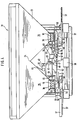
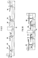
- the centrifugal spreader 1 designed as an add-on spreader spreader has the frame 2, which on its front side, viewed in the direction of travel 3, is equipped with the three-point coupling elements 4 for attachment to the tractor 5. Furthermore, the storage container 6 is fastened to the frame 2 and has two funnel-shaped container parts 8 separated by the roof-shaped central part 7. In the lower region of the funnel-shaped container parts 8, the setting elements 9 of the metering elements 10 are arranged and connected to the electronic setting device 11. The electronic setting device 11 delivers a value that is characteristic of the current application rate. This detected value is transmitted to an input unit 12 arranged on the tractor and provided with keys. This input unit 12 is designed as a microprocessor 13 and is coupled to the electronic setting device 11 via the cable 14.
- the application rate of the characteristic value detected by the electronic setting device is automatically compared with the target value specified and stored in the input and operating unit 12, so that the adjustment members 9 are adjusted when the actual value deviates from the predetermined target value, so that the respectively desired application rate is always kept constant.
- the centrifugal disks 16, each of which can be driven about an upright axis 15, are arranged below the metering elements 10.
- the centrifugal disks 16 are each equipped with the throwing elements 17 and are driven by the PTO shaft of the tractor 5 via the cardan shaft 18.
- the fertilizers located in the storage container 6 are fed to the centrifugal disks 16 in precisely adjustable amounts with the aid of the setting members 9 of the metering members 10.
- the fertilizer particles fed to the centrifugal disks 16 are picked up by the throwing elements 17 and thrown off over a certain spreading area, the individual, adjacent, overlapping spreading sectors of the individual spreading discs 16 being combined to form an entire spreading pattern.
- the regulation of the spreading quantity of the centrifugal spreader 1 is carried out depending on the driving speed of the tractor 5 carrying the centrifugal spreader 1.
- the driving speed is determined with the aid of a driving speed sensor 19 which is arranged on a non-driven wheel, for example the front wheel 20 of the tractor 5.
- This vehicle speed sensor 19 delivers characteristic values corresponding to the vehicle speed, which are passed on to the input and operating unit 12.
- the microprocessor 13 of the input and operating unit 12 uses these values, the so-called actual values, to carry out a comparison with the predetermined target values.
- a deviation from the specified target value, ie a deviation from the desired fertilizer application quantity per unit area leads to an automatic adjustment of the setting members 9 of the metering elements 10, so that the predetermined target value matches the actual value.
- the adjusting members arranged in the lower region of the funnel-shaped container parts 8 are each designed as a releasable base plate 21.
- the respective base plate 21 has the outlet openings 23 which can be adjusted with the slides 22 in different opening widths.
- the fertilizers trickling out of the opening cross-section of the outlet openings 23 released by the slides 22 reach the centrifugal disks 16 and are gripped by the respective throwing elements 17 and thrown off over a certain spreading area.
- the opening width of the outlet opening 23 is adjusted via the electronic adjusting device 11 connected to the slide 22.
- This electronic adjusting device 11 is arranged on the detachable base plate 21 and is designed as a spindle motor 24 which has the adjusting spindle 25.
- the adjustment or setting of the opening width of the respective outlet opening 23 takes place with the aid of the spindle motor 24.
- the spindle motor 24 is actuated by the input and operating unit 12 arranged on the tractor 5, which is connected to the electronic setting device 11 via the cable 26.
- a certain application rate per unit area can be preselected via the keyboard 27 arranged on the input and operating unit 12.
- the microprocessor 13 takes over the control of the electronic setting device 11 and adjusts the opening width in accordance with the predetermined application quantity value as a function of the driving speed by means of a corresponding slide actuation.
- a displacement transducer 28 which is arranged on the detachable base plate 21 with the aid of the fastening plate 29, is connected to the slide 22.
- the displacement sensor 28 determines the respective slide position of the slide 22 and supplies the value representing a certain application rate to the input and control unit 12, which is connected to the displacement sensor via the cable 30.
- the microprocessor 13 of the input and operating unit 12 compares the slide position of the slide 22 detected by the displacement sensor 28, which corresponds to a certain characteristic quantity output value with the predetermined target value and thus regulates the application quantity of the centrifugal spreader 1 as a function of the current driving speed of the tractor 5.
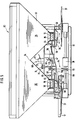
- the 4 is also designed as a centrifugal spreader 31 and has a frame 32, which is formed on its front side in the direction of travel with three-point coupling elements for attachment to the tractor 5.
- the storage container 33 is fastened to the frame 32 and has two funnel-shaped container parts 35 separated by the roof-shaped central part 34.
- the funnel-shaped container parts 35 each have the metering elements 10, which are designed as metering wheels 36, which close the container parts 35 downwards.
- the metering wheels 36 are designed as cam wheels.
- a distribution device designed as a centrifugal disc 37 is arranged below each of these metering elements 10.
- the centrifugal disks 37 are in the opposite direction of rotation via the gear 38 from the PTO shaft of the tractor carrying the attachment spreader driven.
- the metering device consisting of the metering wheels 36 is designed as a forced metering system.
- the metering wheels 36 arranged in the two funnel-shaped container parts 35 are driven by the controllable drive element 39, which is designed as an electric drive motor 40.
- the drive motor 40 is arranged under the roof-shaped middle part 34. Via the chain drive 41, the drive motor 40 drives the metering shaft 42 and the metering wheels 36.
- the metering shaft 42 is additionally mounted in the bearing housing 43 and has the couplings 44 which are connected via the cable 45 to the input and operating unit 12 arranged on the tractor.
- the actuation of the respective clutch 44 enables the metering wheels 36 to be stopped, so that the material supply to the respective centrifugal discs 37 can be interrupted separately and independently of one another, so that the effective spreading width is reduced.
- the speed of the metering wheels 36 is set according to the desired application rate per unit area via the input and operating unit 12.
- the drive motor 40 receives corresponding pulses via the cable 46, so that the drive motor 40 drives the metering wheels 36 at the correct speed.
- a speed monitoring device 47 is provided which interacts with the chain wheel 48 of the chain drive 41 and transmits corresponding pulses to the input and operating unit 12 and thus to the microprocessor 13 via the cable 49 of the respective speed.
- the material guiding element designed as a slide 50 is arranged displaceably.
- the adjusting device 51 is arranged on the slides 50.
- This adjusting device 51 has the adjusting lever 52 which are articulated to the slides 50 and are connected to one another via the rocker arm 53.
- the rocker arm 53 is fastened with the joint 54 to the roof-shaped central part 34.
- the adjusting levers 52 are coupled to the electric adjusting motor 55 and connected to the self-locking reduction gear 56, which has the adjusting spindle 57.
- the electric adjustment motor 55 is also fastened to the roof-shaped central part 34 and connected to the input and control unit 12 via the cable 58.
- the adjusting motor 55 receives pulses from the microprocessor 13 of the input and control unit 12, so that the chutes 50 are automatically adjusted depending on the application rate.
- the respective slide 50 is adjusted in the direction of arrow 59 and with larger application rates in the direction of arrow 60, so that the center of gravity of the material on the centrifugal disks 37 is closer to the outer edge of the centrifugal disc than with smaller application rates for larger application rates.
- the microprocessor 13 of the input and operating unit 12 is supplied with impulses about the distance traveled or about the actual, current driving speed from the driving speed sensor 19, which is arranged on the front wheel 20 of the tractor 5, the application rate is changed depending on the driving speed , so that the application rate per unit area remains constant at different driving speeds.
- the sensors 61 are arranged in the chutes 50 for detecting the actual current application rate. These sensors 61 are also connected to the input and control unit 12 via the cables 62.
- the microprocessor 13 of the input and control unit 12 is programmed in such a way that of the pulses determined by the sensors 61 about the actual application quantity, the slides 50 are adjusted via the adjusting device 51 connected to the microprocessor 13 such that the optimal feed focus of the material onto the centrifugal disks 37 is ensured depending on the size of the application quantity.
- the chutes 50 which determine the respective position of the center of gravity on the centrifugal discs 37, are automatically adjusted as a function of the application rate when the application rate changes.
- this centrifugal spreader 31 Using the respective adjustment devices and the respective monitoring devices arranged on this centrifugal spreader 31, it is possible, on the one hand, to keep the application rate of the centrifugal spreader 37 constant as a function of the respective driving speed. Furthermore, it is possible in a particularly simple manner to carry out a change in the application rate via the controllable drive member 39, so that the application rate can be adapted to the particular nutrient requirement of the area to be spread.
- the change in the application rate is entered into the input and control unit 12 of the microprocessor 13, whereby the adjustment and adjustment elements of the centrifugal spreader 31 are automatically adjusted so that the fertilizer is applied in accordance with the newly selected application rate value.
- the centrifugal spreader 31 is adjusted in such a way that the desired spread rate per unit area is again regulated as a function of the driving speed and kept constant.
- the centrifugal broadcaster 63 according to FIG. 5 differs from the centrifugal broadcaster 31 according to FIG. 1 in that the metering wheels 36 and the adjustment of the chutes 50 are driven differently.
- the metering wheels 36 are driven by the control gear designed as a variator gear 64.
- the drive pulley 65 of the variator gear 64 is fixed on the shaft 66 of the gear 38 and the output shaft 67 of the variator gear 64 on the drive shaft 68 of the metering wheels 36.
- the adjusting device 69 of the variator gear 64 is attached to the roof-shaped central part 34.
- the drive shaft 68 of the metering wheels 36 is still mounted in the bearing housing 70 fastened under the roof-shaped central part 34.
- the adjusting device 69 of the variator gear 64 has the electric adjusting motor 71, which is connected to the input and operating unit 12, with the self-locking reduction gear 72.
- the adjusting lever 73 with the joint 74 is also mounted on the roof-shaped central part 34.
- the adjusting lever 73 is connected on one side to the adjusting spindle 75 of the reduction gear 72 and on the other side it presses on the driven pulley 67 of the variator gear 64.
- the effective diameter of the variator gear 64 can be varied via the adjusting device 69, so that each corresponding speeds of the metering wheels 36 and thus the desired application rate can be set.
- the material guiding elements designed as slides 50 are also each displaceably arranged.
- the adjusting levers 76 are arranged on these slides 50 and are coupled to the adjusting lever 73 of the adjusting device 69 of the variator gear 64.
- the lever 77 is attached to the adjusting lever 73 and is connected in an articulated manner to the adjusting levers 76.
- the rocker arm 78 is also arranged as a transmission element, so that the slides 50 are also adjusted in opposite directions in accordance with the opposite direction of rotation of the centrifugal discs 37.
- the slides 50 of the centrifugal spreader 31 and 63 are arranged in a manner not shown, easily removable or pivoted away, so that the on their Drive shafts interchangeably arranged centrifugal disks 37 can be removed from their drive shafts and other centrifugal disks can be arranged on these drive shafts.
- the corresponding speed of the metering wheels 36 is set by the electric adjusting motor 71 of the adjusting device 69 via the variator gear 64 for the desired spread rate at the normal speed of the tractor PTO.
- the material metered by the metering wheels 36 from the storage container 33 is directed from the chutes 50 onto the centrifugal disks 37.
- the slides 50 determine the center of gravity of the material on the disks 37. Since the slides 50 are coupled to the adjustment mechanism 69 of the control gear 64, the slides 50 automatically change with each change in the speed of the metering wheels 36 via the variator gear 64 depending on the application rate the spread rate adjusted.
- the chutes 50 are adjusted in the direction of the arrow 60, i.e. in the direction of the outer edge of the centrifugal disk, while when the application rate is reduced in the direction of the arrow 59, i.e. in the direction of the axis of rotation of the centrifugal disk, they are adjusted.
- Couplings 44 assigned to a metering wheel 36 are arranged on the drive shaft 68 of the metering wheels 36 and are connected to the input and operating unit 12 via the cable 45. This makes it possible to interrupt the drive to the individual metering wheels 36 in such a way that no material is fed to the respective centrifugal disks 37, so that the effective spreading width changes.
- Speed monitoring device 47 on the drive shaft 68, which detects the drive speed of the metering wheels 36. This speed monitoring device 47 is connected via the cable 49 to the setting and operating unit 12 and supplies the respective speed corresponding characteristic pulses to the microprocessor 13 of the input and operating unit 12.
- the actual current application rate is recorded and transmitted to the microprocessor 13 via the cable 62.
- the desired application rate entered into the microprocessor 13 via the keyboard 27 can be regulated with the help of the microprocessor 13 such that the metering wheels 36 are driven in such a way that the amount of material fed to the centrifugal disks 37 corresponds to the actual current driving speed, so that the desired application rate per unit area entered in the microprocessor 13 is exactly adhered to.
- This desired spreading amount can be changed at any time during the spreading process by a corresponding actuation of the keyboard 27 of the input and operating unit 12, so that the fertilizer is supplied to the area to be sprinkled in accordance with the required nutrient requirements, so that an optimal nutrient supply to the soil can be achieved.
- the newly entered application rate value is always regulated depending on the driving speed, so that there is always a constant application rate corresponding to the respectively set application rate value.
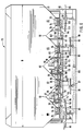
- the centrifugal spreader 79 according to FIG. 6 is also designed as a built-on centrifugal spreader and has the frame 80 and the reservoir 81. On its front side pointing in the direction of travel, this centrifugal spreader 79 is equipped with three-point coupling elements and can thus be connected to the three-point linkage of the tractor 5.
- the storage container 81 has a width B, which is the permissible dimension for the transport agricultural machinery on public roads and paths.
- the lower area of the storage container 81 is divided into four container tips 83 by three roof-shaped parts 82.
- Each container tip 83 has a metering device which is designed as metering wheels 84 and closes the container tips 83 downwards.
- centrifugal disks 85 are arranged as seen transversely to the direction of travel of the centrifugal spreader 79, with each container tip 83 being assigned a centrifugal disc 85. These centrifugal disks 85 are each equipped with two throwing blades 86. The centrifugal disks 85 are each driven in rotation about the upright axis 87 by the PTO shaft of the tractor 5 carrying the fertilizer spreader. The drive of the centrifugal disks 85, which are arranged at different heights, takes place via the gear transmission 88 from the tractor PTO shaft of the tractor 5.
- the arrangement of the centrifugal disks 85 is selected such that the two inner centrifugal disks, which are arranged at the same distance from the center of the machine, are deeper with respect to the outer centrifugal discs 85 are arranged.
- the gear mechanism 88 is designed such that the centrifugal disks 85 arranged on one side of the machine center are driven with the same direction of rotation. That is, an inner, lower centrifugal disc and an outer centrifugal disc 85 are driven with the same direction of rotation. However, the centrifugal disks 85 arranged on the right and left of the machine center are driven in opposite directions.
- the drive of the metering wheels 84 is designed such that the respective inner metering wheels 89 can be driven separately and independently of the outer metering wheels 90.
- the inner metering wheels 89 are driven by the controllable drive member 91, which is designed as an electric drive motor 92.
- the inner metering wheels 89 are mounted on the drive shaft 93 designed as a hollow shaft.
- the speed of the drive shaft 93 is determined with the aid of the speed monitoring device 94.
- the drive shaft 93 is driven by means of the chain drive 95.
- the two clutches 96 are arranged on the drive shaft 93, with the aid of which the drive to the respective inner metering wheels 89 can be interrupted as desired, so that the material supply to the respective inner centrifugal disks 85 is separated and can be interrupted independently.
- the respective outer metering wheels 90 are driven with the aid of the controllable drive element 97, which is also designed as an electric drive motor 98.
- the chain drive 99 is used to drive the drive shaft 100 on which the outer metering wheels 90 are fastened.
- the drive shaft 100 is also equipped with couplings 96 so that the drive to the respective outer metering wheels 90 can be interrupted independently of these metering wheels so that the material supply to the two outer centrifugal disks 85 can also be interrupted.
- the speed monitoring element 101 is arranged such that it delivers signals corresponding to the respective speed of this drive shaft 100 to the input and control unit 12, via which the element is connected to the cable 102.
- the material guiding element designed as a slide 103 is slidably arranged below the respective metering wheels 84.
- the individual slides 103 are connected to one another such that a simultaneous adjustment of the two inner slides 104 and the two outer slides 105 takes place independently of one another.
- the adjusting device 106 is assigned to the inner chutes 104 and the adjusting device 107 to the outer chutes 105.
- the adjusting device 106 has the adjusting lever 108, which is arranged on the slides 104 and via the rocker arm 109 are interconnected.
- the rocker arm 109 is fastened to the roof-shaped central part 82 with the joint 110.
- the electric adjusting motor 111 with the self-locking reduction gear 112, which has the adjusting spindle 113 is arranged on the adjusting levers 108.
- the electric adjustment motor 111 is fastened below the central roof-shaped part 82.
- the adjusting device 107 of the outer chutes 105 has the adjusting levers 114 which are arranged on the chutes 105 and are connected to one another via the rocker arm 115.
- the rocker arm 115 is fastened with the joint 116 to the left roof-shaped part 82.
- the electric adjusting motor 117 with the self-locking reduction gear 118, which has the adjusting spindle 119, is arranged on the adjusting lever 114.
- the electric adjustment motor 117 of the outer chutes 105 is fastened below the right roof-shaped central part.
- Both the lever arrangement by means of which the two inner chutes 104 and the two outer chutes 105 are connected to one another, is selected such that the respective chutes 104, 105 can also be adjusted in opposite directions in accordance with the opposite direction of rotation of the centrifugal discs 85.
- the sensors 120 are arranged in the respective chutes 103 in order to record the actual current application rate. These sensors 120 are connected to the microprocessor 13 of the input and control unit 12 via the cables 121. Appropriate programming of the microprocessor 13 results in an adjustment of the chutes 103 via the adjusting devices 106 and 107, which are likewise connected to the microprocessor, based on the pulses determined by the sensors 120 about the actual application rate, so that the optimum feed focus of the material is dependent on the size of the application rate on the Centrifugal disks 85 is guaranteed. Thus, the slides 103, which determine the position of the center of gravity on the centrifugal discs 85, are automatically adjusted as a function of the application rate when the application rate changes.
- controllable drive members 91 and 97, the speed monitoring devices 94 and 101, the clutches 96, the electric adjusting motors 111 and 117 of the respective adjusting devices 106 and 107 and the sensors 120 for detecting the actual current application rate each via corresponding cable connections to the microprocessor 13 are connected to the input and operating unit 12, the introduction and adjustment of the spreading quantity and the change of the effective spreading side can be carried out from the tractor. Since signals corresponding to the current driving speed are also transmitted to the microprocessor 13, the application rate is always adapted to the current driving speed, so that the desired application rate is kept constant as a function of the driving speed.
- a change in the effective spreading width can thus be carried out in the simplest way from the tractor, and a change in the spreading quantity can also be carried out from the tractor, so that the area to be sprinkled can be supplied with exactly the amount of fertilizer required for the particular nutrient requirement of the area to be sprinkled.
- the fertilizer spreader can be adapted exactly to the required conditions of use.
- the farmer can change the fertilizer application rate in accordance with an existing nutrient profile of the area to be spread in a simple manner, so that the area to be spread is exactly that required to cover the area required Nutrients required fertilizers are supplied.
- This means that fertilizers can be applied specifically to the nutrient requirements of the area to be spread.
- This change in the fertilizer application rate in accordance with the required nutrient requirement of the area to be spread can be carried out both manually and automatically by the microprocessor.
- the microprocessor 13 of the input and operating unit takes over the adjustment of the respective setting elements of the metering elements in accordance with a nutrient profile of the area to be sprinkled stored in the microprocessor 13.
- the microprocessor 13 determines the amount of fertilizer required for optimum nutrient supply, and adjusts the setting elements of the metering elements based on the determined nutrient requirement, so that the area to be sprinkled is supplied with exactly the amount of fertilizer required to cover the optimal nutrient supply.
- the centrifugal fertilizer spreader according to FIG. 7 is also designed as a centrifugal spreader 122 and has the frame 123 and the reservoir 124.
- This centrifugal spreader 122 has the known and not shown three-point coupling elements on its front side pointing in the direction of travel, via which it can be connected in a known manner to the three-point linkage of the tractor.
- the lower region of the storage container 124 is divided into four container tips 126 by three roof-shaped parts 125.
- Each Container tip 126 has a flat base plate 127, to which the removable base plate 128, in which the outlet openings 129 are located, is fastened.
- a metering element designed as a slide 130, with which the opening width of the respective outlet opening 129 can be adjusted or closed.
- the slides 130 can be operated independently of one another via the input and operating unit 12 from the tractor.
- Each slide 130 is actuated via an electric servomotor 131, which is equipped with an adjusting spindle 132 and is fastened on the base plate 128.
- the adjusting spindle 132 is connected in an articulated manner to the adjusting lever 133 of the slide 130.
- An electronic recess 134 interacts with the adjusting lever 133 and serves to determine the respective slide position of the slide 130 pivotably mounted about the bolt 135.
- the electric servomotor 131 and the electronic pickup 134 are connected to the input and operating unit 12 of the microprocessor 13 via the cables 136 and 137.
- the horizontally running and drivable agitator shaft 138 which is mounted and sealed in the walls of the container tips 126.
- the stirring shaft 138 projects into all the container tips 126 and has the stirring pins 139 in the interior of the storage container 124, in the region of the container tips 126.
- centrifugal disks 140 and 141 are arranged next to one another, as seen transversely to the direction of travel of the centrifugal spreader, and are each equipped with two throwing blades 142.
- the centrifugal discs 140, 141 are each driven about the upright axis 143 by the PTO of the tractor 5 carrying the fertilizer spreader.
- the centrifugal disks 140, 141 are arranged at different heights from one another.
- the two inner ones, a little deeper arranged centrifugal disks 140, which are arranged at the same distance from the center of the machine, are driven by the tractor PTO via the gear transmission 144, so that the centrifugal disks 140 rotate about their upright axis 143.
- the outer centrifugal discs 141 which are arranged somewhat higher in relation to the inner centrifugal discs 140, are driven by the shafts 146 of the inner centrifugal discs 140 via the V-belt drives 145 and set in rotation.
- the gear transmission 144 continues to drive the agitator shaft 138 via the chain drive 147.
- the centrifugal disks 140, 141 are arranged on the shafts 143 in an easily detachable manner, so that they can be easily replaced with other or differently designed centrifugal disks if necessary.
- the throwing blades 142 placed on the centrifugal disks 140 and 141 are arranged at an angle to one another with respect to the respectively adjacent centrifugal disk.
- the rotatingly driven centrifugal disks 140, 141 are fed with the help of the slide 130 the fertilizer particles to be applied in precisely adjustable amounts. These fertilizer particles are thrown off by the throwing blades 142 arranged on the rotating centrifugal disks 140, 141 and distributed evenly on the ground surface.
- the desired application rate can be set and adjusted using the setting and operating unit 12 which is arranged on the tractor 5.
- the microprocessor 13 of the input and control unit 12 takes over the automatic regulation of the application rate depending on the current driving speed, so that the desired application rate per unit area is kept constant.
- the actual application rate is detected with the aid of the sensors 148 arranged below the outlet openings 129 and passed on to the microprocessor 13, to which the sensors are connected via the cables 149.
- the sensors 148 detect the current one
- the application rate of the respective outlet openings 129 independently of one another and deliver characteristic signals corresponding to the current application rate, which signals are transmitted to the microprocessor 13 and processed here.
- This microprocessor 13 processes the signals supplied to it in such a way that the application rate is regulated as a function of the current driving speed.
- the spreading quantity can be changed as desired using the setting and operating unit 12 during the spreading process, the spreading quantity always being regulated taking into account the respectively set target value as a function of the driving speed.
- the materials to be dispensed can also be supplied to the respective centrifugal disks 140, 141 in different amounts, as a result of which different, desired, application rates can be applied within the effective spreading width of the centrifugal spreader 122. That is, the individual centrifugal disks 140, 141 can be supplied with different amounts of fertilizer, which means that they are adapted to the individual nutrient requirements of the area sprinkled by the respective centrifugal disk, so that the area to be sprinkled is supplied with exactly the amounts of fertilizer necessary for optimal nutrient supply.
- the spread rate set on the individual centrifugal disks is always controlled as a function of the current driving speed, so that the spread rate is constant within a spreading range of each centrifugal disk.
- centrifugal disks 140, 141 In addition to arranging the centrifugal disks 140, 141 at different heights, a mutual obstruction of the fertilizer particles thrown off by the throwing vanes 142 of the respective centrifugal disks is to be prevented by the throwing vanes 142 on the in each case adjacent centrifugal discs are arranged at an angle to one another. This ensures that the individual fertilizer particles do not interfere with each other on their trajectories.
- the storage container 124 with its centrifugal disks 140, 141 arranged below its container within the area laterally delimited by the container 124 has a width B which is less than or equal to 3 m both in the operating position and in the transport position.
- FIG. 9 shows a further possibility of the centrifugal disc arrangement and the drive for these centrifugal discs.
- the two inner, approximately lower arranged centrifugal disks 150 are arranged at the same distance from the center of the machine, and are driven by the tractor PTO via the gear mechanism 151, so that the centrifugal disks 150 rotate about their upright axis 152.
- the throwing blades 153 are attached to the centrifugal discs 150 in such a way that the fertilizers are thrown horizontally from the centrifugal discs 150.
- the outer centrifugal discs 154 which are arranged somewhat higher in relation to the inner centrifugal discs 150, are likewise driven via the gear mechanism 151 and are set in rotation.
- the centrifugal disks 154 are designed such that the throwing blades 155 arranged on these centrifugal disks 154 raise the fertilizers when they are spun off, so that the trajectories of the fertilizer particles thrown off by the individual centrifugal disks 150, 154 do not interfere with one another, which is due to the angularly offset arrangement of the throwing vanes 153 , 155 on the respective adjacent centrifugal disks 150, 154, should continue to be prevented.
- the drive of the centrifugal discs, which are arranged on one side of the machine center takes place in the same Direction of rotation, whereby the centrifugal disks arranged on the right and left of the machine center are driven in the opposite direction of rotation.
- the centrifugal disc arrangement shows a further possibility of the centrifugal disc arrangement, the individual centrifugal discs being driven via the gear transmission 156.
- the two inner centrifugal disks 157 are arranged at the same distance from the center of the machine and rotate about the upright axis 158.
- the outer centrifugal disks 159 which are somewhat higher in relation to the inner centrifugal disks 157, are in some cases located exactly above the centrifugal disks 157 and become about the upright axis 160 driven.
- the adjacent centrifugal disks 157, 159 are each driven in opposite rotation.
- the throwing vanes 161 arranged on the respective centrifugal disks are also arranged at an angular offset.
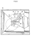
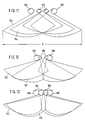
- 11 to 15 show the different arrangement of centrifugal disks and the individual spreading fans produced by these centrifugal disks in a basic illustration.
- 11 shows the arrangement of four centrifugal disks 162 and 163.
- the two inner centrifugal disks 162 are arranged somewhat lower in relation to the outer centrifugal disks 163.
- the centrifugal discs are driven in the direction of the arrow shown and each generate a spreading fan in the manner shown, and can be combined to form an entire spread pattern.
- the effective spreading width S results from the individual, overlapping individual spreading compartments 164 arranged next to one another.
- the effective spreading width S can be combined as desired by sub-calculating the fertilizer feed to the individual centrifugal discs.
- the centrifugal discs 165 and 166 show a different arrangement of the centrifugal discs 165 and 166.
- the inner centrifugal discs 165 are arranged at the same distance from the center of the machine and are partially located below the somewhat higher centrifugal discs 166.
- the individual centrifugal discs 165 and 166 are in the direction of the arrow shown driven and each produce the individual spreading fans 167 in the manner shown, which, when put together, form the overall spreading pattern.
- FIG. 13 shows a further possibility of arranging the centrifugal discs 168 and 169.
- the centrifugal discs 168 which are arranged somewhat lower are arranged such that they are partially below the centrifugal discs 169 which are arranged somewhat higher.
- the individual centrifugal disks are driven in the direction of the arrow shown in each case and produce the individual spreading fans 170 which are assembled to form the spreading fan extending over the entire spreading width.
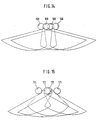
- FIG. 14 shows an arrangement of the centrifugal discs which corresponds to the arrangement of the centrifugal discs according to FIG. 13.
- the only difference compared to the centrifugal discs according to FIG. 13 is the drive direction of the individual centrifugal discs.
- the individual centrifugal discs are driven in the direction of the arrow.
- a change in the drive direction of the respective centrifugal disks leads to a change in the spreading compartments produced by the individual centrifugal discs, which also changes the manner in which the individual spreading compartments arranged next to one another overlap.
- centrifugal disks 171, 172 are again arranged at different heights, the central centrifugal disks 172 being located one below the other and, for example, producing the individual, shown spreading fans, which can be combined to form the overall spread pattern.
- the individual centrifugal disks 171, 172 are driven in the direction of the arrow shown.
Landscapes
- Life Sciences & Earth Sciences (AREA)
- Soil Sciences (AREA)
- Environmental Sciences (AREA)
- Fertilizing (AREA)
- Fertilizers (AREA)
- Sowing (AREA)
- Circuits Of Receivers In General (AREA)
- Soil Conditioners And Soil-Stabilizing Materials (AREA)
- Extrusion Moulding Of Plastics Or The Like (AREA)
Claims (3)
- Procédé de mise en oeuvre d'un distributeur centrifuge comprenant un réservoir d'alimentation (6) équipé dans sa partie inférieure, d'organes de dosage (10) fournissant suivant des quantités réglables, le produit du réservoir d'alimentation (62) à plusieurs disques d'épandage (16) entraînés en rotation et équipés d'éléments d'éjection, le réservoir d'alimentation (6) se composant d'au moins deux réservoirs séparés pour des types d'engrais différents, auxquels sont associés chaque fois des organes de dosage pour que les types d'engrais différents ruisselant des réservoirs d'alimentation soient fournis respectivement à un disque d'épandage, les organes de dosage (10) étant réalisés sous la forme d'orifices de sortie (23, 129) dont le degré d'ouverture se règle respectivement à l'aide de tiroirs (22, 130), procédé caractérisé en ce qu'un dispositif de réglage électronique (11, 12, 24, 28, 134) est relié aux tiroirs (22, 130), le dispositif de réglage (11, 12, 24, 28, 131, 134) détectant la valeur caractéristique de la quantité instantanée distribuée, en ce que le dispositif de réglage électronique (11, 12, 24, 28, 131, 134) détecte la position respective des tiroirs et enregistre dans le dispositif de réglage électronique (11, 12, 24, 28, 131, 134) pour chaque position respective du tiroir, la quantité correspondante d'engrais et en ce qu'à partir des valeurs caractéristiques des quantités à distribuer, il règle automatiquement une valeur de consigne prédéterminée, le dispositif de réglage électronique (12) tenant compte de l'alimentation existant en amendement du champ à traiter, et en fonction de l'alimentation nécessaire en amendement pour la surface à traiter, il commande les organes de dosage et en ce que la quantité distribuée fournie à chaque disque d'épandage se règle indépendamment des autres.
- Procédé selon la revendications 1, caractérisé en ce qu'au niveau des organes de dosage (10, 36, 84) se trouvent des capteurs (61, 12, 148) pour déterminer la quantité réelle instantanée à distribuer et en ce que ces capteurs sont reliés au dispositif de réglage électronique (11, 12, 24, 28, 39, 40, 47, 91, 92, 94, 97, 98, 101, 131, 13).
- Procédé selon la revendication 1, caractérisé en ce qu'à chaque tiroir (22, 130) d'un disque d'épandage, est associé un moteur de réglage (39, 131) électrique, indépendant qui est relié au dispositif de réglage électronique (12).
Applications Claiming Priority (3)
| Application Number | Priority Date | Filing Date | Title |
|---|---|---|---|
| DE3617302 | 1986-05-23 | ||
| DE19863617302 DE3617302A1 (de) | 1986-05-23 | 1986-05-23 | Schleuderstreuer mit vorratsbehaelter |
| EP87107098A EP0246575B1 (fr) | 1986-05-23 | 1987-05-15 | Distributeur à disques avec trémie |
Related Parent Applications (1)
| Application Number | Title | Priority Date | Filing Date |
|---|---|---|---|
| EP87107098.3 Division | 1987-05-15 |
Publications (3)
| Publication Number | Publication Date |
|---|---|
| EP0443634A2 EP0443634A2 (fr) | 1991-08-28 |
| EP0443634A3 EP0443634A3 (en) | 1991-10-30 |
| EP0443634B1 true EP0443634B1 (fr) | 1994-10-05 |
Family
ID=6301429
Family Applications (3)
| Application Number | Title | Priority Date | Filing Date |
|---|---|---|---|
| EP91105418A Expired - Lifetime EP0443634B1 (fr) | 1986-05-23 | 1987-05-15 | Distributeur d'engrais centrifuge avec trémie |
| EP87107098A Expired - Lifetime EP0246575B1 (fr) | 1986-05-23 | 1987-05-15 | Distributeur à disques avec trémie |
| EP91105419A Revoked EP0445842B1 (fr) | 1986-05-23 | 1987-05-15 | Distributeur d'engrais centrifuge avec trémie |
Family Applications After (2)
| Application Number | Title | Priority Date | Filing Date |
|---|---|---|---|
| EP87107098A Expired - Lifetime EP0246575B1 (fr) | 1986-05-23 | 1987-05-15 | Distributeur à disques avec trémie |
| EP91105419A Revoked EP0445842B1 (fr) | 1986-05-23 | 1987-05-15 | Distributeur d'engrais centrifuge avec trémie |
Country Status (3)
| Country | Link |
|---|---|
| EP (3) | EP0443634B1 (fr) |
| AT (3) | ATE109613T1 (fr) |
| DE (4) | DE3617302A1 (fr) |
Families Citing this family (27)
| Publication number | Priority date | Publication date | Assignee | Title |
|---|---|---|---|---|
| NL8901903A (nl) * | 1989-07-24 | 1991-02-18 | Lely Nv C Van Der | Machine voor het verspreiden van materiaal. |
| DE4012395A1 (de) * | 1990-04-19 | 1991-10-24 | Amazonen Werke Dreyer H | Verfahren zur steuerung landwirtschaftlicher verteilmaschinen |
| DE4016603A1 (de) * | 1990-05-23 | 1991-11-28 | Amazonen Werke Dreyer H | Bordcomputersystem fuer landwirtschaftliche maschinen- und geraetekombinationen |
| DE4102783A1 (de) * | 1991-01-31 | 1992-08-06 | Amazonen Werke Dreyer H | Schleuderduengerstreuer |
| SE9403575L (sv) | 1994-10-19 | 1996-04-20 | Ericsson Telefon Ab L M | Benram för kapslad optokomponent |
| DE19511305A1 (de) * | 1995-03-28 | 1996-10-02 | Dieter Herold | Verfahren und Vorrichtung zum Einwirken auf landwirtschaftliche Nutzflächen |
| NL1004118C1 (nl) * | 1996-09-10 | 1998-03-11 | Maasland Nv | Inrichting voor het verspreiden van korrel- en/of poedervormig materiaal. |
| CZ101198A3 (cs) * | 1997-04-10 | 1998-11-11 | Amazonen-Werke H. Dreyer Gmbh & Co. Kg | Odstředivé rozmetadlo hnojiva |
| EP0870423A1 (fr) | 1997-04-10 | 1998-10-14 | Amazonen-Werke H. Dreyer GmbH & Co. KG | Méthode pour déposer un seul fertilisant, ou bien plusieurs en même temps, avec un épandeur d'engrais |
| DE19832227C2 (de) * | 1997-08-06 | 2003-08-28 | Rauch Landmaschfab Gmbh | Schleuderstreuer |
| DE19735525A1 (de) * | 1997-08-16 | 1999-02-18 | Amazonen Werke Dreyer H | Verfahren zum Einsatz eines Zentrifugalstreuers |
| DE19742440A1 (de) * | 1997-09-26 | 1999-04-01 | Amazonen Werke Dreyer H | Schleuderstreuer |
| EP0910939A1 (fr) * | 1997-10-15 | 1999-04-28 | Amazonen-Werke H. Dreyer GmbH & Co. KG | Epandeur centrifuge |
| DE19929356C2 (de) * | 1998-07-09 | 2003-10-09 | Rauch Landmaschfab Gmbh | Schleuderstreuer |
| DK0981939T3 (da) * | 1998-08-26 | 2003-09-29 | Laursen As A P | Fremgangsmåde til spredning af strømbart materiale |
| DE19958451A1 (de) * | 1999-12-03 | 2001-06-07 | Amazonen Werke Dreyer H | Schleuderdüngerstreuer |
| NL1016944C2 (nl) * | 2000-12-21 | 2002-06-25 | Lely Entpr Ag | Inrichting voor het verspreiden van korrel- en/of poedervormig materiaal. |
| WO2006072248A1 (fr) † | 2005-01-07 | 2006-07-13 | Hardi International A/S | Procede et systeme de reglage de la pression |
| DE102007051713A1 (de) | 2007-10-30 | 2009-05-07 | Rauch Landmaschinenfabrik Gmbh | Zweischeibenstreuer zum Verteilen von Mineraldünger |
| EP2915419B1 (fr) * | 2014-03-06 | 2016-09-21 | O.M.S.M.A.G. S.n.c. | Dispositif polyvalent agricol |
| CN104206085A (zh) * | 2014-09-03 | 2014-12-17 | 安徽久力机械设备有限公司 | 一种农业施肥机 |
| DE102015011949A1 (de) | 2015-09-18 | 2017-03-23 | Rauch Landmaschinenfabrik Gmbh | Verteilmaschine mit wenigstens zwei Verteilerscheiben mit variabler Drehzahl |
| CN105766108A (zh) * | 2016-03-15 | 2016-07-20 | 万庆昆 | 施肥装置 |
| CN105993339B (zh) * | 2016-07-19 | 2018-08-03 | 宁夏智源农业装备有限公司 | 林果有机肥撒肥机 |
| DE202017001237U1 (de) * | 2017-03-09 | 2018-03-12 | Rauch Landmaschinenfabrik Gmbh | Verteilmaschine und hierfür geeignetes Dosierorgan |
| CN110291876A (zh) * | 2019-06-26 | 2019-10-01 | 徐州市贾汪区贾汪镇宏发水蜜桃营销专业合作社 | 一种水蜜桃种植的施肥装置 |
| MY193207A (en) * | 2020-11-27 | 2022-09-26 | Sime Darby Plantation Intellectual Property Sdn Bhd | Fertiliser device |
Family Cites Families (12)
| Publication number | Priority date | Publication date | Assignee | Title |
|---|---|---|---|---|
| BE755901A (nl) * | 1969-09-12 | 1971-02-15 | Lely Nv C Van Der | Inrichting voor het verspreiden van strooibaar materiaal |
| DE2439046C2 (de) * | 1974-08-14 | 1984-04-05 | Robert Bosch Gmbh, 7000 Stuttgart | Einrichtung zum Verteilen von Streugut |
| AU497267B2 (en) * | 1975-09-09 | 1978-12-07 | Dickey-John Corporation | Calibrated seed planting monitor |
| NL187607C (nl) * | 1977-05-09 | 1991-12-02 | Lely Nv C Van Der | Inrichting voor het over of in de grond verspreiden van korrel- en/of poedervormig materiaal. |
| DK152578A (da) * | 1978-04-06 | 1979-10-07 | Nordsten P | Apparat til lukning af saaskodder i en saamaskine |
| GB1600407A (en) * | 1978-05-30 | 1981-10-14 | Teagle W T | Machines for broadcasting seed fertilizer and other granular or powdered materials |
| NL8105285A (nl) * | 1981-11-23 | 1983-06-16 | Lely Nv C Van Der | Inrichting voor het verspreiden van korrel- en/of poedervormig materiaal. |
| DE3377195D1 (en) * | 1982-01-21 | 1988-08-04 | Kuhn Sa | Manure spreader |
| NL8200958A (nl) * | 1982-03-09 | 1983-10-03 | Lely Nv C Van Der | Inrichting voor het verspreiden van korrel- en/of poedervormig materiaal. |
| ATE127656T1 (de) * | 1983-06-03 | 1995-09-15 | Lely Nv C Van Der | Streuen von material auf eine oberfläche. |
| DE3337762C2 (de) | 1983-10-18 | 1987-01-02 | Amazonen-Werke H. Dreyer Gmbh & Co Kg, 4507 Hasbergen | Schleuderstreuer |
| NZ214073A (en) * | 1984-11-06 | 1987-07-31 | Soil Teq Inc | Fertiliser blender and spreader: blend controlled by current soil type |
-
1986
- 1986-05-23 DE DE19863617302 patent/DE3617302A1/de not_active Withdrawn
-
1987
- 1987-05-15 AT AT91105419T patent/ATE109613T1/de not_active IP Right Cessation
- 1987-05-15 EP EP91105418A patent/EP0443634B1/fr not_active Expired - Lifetime
- 1987-05-15 DE DE3750376T patent/DE3750376D1/de not_active Revoked
- 1987-05-15 AT AT91105418T patent/ATE112443T1/de not_active IP Right Cessation
- 1987-05-15 EP EP87107098A patent/EP0246575B1/fr not_active Expired - Lifetime
- 1987-05-15 AT AT87107098T patent/ATE72919T1/de not_active IP Right Cessation
- 1987-05-15 EP EP91105419A patent/EP0445842B1/fr not_active Revoked
- 1987-05-15 DE DE3750637T patent/DE3750637D1/de not_active Expired - Fee Related
- 1987-05-15 DE DE8787107098T patent/DE3776963D1/de not_active Expired - Lifetime
Also Published As
| Publication number | Publication date |
|---|---|
| ATE112443T1 (de) | 1994-10-15 |
| EP0445842B1 (fr) | 1994-08-10 |
| EP0443634A3 (en) | 1991-10-30 |
| DE3750637D1 (de) | 1994-11-10 |
| DE3617302A1 (de) | 1987-11-26 |
| EP0246575A2 (fr) | 1987-11-25 |
| DE3776963D1 (de) | 1992-04-09 |
| ATE109613T1 (de) | 1994-08-15 |
| EP0246575A3 (en) | 1989-06-14 |
| ATE72919T1 (de) | 1992-03-15 |
| EP0443634A2 (fr) | 1991-08-28 |
| DE3750376D1 (de) | 1994-09-15 |
| EP0246575B1 (fr) | 1992-03-04 |
| EP0445842A1 (fr) | 1991-09-11 |
Similar Documents
| Publication | Publication Date | Title |
|---|---|---|
| EP0443634B1 (fr) | Distributeur d'engrais centrifuge avec trémie | |
| EP3338524B1 (fr) | Semoir monograine agricole et procédé | |
| EP0330839B1 (fr) | Epandeur centrifuge | |
| DE4223585A1 (de) | Vorrichtung zum Ausbringen von landwirtschaftlichem Material | |
| EP0540889B2 (fr) | Epandeur d'engrais centrifuge | |
| EP0820219B1 (fr) | Epandeur d'engrais centrifuge | |
| EP0545894B2 (fr) | Epandeur centrifuge | |
| DE102007038510B4 (de) | Vorrichtung zum Dosieren und Verteilen von landwirtschaftlichen und kommunalen Schüttgütern | |
| EP0222337B1 (fr) | Distributeur à disques, spécialement pour engrais granulés | |
| DE4134315A1 (de) | Schleuderduengerstreuer | |
| EP0427936B1 (fr) | Epandeur d'engrais centrifuge | |
| EP0559242B1 (fr) | Expandeur centrifuge | |
| EP0278251B1 (fr) | Epandeur à disques centrifuges | |
| EP0988780A2 (fr) | Procédé pour l'épandage au long de bords ou limites | |
| DE4016595C2 (de) | Verteilmaschine | |
| EP0392257B1 (fr) | Méthode de distribution d'engrais avec un épandeur centrifuge | |
| EP0870423A1 (fr) | Méthode pour déposer un seul fertilisant, ou bien plusieurs en même temps, avec un épandeur d'engrais | |
| DE102020100394A1 (de) | Landwirtschaftliche Verteilmaschine | |
| EP0379103A1 (fr) | Epandeur centrifuge | |
| DD297905A5 (de) | Schleuderduengerstreuer | |
| DE2425408C2 (de) | Maschine zum Ausbringen von Saatgut und streufähigen Düngemitteln | |
| DE3608935A1 (de) | Schleuderstreuer | |
| DE19742441A1 (de) | Schleuderstreuer | |
| DE19717285A1 (de) | Schleuderdüngerstreuer | |
| EP4026417A1 (fr) | Procédé d'épandage d'un produit d'épandage |
Legal Events
| Date | Code | Title | Description |
|---|---|---|---|
| PUAI | Public reference made under article 153(3) epc to a published international application that has entered the european phase |
Free format text: ORIGINAL CODE: 0009012 |
|
| 17P | Request for examination filed |
Effective date: 19910405 |
|
| AC | Divisional application: reference to earlier application |
Ref document number: 246575 Country of ref document: EP |
|
| AK | Designated contracting states |
Kind code of ref document: A2 Designated state(s): AT DE FR GB NL SE |
|
| PUAL | Search report despatched |
Free format text: ORIGINAL CODE: 0009013 |
|
| AK | Designated contracting states |
Kind code of ref document: A3 Designated state(s): AT DE FR GB NL SE |
|
| 17Q | First examination report despatched |
Effective date: 19921028 |
|
| GRAA | (expected) grant |
Free format text: ORIGINAL CODE: 0009210 |
|
| AC | Divisional application: reference to earlier application |
Ref document number: 246575 Country of ref document: EP |
|
| AK | Designated contracting states |
Kind code of ref document: B1 Designated state(s): AT DE FR GB NL SE |
|
| PG25 | Lapsed in a contracting state [announced via postgrant information from national office to epo] |
Ref country code: GB Effective date: 19941005 Ref country code: FR Effective date: 19941005 |
|
| REF | Corresponds to: |
Ref document number: 112443 Country of ref document: AT Date of ref document: 19941015 Kind code of ref document: T |
|
| REF | Corresponds to: |
Ref document number: 3750637 Country of ref document: DE Date of ref document: 19941110 |
|
| PG25 | Lapsed in a contracting state [announced via postgrant information from national office to epo] |
Ref country code: SE Effective date: 19950105 |
|
| EN | Fr: translation not filed | ||
| GBV | Gb: ep patent (uk) treated as always having been void in accordance with gb section 77(7)/1977 [no translation filed] |
Effective date: 19941005 |
|
| PG25 | Lapsed in a contracting state [announced via postgrant information from national office to epo] |
Ref country code: AT Effective date: 19950515 |
|
| PLBE | No opposition filed within time limit |
Free format text: ORIGINAL CODE: 0009261 |
|
| STAA | Information on the status of an ep patent application or granted ep patent |
Free format text: STATUS: NO OPPOSITION FILED WITHIN TIME LIMIT |
|
| 26N | No opposition filed | ||
| PGFP | Annual fee paid to national office [announced via postgrant information from national office to epo] |
Ref country code: NL Payment date: 20020531 Year of fee payment: 16 |
|
| PG25 | Lapsed in a contracting state [announced via postgrant information from national office to epo] |
Ref country code: NL Free format text: LAPSE BECAUSE OF NON-PAYMENT OF DUE FEES Effective date: 20031201 |
|
| NLV4 | Nl: lapsed or anulled due to non-payment of the annual fee |
Effective date: 20031201 |
|
| PGFP | Annual fee paid to national office [announced via postgrant information from national office to epo] |
Ref country code: DE Payment date: 20050531 Year of fee payment: 19 |
|
| PG25 | Lapsed in a contracting state [announced via postgrant information from national office to epo] |
Ref country code: DE Free format text: LAPSE BECAUSE OF NON-PAYMENT OF DUE FEES Effective date: 20061201 |