EP0443679A1 - Kodierverfahren gemäss der RSA-Methode durch einen Mikrokontroller und einen Apparat, die dieses Verfahren benutzen - Google Patents
Kodierverfahren gemäss der RSA-Methode durch einen Mikrokontroller und einen Apparat, die dieses Verfahren benutzen Download PDFInfo
- Publication number
- EP0443679A1 EP0443679A1 EP91200332A EP91200332A EP0443679A1 EP 0443679 A1 EP0443679 A1 EP 0443679A1 EP 91200332 A EP91200332 A EP 91200332A EP 91200332 A EP91200332 A EP 91200332A EP 0443679 A1 EP0443679 A1 EP 0443679A1
- Authority
- EP
- European Patent Office
- Prior art keywords
- bits
- variable
- value
- modulo
- calculation
- Prior art date
- Legal status (The legal status is an assumption and is not a legal conclusion. Google has not performed a legal analysis and makes no representation as to the accuracy of the status listed.)
- Granted
Links
Images


Classifications
-
- G—PHYSICS
- G06—COMPUTING OR CALCULATING; COUNTING
- G06F—ELECTRIC DIGITAL DATA PROCESSING
- G06F7/00—Methods or arrangements for processing data by operating upon the order or content of the data handled
- G06F7/60—Methods or arrangements for performing computations using a digital non-denominational number representation, i.e. number representation without radix; Computing devices using combinations of denominational and non-denominational quantity representations, e.g. using difunction pulse trains, STEELE computers, phase computers
- G06F7/72—Methods or arrangements for performing computations using a digital non-denominational number representation, i.e. number representation without radix; Computing devices using combinations of denominational and non-denominational quantity representations, e.g. using difunction pulse trains, STEELE computers, phase computers using residue arithmetic
- G06F7/723—Modular exponentiation
-
- G—PHYSICS
- G06—COMPUTING OR CALCULATING; COUNTING
- G06F—ELECTRIC DIGITAL DATA PROCESSING
- G06F7/00—Methods or arrangements for processing data by operating upon the order or content of the data handled
- G06F7/60—Methods or arrangements for performing computations using a digital non-denominational number representation, i.e. number representation without radix; Computing devices using combinations of denominational and non-denominational quantity representations, e.g. using difunction pulse trains, STEELE computers, phase computers
- G06F7/72—Methods or arrangements for performing computations using a digital non-denominational number representation, i.e. number representation without radix; Computing devices using combinations of denominational and non-denominational quantity representations, e.g. using difunction pulse trains, STEELE computers, phase computers using residue arithmetic
- G06F7/722—Modular multiplication
Definitions
- the present invention also relates to a device implementing such a method.
- the technological limitations of current devices include the low memory capacity (a few hundred bytes), the limited clock speed (of the order of 8 MHz only) and the low number of bits processed in parallel (8 or 16 bits only).
- the processing algorithm avoids having to perform calculations on large numbers and uses for this purpose a fractionation of the calculation variables and a modulo N reduction after each partial multiplication, so as to avoid an increase in the length of these variables as the treatment is continued sequentially.
- the slowing down of processing due to the test operations in question is all the more significant since it must occur a very large number of times during the calculation of exponentiation modulo N, and when the operating cycle time of the central unit is comparatively slow compared to the operating cycle time of the calculation cell, typically in a ratio of 8 to 1.
- the object of the invention is therefore to propose a method allowing the execution of a coding by the RSA method by means of a microcontroller provided with a specialized calculation cell, which is faster than the method. known, in particular by the fact that tests of sign or of magnitude of calculation variables, would be made much less frequent.
- the reduction in length of the variable B i can in no case provide a result of negative sign and it is therefore no longer necessary to test this sign. Processing can therefore be carried out systematically and without interruption, at least during a certain number of successive operations beyond which there is a risk that the accumulation of the overflow can no longer be taken into account in the p format. bits of the quotient q.
- the predetermined number of operations executed successively while leaving the exceeding of the variable A i the possibility of increasing is advantageously chosen equal to the number of multiplications a i .X followed by their quasi-reductions modulo N, which are necessary to exhaust the variable A using its successive extracts a i .
- This number corresponds to the upper integer of the n / m ratio.
- the value of the approximate quotient q, having the desired degree of precision, can be determined, according to the invention, in several ways.
- a first embodiment of the invention in which the value of the module N is taken in a particular interval, is characterized in that said particular interval is equal to: 2n - 2 (nm) at 2 not - 1 and in that the value of the approximate quotient q is provided by the most significant bits of the variable B i which exceed the n-bit format.
- the value of the approximate quotient q is found immediately and can be recycled in the specialized processing unit, as an operand for modulo N reduction without even passing through a data memory.
- the corresponding memory location can therefore be saved.
- bits are multiples of 8, and are well suited to a microcontroller working by 8-bit words with which is associated a calculation cell also working on 8-bit operands.
- the value of p-m is equal to 8 bits (that is to say a byte) making it possible to receive the cumulation of overflow consecutive to a reduction modulo N possibly incomplete until an additional reduction is carried out.
- the method according to the invention also applies when the value of the module N is chosen in any way from among the numbers with n bits.
- the value N * can be precalculated in advance and supplied to the microcontroller as data in the same way as N or N '.
- the value of the approximate quotient q is determined following a small additional operation (multiplication of two numbers, one of 4 bytes and the other of 7 bytes), which is of the same type as the reduction operation modulo N but much shorter since the multiplicand is only 7 bytes.
- the invention also relates to a device provided with a central microcomputer unit controlled by a program characterized in that the said program implements the method defined above.
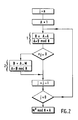
- the RSA coding method consists in carrying out the exponentiation by a modulo number N of a message M; N, e and M being whole numbers of great length included in a format with n bits, n being able to be of the order of 512 bits.
- a first effect of the modulo N function is that the result is reduced to a format which does not exceed n bits.
- Another property of the modulo N function is that one can choose when to apply the modulo N reduction without compromising the accuracy of the final result, which has the advantage of reducing the length of the calculation variable before that it does not reach a prohibitive length for a microcontroller whose computation capacity and the quantity of memories are very limited.
- Figure 2 shows how the algorithm of Figure 1 can be modified to obtain the exponentiation by a number e, modulo N, of a message M.
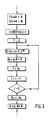
- FIG. 3 shows a more detailed algorithm equivalent to the above-mentioned pairs of operations 1 and 2.
- X a value which is equal to either A or M depending on whether it is a type 1 or type 2 operation. Knowing that the calculation variable A will be exploited by slices or extracts in format restricted to i , at m bits, a loop index i is therefore determined, the value of which is equal to the integer immediately greater than the division n / m.
- T which we initialize at O.
- the current value of the variable A i is an equivalent of the variable B i but from which a determined multiple of the module N has been subtracted, it is therefore an equivalent of the variable B i of reduced length .
- This operation is similar to the modulo N function but since this reduction may be incomplete it was previously called modulo N quasi-reduction operation, since the variable A i is likely to contain a small multiple of the module N.
- We fix a variable R whose value is provided by the n least significant bits of the variable B i , and q an approximate default quotient of the division B i / N in a fixed p-bit format, where p is greater than m.
- the value of the variable N ' is the two's complement of N in the n-bit format.
- the term qN ' is therefore an equivalent of the term -qN
- a i is therefore likely to exceed d most significant bits compared to the n-bit format. This is why we have chosen a format for the variable q with p bits, the number p being greater than the number m so as to be able to contain the overflow d in question.
- the variable T is assigned the current value of the variable A i after which the loop index i is reduced by one and the operation is repeated in the loop indicated in Figure 3 until the last extract a i , of low weight, has been used.
- said number of successive operations is equal to i, which at the same time fixes the approximation tolerance of q.
- the value of the approximate quotient q, endowed with the required degree of precision, can be determined in several ways.
- a first embodiment of the invention in which the value of the module N is taken in a particular interval is characterized by the fact that this particular interval is equal to: 2 not - 2 (nm) at 2 not -1 and in that the value of the approximate quotient q is provided by the most significant bits of the variable B i which exceed the format with n bits.
- n is less than 2000
- a number of bits p of the approximate quotient q which is equal to 32 and a number of bits m of the reduced format of the variable a i which is equal to 24.
- B i a i .X + T.2 n
- the term a i .X always remains strictly in a format with (n + m) bits whereas it is the value T .2 m which can exceed such a format and show an overshoot d.
- the numbers of bits indicated by way of example are multiples of 8 bits and are advantageous for the reason that they are well suited to a microcontroller which works by 8-bit words with which a cell is associated. also working on 8-bit operands.
- the method according to the invention is of immediate implementation when the value of the module N is taken in a particular interval. But it also applies when the value of the module N is chosen in any way from among the numbers with n bits. In fact, according to a second embodiment of the invention, we are led by a small additional operation to determine the value of the approximate quotient q having the suitable approximation tolerance.
- the value of the approximate quotient q can no longer be supplied directly by the most significant bits of the variable B i which exceed the n-bit format.
- the word l i represented by these most significant bits exceeding the format with n bits is nevertheless used indirectly after transformation by a small operation to provide the value of the approximate quotient q.
- an approximation tolerance on the approximate quotient q the transformation which will be discussed does not require very great precision either and can be carried out with a limited number of bits.
- the product blaze i .N * is carried out in which N * is a variable constituted by a binary number limited to its 56 bits (7 bytes) most significant of the inverse of the module N.
- N * is a variable constituted by a binary number limited to its 56 bits (7 bytes) most significant of the inverse of the module N.
- the value which results from this multiplication is still limited to its most significant 32 bits (4 bytes), value which provides the approximate quotient q sought.
- the value of N * is a parameter which can be supplied to the microcontroller in the same way as the module N or its complement to two N 'so that this parameter is not necessarily calculated by the microcontroller itself .
- a value of the module N of any value from among the n-bit numbers, we apply the same process as before except for a small additional operation to determine the value of the quotient approximate q, operation which is comparatively very short since it involves a multiplication of two numbers, one of which is in a 4 byte format and the other in a format of 7 bytes, an additional operation which only lengthens approximately 15% the duration of the treatment compared to the first mode of implementation in which the value of the module N was chosen in a particular interval.
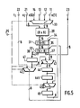
- FIGS. 4 and 5 we will now briefly describe an example of a microcontroller allowing an advantageous and very efficient implementation of the method according to the invention and an example of a calculation cell which can be incorporated in such a microcontroller.
- the devices are, in themselves, the subject respectively of European patent applications Nos. 90 203410.7 and 90 203412.3 filed on December 18, 1990, patent applications in which these devices are described in more detail.
- the microcontroller represented diagrammatically in FIG. 4 comprises a central unit (CPU) 15, a program memory (ROM) 16, a working memory (RAM) 17, a calculation cell symbolized by the broken line rectangle 18, as well as a state and command register unit (EC) 19 and a sequencer (SE) 20.
- the central unit 15 exchanges data with the program memory 16, the state and command register unit 19, the sequencer 20 by means of a data bus 7 and transmits address values to the program memory 16 by means of an address bus 8.
- the central unit 15 can also exchange data and addresses via the respective buses 7 and 8 with the working memory 17 but the accesses to the working memory 17 are not direct.
- the data bus 7 which is linked to the central unit 15 accesses the data port of the working memory 17 via a first input of a data switching multiplexer 4, the second input of which communicates with a so-called "local bus""10 whose role will be explained later.
- the address port of the working memory 17 is connected to the output of another so-called address switching multiplexer 5 of which four inputs are connected to the address bus 8, respectively: for the first input, via a register double 122-222 of addresses for an operand t, double register which is arranged in serial queue, for the second entry, via another double register 121-221 also arranged in serial queue for the address d 'an operand x, for the third entry, via a simple register 211 for the address of an operand a [] and finally, for the fourth entry, via another double register 123-223 for the address of a result of operation b.
- the address pointer registers 122, 121, 211, 123 can be loaded by the central processing unit 15 while the registers pointers 222, 221 and 223 are designed to receive the address values of their homologous registers in each of the corresponding queues and are then capable of being incremented or decremented automatically by the sequencer 20.
- the simple pointer register 211 can also , after loading by the central unit 15, be incremented or decremented automatically by the sequencer 20.
- the calculation cell 18 has four inputs 11, 12, 13 and 14 for operands a [1], a [2], a [3] and a [4] as well as inputs 21 and 22 for operands respectively x i and t i .
- Between the local bus 10 and the operand inputs 11, 12, 13, 14 are interposed registers respectively 311, 312, 313 and 314 in which the value of the mentioned operands is stored.
- Between the input 21 of the operand x i and the local bus 10 is interposed a pair of registers 321-421 arranged in serial queue, as well as between the input 22 of the operand t i and the local bus 10 is interposed a pair of registers 322-422 arranged in a queue.
- the calculation cell 18 also has an output 23 for a result b i which passes to the local bus 10 via an output register 323.
- the particularity of the microcontroller represented in FIG. 4 lies mainly in the fact that, thanks to the local bus 10, data can transit, via the data switching multiplexer 4, between the working memory 17 and the data ports of the cell. 18, and thus this cell can perform a series of calculations under the control of the sequencer 20 without intervention of the central unit 15. During this series of operations the central unit is able to reload the address pointers in the pointer registers 121, 122 and 123 for a series of subsequent calculations.
- all of the data processed is in a uniform 8-bit format.
- the calculation variables T and X are divided into 8-bit words which, at a rank of weight i constitute the operands x i and t i .
- these values are first loaded in two clock cycles into the registers 321 and 322 via the local bus 10.
- a third clock cycle is used to write into the memory of work 17 a result b i stored in the register 323.
- the calculation cell 18 can operate by cycle with 4 steps using the operands a [1] to a [4] or even by cycle with 3 steps, the operand a [ 4] not being used and input 14 not used.
- an operation of the calculation cell 18 with 3-step cycle is used, the operands a [1] to a [3] representing three successive bytes forming together the three bytes of the variable a i .
- the calculation cell 18 is capable of providing a single result b i following the 3-step calculation cycle returning to performing the operation a i .x i + t i .
- new values of the operands x i and t i are transferred simultaneously from the respective registers 321 and 322 to corresponding registers 421 and 422.
- Each of the calculation variables T, X, and B i being stored in the working memory 17 by bytes of consecutive addresses, these addresses are pointed to by the respective pointer registers 221, 222 and 223 by incrementation or decrementation under the control of the sequencer 20.
- a calculation is carried out at each step of the 4-step cycle while the local bus 10 is again occupied for the duration of two clock cycles for reloading the operand data in the registers 321 and 322 plus a cycle of clock for the transfer of the result from register 323 to the working memory 17.
- the local bus 10 remains unoccupied during a clock cycle on the 4 which form a calculation cycle.
- an operand a [4] - are reloaded in registers 311 to 313 (314) from an initial address loaded by the central unit in pointer register 211 which is then decremented or incremented to provide the following values of these operands from working memory 17.
- An alternative embodiment not shown in FIG. 4 consists in adding to the data register 323 receiving the result output b i , a stack of three short-circuitable buffer registers by means of a multiplexer .
- the 4 most significant bytes of the variable B i produced lastly by the calculation cell 18 can then, from the 3 buffer registers of said stack increased by register 323, be transferred directly and successively to registers 311, 312, 313 and 314 as operands for the implementation of a quasi-reduction modulo N which will follow. In this way the memory location represented by these 4 bytes of data can be saved.
- FIG. 5 indicates the internal diagram of a calculation cell 18 of FIG. 4.
- the inputs and outputs of the calculation cell are assigned the same reference signs as in FIG. 4.
- the data inputs 11 to 14 are applied to 4 inputs of a cyclically switched multiplexer 33, the output of which is applied to one of the two inputs of an 8 x 8 bit multiplier 30.
- the operand x i is applied to the second input of the same multiplier from input 21.
- the output of the multiplier 30 in 16-bit format is applied to one of the two inputs of a first adder 31 while a second entry in 8-bit format comes from data recycling means which will be described below.
- the output in 16-bit format of the first adder 31 is applied to one of the two inputs of a second adder 32, of 16 + 8 bits, the second input 35 of which can receive the value of the operand t i from of input 22 via a multiplexer 42.
- the second adder 32 has two outputs: an output 37 of the 8 least significant bits of the result capable of containing a result data item to be transmitted on output 23 and an output 38 of 8 bits of high weights which are stored in a buffer register 41.
- the output of the buffer register 41 is applied on the one hand to the second input of the multiplexer 42 and on the other hand to one of the two inputs of another multiplexer 43 the other 8-bit input of this other multiplexer being connected to the output 37 of the result low weights.
- the multiplexer 42 is positioned to select the operand input t i and the multiplexer 43, positioned to select the output of the buffer register 41. These positions are those which have been indicated symbolically in FIG. 5.
- the operand t i is presented to the addition in the second adder 32 and the result of the 8 least significant bits at output 37 of this adder is memorized via the output terminal 23 in register 323 ( Figure 4).
- the positioning of the multiplexers 42 and 43 is reversed so that the most significant values of the results at the output 38 of the second adder 32 are recycled upon addition to the input 35 of the second adder 32 after a delay corresponding to the parking of these values in the buffer register 41.
- the 8 least significant bits at the result output 37 of the second adder 32 are transferred to the register 44 constituting the head of the storage register stack where the values are successively transferred to the register which follows at each step. A suitable delay of 3 steps is therefore ensured for the recycling of these values at the addition in the first adder 31 on the input 34 of this adder.
- Such a calculation cell thus provides a single 8-bit result at output 23 per 4-step cycle, exploiting the operands a [1] to a [4] combined with the operands x i and t i .
- Intermediate results are recycled within this cell by the recycling means constituted essentially by the registers 41, 44, 445 and 45 provided with recycling switching means constituted by the multiplexers 42 and 43.
- Such a cell is also capable of operating in a 3-step cycle.
- a piece of information in the form of a particular 1 bit, loaded by the central unit 15 into the status and command register 19, commands the calculation cell not to use the operand a [4] so that the cyclic switching of the multiplexer 33 is limited to exploiting the operands a [1] to a [3].
- To ensure proper recycling of the intermediate data it is then necessary to reduce the stack of buffer registers 44, 445, 45 by 1 register, which is done by positioning the short-circuit multiplexer 450 in the position which makes it possible to avoid the register 445.
- microcontroller described briefly in FIG. 4 provided with a calculation cell as described in FIG. 5 is capable of implementing the method according to the invention for coding by the RSA method in a very effective. By proceeding in this way, a considerable number of tests is avoided, which can very significantly slow down the treatment operation.
- the invention also extends to any device provided with a central microcomputer unit controlled by a program, device in which this program implements the method described above.
Landscapes
- Physics & Mathematics (AREA)
- Engineering & Computer Science (AREA)
- General Physics & Mathematics (AREA)
- Mathematical Analysis (AREA)
- Mathematical Optimization (AREA)
- Pure & Applied Mathematics (AREA)
- Computational Mathematics (AREA)
- Theoretical Computer Science (AREA)
- Computing Systems (AREA)
- Mathematical Physics (AREA)
- General Engineering & Computer Science (AREA)
- Complex Calculations (AREA)
- Executing Machine-Instructions (AREA)
Applications Claiming Priority (2)
| Application Number | Priority Date | Filing Date | Title |
|---|---|---|---|
| FR9002274 | 1990-02-23 | ||
| FR9002274A FR2658932A1 (fr) | 1990-02-23 | 1990-02-23 | Procede de codage selon la methode dite rsa, par un microcontroleur et dispositif utilisant ce procede. |
Publications (2)
| Publication Number | Publication Date |
|---|---|
| EP0443679A1 true EP0443679A1 (de) | 1991-08-28 |
| EP0443679B1 EP0443679B1 (de) | 1998-12-09 |
Family
ID=9394076
Family Applications (1)
| Application Number | Title | Priority Date | Filing Date |
|---|---|---|---|
| EP91200332A Expired - Lifetime EP0443679B1 (de) | 1990-02-23 | 1991-02-18 | Verfahren zur Berechnung einer Operation des Typus A.X modulo N, in einem Kodierverfahren gemäss der RSA-Methode |
Country Status (5)
| Country | Link |
|---|---|
| US (1) | US5166978A (de) |
| EP (1) | EP0443679B1 (de) |
| JP (2) | JP3501468B2 (de) |
| DE (1) | DE69130581T2 (de) |
| FR (1) | FR2658932A1 (de) |
Cited By (4)
| Publication number | Priority date | Publication date | Assignee | Title |
|---|---|---|---|---|
| WO1993020503A1 (en) * | 1992-04-07 | 1993-10-14 | Thomson Consumer Electronics S.A. | Method and apparatus for modulo computation |
| FR2701323A1 (fr) * | 1993-02-08 | 1994-08-12 | Trt Telecom Radio Electr | Dispositif pour effectuer une division. |
| EP0863459A1 (de) * | 1997-03-06 | 1998-09-09 | Philips Patentverwaltung GmbH | Rechenschaltung zum Berechnen eines Quadrats |
| FR2839224A1 (fr) * | 2002-04-30 | 2003-10-31 | Gemplus Card Int | Procede pour effectuer une phase de multiplication modulaire de deux operandes en multiprecision et cryptoprocesseur pour la mise en oeuvre du procede |
Families Citing this family (30)
| Publication number | Priority date | Publication date | Assignee | Title |
|---|---|---|---|---|
| NZ240019A (en) * | 1991-09-30 | 1996-04-26 | Peter John Smith | Public key encrypted communication with non-multiplicative cipher |
| US5274707A (en) * | 1991-12-06 | 1993-12-28 | Roger Schlafly | Modular exponentiation and reduction device and method |
| US5299262A (en) * | 1992-08-13 | 1994-03-29 | The United States Of America As Represented By The United States Department Of Energy | Method for exponentiating in cryptographic systems |
| JPH0720778A (ja) * | 1993-07-02 | 1995-01-24 | Fujitsu Ltd | 剰余計算装置、テーブル作成装置および乗算剰余計算装置 |
| ATE189570T1 (de) * | 1994-02-24 | 2000-02-15 | Merdan Group Inc | Verfahren und einrichtung zum aufbau einer kryptographischen verbindung zwischen elementen eines systems |
| US5787172A (en) * | 1994-02-24 | 1998-07-28 | The Merdan Group, Inc. | Apparatus and method for establishing a cryptographic link between elements of a system |
| US5504817A (en) * | 1994-05-09 | 1996-04-02 | Yeda Research And Development Co. Ltd. At The Weizmann Institute Of Science | Method and apparatus for memory efficient variants of public key encryption and identification schemes for smart card applications |
| US5852665A (en) * | 1995-04-13 | 1998-12-22 | Fortress U & T Ltd. | Internationally regulated system for one to one cryptographic communications with national sovereignty without key escrow |
| IL113375A (en) * | 1995-04-13 | 1997-09-30 | Fortress U & T Ltd | Internationally regulated system for one to one cryptographic communications with national sovereignty without key escrow |
| US5932119A (en) | 1996-01-05 | 1999-08-03 | Lazare Kaplan International, Inc. | Laser marking system |
| DE69837036T2 (de) * | 1997-09-16 | 2007-10-18 | Koninklijke Philips Electronics N.V. | Verfahren und vorrichtung zur ausführung einer entschlüsselung mittels einer standardisierten modularen potenzierung zum vereiteln eines zeitangriffs |
| US6091821A (en) * | 1998-02-12 | 2000-07-18 | Vlsi Technology, Inc. | Pipelined hardware implementation of a hashing algorithm |
| AU1981400A (en) | 1999-12-16 | 2001-06-25 | Nokia Corporation | High throughput and flexible device to secure data communication |
| US7089420B1 (en) | 2000-05-24 | 2006-08-08 | Tracer Detection Technology Corp. | Authentication method and system |
| US7152047B1 (en) | 2000-05-24 | 2006-12-19 | Esecure.Biz, Inc. | System and method for production and authentication of original documents |
| US7162035B1 (en) | 2000-05-24 | 2007-01-09 | Tracer Detection Technology Corp. | Authentication method and system |
| US7167885B2 (en) * | 2002-03-22 | 2007-01-23 | Intel Corporation | Emod a fast modulus calculation for computer systems |
| US8171567B1 (en) | 2002-09-04 | 2012-05-01 | Tracer Detection Technology Corp. | Authentication method and system |
| WO2006110954A1 (en) * | 2005-04-20 | 2006-10-26 | Synaptic Laboratories Limited | Process of and apparatus for counting |
| US8229109B2 (en) | 2006-06-27 | 2012-07-24 | Intel Corporation | Modular reduction using folding |
| US7930337B2 (en) * | 2006-06-27 | 2011-04-19 | Intel Corporation | Multiplying two numbers |
| US7827471B2 (en) * | 2006-10-12 | 2010-11-02 | Intel Corporation | Determining message residue using a set of polynomials |
| US20080260153A1 (en) * | 2007-04-20 | 2008-10-23 | John Almeida | Symmetric and asymmetric cryptography using shadow numbers |
| US8689078B2 (en) | 2007-07-13 | 2014-04-01 | Intel Corporation | Determining a message residue |
| US8042025B2 (en) * | 2007-12-18 | 2011-10-18 | Intel Corporation | Determining a message residue |
| US7886214B2 (en) * | 2007-12-18 | 2011-02-08 | Intel Corporation | Determining a message residue |
| US9052985B2 (en) * | 2007-12-21 | 2015-06-09 | Intel Corporation | Method and apparatus for efficient programmable cyclic redundancy check (CRC) |
| US7995196B1 (en) | 2008-04-23 | 2011-08-09 | Tracer Detection Technology Corp. | Authentication method and system |
| EP2779519A1 (de) | 2013-03-11 | 2014-09-17 | Thomson Licensing | Verfahren und Vorrichtung zur fehlerbeständigen Potenzierung in kryptografischen Systemen |
| US10658455B2 (en) | 2017-09-28 | 2020-05-19 | Taiwan Semiconductor Manufacturing Co., Ltd. | Metal insulator metal capacitor structure having high capacitance |
Citations (4)
| Publication number | Priority date | Publication date | Assignee | Title |
|---|---|---|---|---|
| DE3138698A1 (de) * | 1981-09-29 | 1983-04-07 | Siemens AG, 1000 Berlin und 8000 München | Verfahren zur potenzierung grosser binaerzahlen in einer restklasse modulo n, insbesondere zur verschluesselung und entschluesselung digital dargestellter nachrichten |
| EP0208238A2 (de) * | 1985-07-10 | 1987-01-14 | Hitachi, Ltd. | Hochgeschwindigkeitsresiduberechnungsgerät |
| EP0258051A2 (de) * | 1986-08-28 | 1988-03-02 | Nortel Networks Corporation | Digitaler Signalprozessor mit Dividierfunktion |
| FR2613861A1 (fr) * | 1987-04-10 | 1988-10-14 | Pailles Jean Claude | Procede et controleur pour cryptographier un message selon un algorithme a cle publique |
Family Cites Families (3)
| Publication number | Priority date | Publication date | Assignee | Title |
|---|---|---|---|---|
| US5077793A (en) * | 1989-09-29 | 1991-12-31 | The Boeing Company | Residue number encryption and decryption system |
| US5121431A (en) * | 1990-07-02 | 1992-06-09 | Northern Telecom Limited | Processor method of multiplying large numbers |
| US5101431A (en) * | 1990-12-14 | 1992-03-31 | Bell Communications Research, Inc. | Systolic array for modular multiplication |
-
1990
- 1990-02-23 FR FR9002274A patent/FR2658932A1/fr active Pending
-
1991
- 1991-02-18 EP EP91200332A patent/EP0443679B1/de not_active Expired - Lifetime
- 1991-02-18 DE DE69130581T patent/DE69130581T2/de not_active Expired - Lifetime
- 1991-02-21 US US07/660,197 patent/US5166978A/en not_active Expired - Lifetime
- 1991-02-22 JP JP04879791A patent/JP3501468B2/ja not_active Expired - Lifetime
-
2002
- 2002-04-10 JP JP2002107977A patent/JP3467489B2/ja not_active Expired - Lifetime
Patent Citations (4)
| Publication number | Priority date | Publication date | Assignee | Title |
|---|---|---|---|---|
| DE3138698A1 (de) * | 1981-09-29 | 1983-04-07 | Siemens AG, 1000 Berlin und 8000 München | Verfahren zur potenzierung grosser binaerzahlen in einer restklasse modulo n, insbesondere zur verschluesselung und entschluesselung digital dargestellter nachrichten |
| EP0208238A2 (de) * | 1985-07-10 | 1987-01-14 | Hitachi, Ltd. | Hochgeschwindigkeitsresiduberechnungsgerät |
| EP0258051A2 (de) * | 1986-08-28 | 1988-03-02 | Nortel Networks Corporation | Digitaler Signalprozessor mit Dividierfunktion |
| FR2613861A1 (fr) * | 1987-04-10 | 1988-10-14 | Pailles Jean Claude | Procede et controleur pour cryptographier un message selon un algorithme a cle publique |
Non-Patent Citations (2)
| Title |
|---|
| COMPCON 1982, Washington, 20th - 23rd September 1982, pages 672-678, IEEE, New York, US; S. MIYAGUCHI: "Fast encryption algorithm for the RSA cryptographic system" * |
| ELECTRONICS LETTERS, vol. 23, no. 15, 16 juillet 1987, pages 794-795, Stevenage, Herts, GB; P.W. BAKER: "Fast computation of A * B modulo N" * |
Cited By (8)
| Publication number | Priority date | Publication date | Assignee | Title |
|---|---|---|---|---|
| WO1993020503A1 (en) * | 1992-04-07 | 1993-10-14 | Thomson Consumer Electronics S.A. | Method and apparatus for modulo computation |
| FR2701323A1 (fr) * | 1993-02-08 | 1994-08-12 | Trt Telecom Radio Electr | Dispositif pour effectuer une division. |
| EP0610996A1 (de) * | 1993-02-08 | 1994-08-17 | Philips Cartes Et Systemes | Gerät zum Ausführen einer Division |
| US5644639A (en) * | 1993-02-08 | 1997-07-01 | U.S. Philips Corporation | Device for carrying out a division |
| EP0863459A1 (de) * | 1997-03-06 | 1998-09-09 | Philips Patentverwaltung GmbH | Rechenschaltung zum Berechnen eines Quadrats |
| US6032169A (en) * | 1997-03-06 | 2000-02-29 | U.S. Philips Corporation | Arithmetic circuit for calculating a square |
| FR2839224A1 (fr) * | 2002-04-30 | 2003-10-31 | Gemplus Card Int | Procede pour effectuer une phase de multiplication modulaire de deux operandes en multiprecision et cryptoprocesseur pour la mise en oeuvre du procede |
| WO2003093974A3 (fr) * | 2002-04-30 | 2004-04-01 | Gemplus Card Int | Procede de multiplication modulaire |
Also Published As
| Publication number | Publication date |
|---|---|
| DE69130581D1 (de) | 1999-01-21 |
| JP2003029627A (ja) | 2003-01-31 |
| US5166978A (en) | 1992-11-24 |
| FR2658932A1 (fr) | 1991-08-30 |
| JP3501468B2 (ja) | 2004-03-02 |
| EP0443679B1 (de) | 1998-12-09 |
| JP3467489B2 (ja) | 2003-11-17 |
| DE69130581T2 (de) | 1999-06-24 |
| JPH04216588A (ja) | 1992-08-06 |
Similar Documents
| Publication | Publication Date | Title |
|---|---|---|
| EP0443679B1 (de) | Verfahren zur Berechnung einer Operation des Typus A.X modulo N, in einem Kodierverfahren gemäss der RSA-Methode | |
| EP0712072B1 (de) | Verfahren zur Ausführung von modularen Reduktion nach der Montgomery-Methode | |
| FR2758195A1 (fr) | Coprocesseur d'arithmetique modulaire comprenant deux circuits de multiplication operant en parallele | |
| EP0712071B1 (de) | Verfahren zur Verwendung der modularen Multiplikation nach der Montgomery-Methode | |
| EP0439855B1 (de) | Mikrokontroller zur schnellen Ausführung einer grossen Anzahl von Befehlen, die in Folgen von gleichartigen Befehlen zerlegbar sind | |
| EP2515228A1 (de) | Multiplikationsverfahren nach Montgomery | |
| FR2822260A1 (fr) | Procedes et dispositifs pour accelerer le temps de calcul d'un produit de montgomery d'un multiplication et d'une exponentiation modulaire | |
| EP0939362B1 (de) | Koprozessor für moduläre Arithmetik mit einer schnellen Ausführung von nicht-modulären Operationen | |
| EP0793165B1 (de) | Koprozessor für moduläre Arithmetik mit einer schnellen Ausführung von nicht-modulären Operationen | |
| EP0939363B1 (de) | Verfahren zur Ausführung der modularen Multiplikation nach der Montgomery-Methode | |
| EP0785503B1 (de) | Verfahren zum Erzeugen eines Fehlerkorrekturparameters bezüglich der Verwendung von modularen Operationen nach der Montgomery-Methode | |
| EP1012703B1 (de) | Modulo-arithmetischer koprozessor mit einer schaltung für die division ganzer zahlen | |
| EP0286489B1 (de) | Verfahren und Kontrollgerät zur Verschlüsselung einer Nachricht gemäss eines Algorithmus mit öffentlichem Schlüssel | |
| EP0778518B1 (de) | Verfahren zum Erzeugen eines Parameters J0 bezüglich der Verwendung von modularen Operationen nach der Montgomery-Methode | |
| EP0927928B1 (de) | Verbessertes Verfahren zum Erzeugen eines Parameters J0 bezüglich der Verwendung von modularen Operationen nach der Montgomery-Methode | |
| EP0784262B1 (de) | Einrichtung und Verfahren zur Verbesserung der Verarbeitungsgeschwindigkeit eines Koprozessors für moduläre Arithmetik | |
| EP0785502A1 (de) | Verfahren zum Erzeugen eines Fehlerkorrekturparameters bezüglich der Verwendung von modularen Operationen nach der Montgomery-Methode | |
| FR2842051A1 (fr) | Procede de cryptographie incluant le calcul d'une multiplication modulaire au sens de montgomery et entite electronique correspondante | |
| EP0902359B1 (de) | Verfahren und Anordnung zur Durchführung ganzzahliger Divisionsoperationen mit einem modulo-arithmetischen Koprozessor | |
| EP0625745A2 (de) | Von internem Überlauf freier Bit-serieller Multiplizierer | |
| EP0435399B1 (de) | Arithmetische Verarbeitungseinheit, zu verbinden mit einer Mikroprozessor-Zentraleinheit | |
| FR2745646A1 (fr) | Coprocesseur d'arithmetique modulaire permettant de realiser des operations non modulaires rapidement | |
| WO2003093974A2 (fr) | Procede de multiplication modulaire | |
| WO2004015559A2 (fr) | Procede pour accelerer des calculs en arithmetique modulaire |
Legal Events
| Date | Code | Title | Description |
|---|---|---|---|
| PUAI | Public reference made under article 153(3) epc to a published international application that has entered the european phase |
Free format text: ORIGINAL CODE: 0009012 |
|
| AK | Designated contracting states |
Kind code of ref document: A1 Designated state(s): DE FR GB |
|
| 17P | Request for examination filed |
Effective date: 19920228 |
|
| 17Q | First examination report despatched |
Effective date: 19960711 |
|
| GRAG | Despatch of communication of intention to grant |
Free format text: ORIGINAL CODE: EPIDOS AGRA |
|
| GRAG | Despatch of communication of intention to grant |
Free format text: ORIGINAL CODE: EPIDOS AGRA |
|
| GRAH | Despatch of communication of intention to grant a patent |
Free format text: ORIGINAL CODE: EPIDOS IGRA |
|
| RAP3 | Party data changed (applicant data changed or rights of an application transferred) |
Owner name: KONINKLIJKE PHILIPS ELECTRONICS N.V. |
|
| GRAH | Despatch of communication of intention to grant a patent |
Free format text: ORIGINAL CODE: EPIDOS IGRA |
|
| GRAA | (expected) grant |
Free format text: ORIGINAL CODE: 0009210 |
|
| AK | Designated contracting states |
Kind code of ref document: B1 Designated state(s): DE FR GB |
|
| REF | Corresponds to: |
Ref document number: 69130581 Country of ref document: DE Date of ref document: 19990121 |
|
| GBT | Gb: translation of ep patent filed (gb section 77(6)(a)/1977) |
Effective date: 19990122 |
|
| PLBE | No opposition filed within time limit |
Free format text: ORIGINAL CODE: 0009261 |
|
| STAA | Information on the status of an ep patent application or granted ep patent |
Free format text: STATUS: NO OPPOSITION FILED WITHIN TIME LIMIT |
|
| 26N | No opposition filed | ||
| REG | Reference to a national code |
Ref country code: GB Ref legal event code: IF02 |
|
| REG | Reference to a national code |
Ref country code: GB Ref legal event code: 746 Effective date: 20021014 |
|
| REG | Reference to a national code |
Ref country code: FR Ref legal event code: D6 |
|
| REG | Reference to a national code |
Ref country code: GB Ref legal event code: 732E |
|
| REG | Reference to a national code |
Ref country code: GB Ref legal event code: 732E |
|
| REG | Reference to a national code |
Ref country code: FR Ref legal event code: TP |
|
| REG | Reference to a national code |
Ref country code: FR Ref legal event code: GC |
|
| REG | Reference to a national code |
Ref country code: GB Ref legal event code: 732E Free format text: REGISTERED BETWEEN 20090618 AND 20090624 |
|
| REG | Reference to a national code |
Ref country code: FR Ref legal event code: GC |
|
| PGFP | Annual fee paid to national office [announced via postgrant information from national office to epo] |
Ref country code: FR Payment date: 20100223 Year of fee payment: 20 |
|
| PGFP | Annual fee paid to national office [announced via postgrant information from national office to epo] |
Ref country code: GB Payment date: 20100202 Year of fee payment: 20 Ref country code: DE Payment date: 20100226 Year of fee payment: 20 |
|
| REG | Reference to a national code |
Ref country code: GB Ref legal event code: 732E Free format text: REGISTERED BETWEEN 20101007 AND 20101013 |
|
| REG | Reference to a national code |
Ref country code: DE Ref legal event code: R071 Ref document number: 69130581 Country of ref document: DE |
|
| REG | Reference to a national code |
Ref country code: GB Ref legal event code: PE20 Expiry date: 20110217 |
|
| PG25 | Lapsed in a contracting state [announced via postgrant information from national office to epo] |
Ref country code: GB Free format text: LAPSE BECAUSE OF EXPIRATION OF PROTECTION Effective date: 20110217 |
|
| PG25 | Lapsed in a contracting state [announced via postgrant information from national office to epo] |
Ref country code: DE Free format text: LAPSE BECAUSE OF EXPIRATION OF PROTECTION Effective date: 20110218 |