EP0444246B1 - Appareil et procédé pour mesurer l'adsorption ou la désorption - Google Patents
Appareil et procédé pour mesurer l'adsorption ou la désorption Download PDFInfo
- Publication number
- EP0444246B1 EP0444246B1 EP90121237A EP90121237A EP0444246B1 EP 0444246 B1 EP0444246 B1 EP 0444246B1 EP 90121237 A EP90121237 A EP 90121237A EP 90121237 A EP90121237 A EP 90121237A EP 0444246 B1 EP0444246 B1 EP 0444246B1
- Authority
- EP
- European Patent Office
- Prior art keywords
- gas
- containing means
- sample
- pressure
- sample containing
- Prior art date
- Legal status (The legal status is an assumption and is not a legal conclusion. Google has not performed a legal analysis and makes no representation as to the accuracy of the status listed.)
- Expired - Lifetime
Links
- 238000000034 method Methods 0.000 title claims description 30
- 238000002336 sorption--desorption measurement Methods 0.000 title description 2
- 238000001179 sorption measurement Methods 0.000 claims description 51
- 238000003795 desorption Methods 0.000 claims description 40
- 238000005259 measurement Methods 0.000 claims description 28
- 239000007787 solid Substances 0.000 claims description 14
- 239000002156 adsorbate Substances 0.000 claims description 10
- 101150087584 PPT1 gene Proteins 0.000 claims description 4
- 101150023411 PPT2 gene Proteins 0.000 claims description 4
- 239000007789 gas Substances 0.000 description 116
- 239000011148 porous material Substances 0.000 description 17
- IJGRMHOSHXDMSA-UHFFFAOYSA-N Atomic nitrogen Chemical compound N#N IJGRMHOSHXDMSA-UHFFFAOYSA-N 0.000 description 13
- 239000002245 particle Substances 0.000 description 6
- 238000002360 preparation method Methods 0.000 description 6
- 229910001873 dinitrogen Inorganic materials 0.000 description 5
- 239000003507 refrigerant Substances 0.000 description 5
- 229910052757 nitrogen Inorganic materials 0.000 description 4
- 238000010923 batch production Methods 0.000 description 3
- 238000009826 distribution Methods 0.000 description 3
- 239000012770 industrial material Substances 0.000 description 3
- 239000007788 liquid Substances 0.000 description 3
- 230000002411 adverse Effects 0.000 description 2
- 239000007792 gaseous phase Substances 0.000 description 2
- 230000000704 physical effect Effects 0.000 description 2
- 101100084118 Caenorhabditis elegans ppt-1 gene Proteins 0.000 description 1
- VYPSYNLAJGMNEJ-UHFFFAOYSA-N Silicium dioxide Chemical compound O=[Si]=O VYPSYNLAJGMNEJ-UHFFFAOYSA-N 0.000 description 1
- 102220493453 Sodium/calcium exchanger 3_P13V_mutation Human genes 0.000 description 1
- 239000003463 adsorbent Substances 0.000 description 1
- 239000000919 ceramic Substances 0.000 description 1
- 238000010586 diagram Methods 0.000 description 1
- 239000011521 glass Substances 0.000 description 1
- 230000005484 gravity Effects 0.000 description 1
- 239000001307 helium Substances 0.000 description 1
- 229910052734 helium Inorganic materials 0.000 description 1
- SWQJXJOGLNCZEY-UHFFFAOYSA-N helium atom Chemical compound [He] SWQJXJOGLNCZEY-UHFFFAOYSA-N 0.000 description 1
- 239000011261 inert gas Substances 0.000 description 1
- -1 ion-exchangers Substances 0.000 description 1
- 238000004519 manufacturing process Methods 0.000 description 1
- QSHDDOUJBYECFT-UHFFFAOYSA-N mercury Chemical compound [Hg] QSHDDOUJBYECFT-UHFFFAOYSA-N 0.000 description 1
- 229910052753 mercury Inorganic materials 0.000 description 1
- 239000002994 raw material Substances 0.000 description 1
- 230000000630 rising effect Effects 0.000 description 1
- 229920006395 saturated elastomer Polymers 0.000 description 1
- 239000000741 silica gel Substances 0.000 description 1
- 229910002027 silica gel Inorganic materials 0.000 description 1
- 239000011949 solid catalyst Substances 0.000 description 1
Images

Classifications
-
- G—PHYSICS
- G01—MEASURING; TESTING
- G01N—INVESTIGATING OR ANALYSING MATERIALS BY DETERMINING THEIR CHEMICAL OR PHYSICAL PROPERTIES
- G01N15/00—Investigating characteristics of particles; Investigating permeability, pore-volume or surface-area of porous materials
- G01N15/08—Investigating permeability, pore-volume, or surface area of porous materials
- G01N15/088—Investigating volume, surface area, size or distribution of pores; Porosimetry
- G01N15/0893—Investigating volume, surface area, size or distribution of pores; Porosimetry by measuring weight or volume of sorbed fluid, e.g. B.E.T. method
Definitions
- This invention relates to an apparatus and method for measuring adsorption and desorption of a gas in and from a solid sample according to the first part of claim 1.
- various particles such as solid catalysts, adsorbents, ion-exchangers, and ceramics are widely used as industrial materials. These particles vary in their physical properties such as specific surface area, pore volume and pore diameter distribution according to raw materials and manufacturing conditions. Consequently, the particles vary in industrial performance. When the particles are used as industrial materials, the specific surface area, the pore volume, and the pore diameter distribution of the particles should be precisely known.
- the gaseous-phase adsorption method is used for measuring the physical properties of industrial-material particles.
- inert gas such as nitrogen gas
- a sample physically adsorbs the adsorbate gas.
- Variances in the pressure and volume of the adsorbate gas are obtained for measuring the adsorption of the sample.
- variances with time in adsorption pressure values and adsorbate gas volume at constant temperature are used.
- the configuration of adsorption isotherm, or hysteresis, seen on the adsorption isotherm between increase and decrease of the adsorption is, therefore, used.
- a batch-process apparatus In the related-art method, a batch-process apparatus is used.
- the batch-process apparatus comprises a measuring portion for measuring volume and pressure of gas and a sample container connected through a valve to the measuring portion.
- the measuring portion is provided with valves for supplying and exhausting gas to and from the measuring portion, respectively.
- a volume M of gas is first introduced into the measuring portion, and the measuring portion is connected to the sample container.
- a series of processes for measuring pressure values is repeated.
- the volume M of gas is increased.
- the adsorption is calculated from the pressure values, the volume of the measuring portion, and the like.
- the measuring portion is evacuated, and the measuring portion is connected to the sample container.
- a series of processes for measuring values is repeated. At each of the processes, desorbed gas is exhausted from the measuring portion. The desorption is calculated from the pressure values, the volume of the measuring portion, and the like.
- a method for measuring adsorption and desorption using a mass flow controller is proposed in Japan Published Unexamined Patent Application No. 61-102538.
- This method is different from the above method using the batch-process apparatus in that gas is continuously fed little by little into a vacuum sample container with the mass flow controller.
- the flow rate of gas is substantially kept constant.
- adsorption and desorption of gas by a sample are calculated based on the flow rate of gas and measured variances in the pressure of the sample container.
- Adsorption isotherm is thus obtained.
- the method when gas is introduced into the sample container, the adsorption of the sample in the sample container is kept in equibrium. Pressure values are measured at several points of time from the beginning till the end of the introduction of gas into the sample container. Excessive time is not required for obtaining pressure values.
- An adsorption isotherm can be obtained in a relatively short period of time.
- the adsorption of the sample is calculated in a predetermined equation by using the flow rate of gas.
- the mass flow controller controls the flow rate of gas substantially constant at a target value.
- the mass flow controller should be frequently adjusted and calibrated so that the flow rate of gas should not deviate from the target value and the adsorption can precisely be calculated.
- the flow rate of gas cannot be kept constant, and it sometimes deviates from the target value. Consequently, precise calculation of adsorption or desorption cannot result.
- the object of the present invention is to provide an apparatus and a method for measuring adsorption and desorption more exactly and precisely obtain an adsorption and desorption isotherm. This object is attained by the features of the apparatus claim 1 and the method claim 4.
- Fig. 1 is a block diagram embodying an apparatus for measuring adsorption and desorption of the present invention.
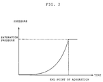
- Fig. 2 is a graph showing variances in pressure with time during measurement of adsorption.
- the adsorption/desorption measuring apparatus comprises a sample container 10, a mass flow controller 11, a gas reservoir 12, a gas bomb 13, two pressure gauges 14, 16, and a vacuum pump 15.
- a solid sample is introduced into the sample container 10.
- the mass flow controller 11 can continuously supply a specified volume of gas to the sample container 10.
- the sample container 10 is connected via piping H1 through the mass flow controller 11 and the gas reservoir 12 to the gas bomb 13.
- the pressure gauge 14 and the vacuum pump 15 are, respectively, connected through pipings H2 and H3 to points A and C of the piping H1 connecting the sample container 10 and the mass flow controller 11.
- the pressure gauge 16 is connected through a piping H4 to the gas reservoir 12.
- One end of a piping H5 opens to the atmosphere, and the other end of the piping H5 goes to the vacuum pump 15.
- the pipings H4 and H5 intersect at a point B.
- a piping H6 is laid from a point between the mass flow controller 11 and the gas reservoir 12 to the sample container 10.
- valves V1, V2, and V3 are provided on the piping H1 between the sample container 10 and the mass flow controller 11.
- the piping H1 further includes a valve V4 between the mass flow controller 11 and the gas reservoir 12, and a valve V5 between the gas reservoir 12 and the gas bomb 13.
- a valve V6 is provided on the piping H6 which extends from the point between the mass flow controller 11 and the gas reservoir 12 to the sample container 10.
- Valves V7 and V10 are provided on the piping H3 between the point A of the piping H1 and the vacuum pump 15, a valve V8 is provided on the piping H5 between the vacuum pump 15 and the intersection B, and a valve V9 is provided at the end of the piping H5 which end opens to the atmosphere.
- the sample container 10 is soaked in a refrigerant tank 17, so that the sample container 10 is kept at constant temperature.
- the liquid level in the refrigerant tank 17 is kept constant, thus preventing the volume in the sample container 10 from changing.
- the mass flow controller 11 can be mechanical or electrical.
- the flow rate of the mass flow controller 11 should be prevented from varying with the fluctuation in the primary and/or the secondary pressure.
- the operating range of differential pressure between the primary and the secondary sides of the mass flow controller 11 should be wide.
- the gas reservoir 12 for storing gas from the gas bomb 13 can be kept constant around room temperature of 25°C.
- the gas reservoir 12 should contain the predetermined volume at minimum so that the differential pressure of the mass flow controller 11 adjoining the gas reservoir 12 should be kept in the predetermined operating range of the mass flow controller 11.
- the predetermined volume of the gas reservoir 12 varies with the weight and the pore volume of the sample.
- the measurement for this embodiment is executed as follows:
- the pressure of the sample container 10, which is equal to the secondary pressure of the mass flow controller 11, should equal atmospheric pressure of about 1kg/cm at the end of the measurement as described later.
- the residual pressure at the side of the gas reservoir 12 or the primary pressure of the mass flow controller 11 should be 1.4kg/cmA at minimum, thereby equaling the minimum differential pressure value of 0.4kg/cmA in the operating range, plus the atmospheric pressure of 1kg/cmA.
- the volume Vol of the gas reservoir 12 should exceed the calculated value of 420ml.
- VMIN (Vol 1 +Vol 2 )/(P1-P2)
- the actual volume of the gas reservoir 12 is set from equal to or ten times, and preferably one and half times to three times, as large as the reference value VMIN.
- Nitrogen adsorbed in pores of the sample is almost in a liquid condition. Nitrogen has a density of 0.808 and a molecular weight of 28.
- the volume of nitrogen adsorbed in one gram of the sample with a pore volume of 1ml is 1ml in a liquid form.
- the dead volume of 20ml is added to the calculated volume of 646ml, the necessary exhaust gas volume is 666ml, about 670ml.
- the pressure gauge 16 continuously or intermittently measures absolute pressure of the gas reservoir 12.
- the pressure gauge 14 continuously or intermittently measures the absolute pressure of the sample container 10.
- semiconductor-type pressure transducers or the like can read the absolute pressure of the gas reservoir 12 and the sample container 10 through computers and record the absolute pressure on recorders.
- the vacuum pump 15 exhausts gas from the sample container 10 in preparation for measurement of gas adsorbed in the sample.
- the pressure gauges 14 and 16 are calibrated in the method described later with the vacuum pump 15, the valves V8, V9 and the like.
- valves V1, V2, V3 and V6 switch the measuring apparatus for this embodiment between the system for measuring the adsorption of the sample and that for measuring the desorption of the sample.
- the pressure gauges 14 and 16 are calibrated.
- the valves V1, V3, V4, V5, V6, and V9 are closed, the valves V2, V7, V8, and V10 are opened, and the gas reservoir 12 is evacuated to the maximum, about 0kg/cmA, with the vacuum pump 15.
- the pressure gauges 14 and 16 are adjusted to zero.
- the vacuum pump 15 is stopped, the valve V9 is opened to the atmosphere, and the readings on the pressure gauges 14 and 16 are adjusted to the atmospheric pressure precisely measured with a mercury barometer, an aneroid barometer or other barometers.
- the pressure gauge 14 may be opened to the atmosphere by detaching the sample container 10 before measuring the atmospheric pressure.
- Volume V o of the gas reservoir 12 is the sum of the volume of the gas reservoir 12 and that of the piping from the gas reservoir 12 to the mass flow controller 11.
- a sample container (not shown) with a predetermined volume is connected to the valve V9.
- Volume Vs of the sample container should be almost the same as that of the gas reservoir 12.
- the volume of the sample container should be measured at predetermined temperature of 25°C.
- the valves V4, V8 and V9 are opened, and the valves V5, V6 and V7 are closed.
- the flow rate of the mass flow controller 11 is set to zero.
- the sample container as well as the gas reservoir 12 are evacuated with the vacuum pump 15. After the valves V8 and V9 are closed and the valve 5 is opened, nitrogen gas is introduced into the gas reservoir 12. Pressure P0 of the gas reservoir 12 in stable condition is measured with the pressure gauge 16. The valve V9 is then opened, and gas is introduced into the sample container.
- Air should be sufficiently circulated around the gas reservoir 12, the pressure gauge 16, the piping H1 and the like so that temperature should be kept constant.
- the flow through the mass flow controller 11 should be shut off. If the flow cannot be shut off in the structure of the mass flow controller 11, the volume V o of gas can be measured as follows. First, the sample container 10 with the predetermined volume is connected to the valve V1, and the refrigerant tank 17 is detached. After gas is introduced into the gas reservoir 12 in the same way as aforementioned, the valves V1, V2, V3 and V7 are opened, the valve V6 is kept closed, and the mass flow controller 11 is operated. When the valve V7 is closed, pressures on the pressure gauges 16 and 14 are read as pressures P11 and P21, respectively.
- pressures on the pressure gauges 16 and 14 are read as pressures P12 and P22, respectively. Subsequently, the sample container 10 is detached from the valve V1, and a connection rod with no content is connected to the valve V1. In the same way as aforementioned, variances in the pressures are obtained with the pressure gauges 16 and 14. Specifically, the initial pressures of the pressure gauges 16 and 14 are read as P13 and P23, respectively, and the pressures after appropriate time period are read as P14 and P24, respectively.
- V o Vs/[(P11-P12/P22-P12)-(P13-P14/P24-P23)]
- the sample container 10 After connecting the sample container 10 to the valve V1, the sample container 10 is soaked in the refrigerant tank 17. Subsequently, in the same way as mentioned in above preparation 2, pressures P31, P32, P41 and P42 corresponding to the pressures P11, P12, P21, P22, respectively, are obtained. Based on these pressures and the obtained values of Vs and V o , the dead volume Vt in standard condition is obtained from equation (1). After obtaining pressures P33, P34, P43 and P44 corresponding to the pressures P13, P14, P23, P24, respectively, the dead volume Vt can be obtained from equation (2).
- the specified sample is inserted in the sample container 10, and gas is introduced and stored in the gas reservoir 12 in the same way as mentioned in above preparation 3. Subsequently, gas is run from the gas reservoir 12 through the mass flow controller 11 in operation condition to the sample container 10. As time elapses after gas begins to flow, pressures of the gas reservoir 12 and the sample container 10 are measured with the pressure gauges 16 and 14, respectively.
- Variances with time in the pressures of the gas reservoir 12 and the sample container 10 are continuously and automatically recorded on the recorder with a microcomputer connected to the pressure gauges 16 and 14.
- Total dead volume Vtt which is the sum of the dead volume Vt and the dead volume Vol2 of the sample container 10, varies with the volume of the sample under measurement.
- the dead volume Vt can be measured by using gas which is not adsorbed into the sample, such as helium gas and the like.
- the dead volume Vt can be calculated from the refrigerant temperature and the true specific gravity of the sample. Other appropriate methods may be used.
- the mass Qc of gas exhausted from the gas reservoir 12 to the sample container 10 is precisely calculated at a given time t. Based on the mass Qc and the pressure value of the sample container 10 measured with the pressure gauge 14, adsorption Qs of the sample is calculated.
- the graph in Fig. 2 shows the pressure values measured as time passes.
- the end-point value of the adsorption can be clearly identified by intersecting the extension line of saturation pressure with the rising curve of the adsorption in Fig. 2.
- desorption of the sample can also be calculated.
- the measurement of desorption with the apparatus after the measurement of the adsorption will now be explained.
- valves V8 and V10 After measuring the adsorption of the sample, the valves V8 and V10 are opened, the valves V7, V4, V5 and V9 are kept closed, and the gas reservoir 12 is evacuated with the vacuum pump 15. Subsequently, the valves V7, V3, V6 and V1 are opened, the valves V4 and V2 are closed, the mass flow controller 11 is operated, and values on the pressure gauges 14 and 16 are recorded.
- the desorption isotherm is obtained by plotting the value Ppt2 of the pressure gauge 14 at time t1 and value Qso-Qt obtained by subtracting the desorption Qt at time t1 from desorption Qso at the saturation pressure.
- the volume Vol3 of the gas reservoir 12 at the time of desorption is calculated from variances in pressure when the sample container with the known volume and a glass rod with no volume are attached to the valve V1 and are thus connected through the mass flow controller 11 to the gas reservoir 12.
- Silica gel was used as the sample, and nitrogen gas was used as adsorbate.
- the actual mass flow rate was calculated between 2.23SCCM and 2.25SCCM based on the drop in the pressure of the gas reservoir 12.
- the specific surface area and the pore volume of the sample were calculated.
- the specific surface area of the sample was calculated based on the B.E.T. adsorption isotherm.
- the pore volume of the sample was obtained from the adsorption corresponding to the relative pressure of 1.0(P/P00). Measurement No.
- the specific surface area of the sample varied widely between 633m/g and 736m/g.
- the pore volume of the sample also varied widely between 0.345ml/g and 0.452ml/g.
- the mass flow controller 11 had to be adjusted several times.
Landscapes
- Chemical & Material Sciences (AREA)
- Biochemistry (AREA)
- General Physics & Mathematics (AREA)
- Health & Medical Sciences (AREA)
- Life Sciences & Earth Sciences (AREA)
- Analytical Chemistry (AREA)
- Dispersion Chemistry (AREA)
- General Health & Medical Sciences (AREA)
- Physics & Mathematics (AREA)
- Immunology (AREA)
- Pathology (AREA)
- Sampling And Sample Adjustment (AREA)
- Other Investigation Or Analysis Of Materials By Electrical Means (AREA)
- Investigating Or Analyzing Materials Using Thermal Means (AREA)
- Separation Of Gases By Adsorption (AREA)
Claims (6)
- Appareil pour mesurer l'adsorption et la désorption d'un gaz dans, et à partir d'un échantillon solide, comprenant:un moyen contenant l'échantillon (10) présentant un volume prédéterminé Vol2 pour contenir l'échantillon solide et le gaz,un moyen contenant du gaz (12) présentant un volume prédéterminé Vo pour contenir le gaz,un moyen d'échappement (15) pour assurer l'échappement, de manière sélective, du gaz à partir du moyen contenant l'échantillon (10) ou du moyen contenant le gaz,un moyen d'alimentation en gaz (11) pour fournir, de manière continue et sélective, le gaz à un certain débit à partir du moyen contenant le gaz (12) vers le moyen contenant l'échantillon (10) ou à partir du moyen contenant l'échantillon (10) vers le moyen contenant le gaz (12),un premier moyen de mesure de la pression (16) pour mesurer la pression du gaz dans le moyen contenant le gaz (12); etun deuxième moyen de mesure de la pression (14) pour mesurer la pression du gaz dans le moyen contenant l'échantillon (10),un moyen de calcul pour calculer l'adsorption et la désorption en fonction du débit de gaz entre le moyen contenant du gaz (12) et le moyen contenant l'échantillon (10), la pression mesurée par le deuxième moyen de mesure de pression (14), et le volume Vol2 du moyen contenant l'échantillon (10),caractérisé par le moyen de calcul du débit pour calculer le débit de gaz à partir du moyen contenant du gaz (12) dans le moyen contenant l'échantillon (10) en déterminant la masse Qc du gaz fournie pour le moyen d'alimentation en gaz (11) à partir du moyen contenant du gaz (12) dans le moyen contenant l'échantillon (10) dans le temps; caractériséen ce que la masse Qc gaz fournie à partir du moyen contenant du gaz (12) vers le moyen contenant l'échantillon (10) est calculée selon l'équation suivante:
 où Ps est la pression dans le moyen contenant du gaz (12) lorsque le moyen d'alimentation en gaz (11) commence à fournir du gaz à partir du moyen contenant du gaz (12) dans le moyen contenant l'échantillon (10), Pt1 est la pression dans le moyen contenant du gaz (12) à un moment donné t, T1 est la température dans le moyen contenant du gaz (12), et R est une constante,par des moyens de calcul de l'adsorption pour calculer la quantité d'adsorbat sur l'échantillon solide Qs lorsque le moyen d'alimentation en gaz (11) fournit du gaz à partir du moyen contenant du gaz (12) vers le moyen contenant l'échantillon (10) en fonction du débit de gaz à partir du moyen contenant du gaz (12) dans le moyen contenant l'échantillon (10) selon l'équation suivante:
 où Pt2 est la pression dans le moyen contenant l'échantillon (10) à un moment donné t, Vtt est la somme du volume Vol2 du moyen contenant l'échantillon (10) et d'un volume mort Vt dans le système, T2 est la température du système au moment où le volume mort Vt est mesuré, et W est le poids de l'échantillon,par un moyen de calcul du débit pour calculer le débit de gaz à partir du moyen contenant l'échantillon (10) dans le moyen contenant le gaz (12) en déterminant la masse Qd du gaz fournie par le moyen d'alimentation en gaz (11) à partir du moyen contenant l'échantillon (10) dans le moyen contenant le gaz (12) dans le temps;la masse Qd du gaz fournie à partir du moyen contenant l'échantillon (10) vers le moyen contenant le gaz (12) étant calculée selon l'équation suivante:
 où Ppt1 est la pression dans le moyen contenant du gaz (12) mesurée au moment t1, Pps est la pression dans le moyen contenant du gaz (12) au début de la mesure, vol3 est le volume du moyen contenant du gaz (12) au moment de la désorption, T1 est la température du moyen contenant le gaz (12), et R est une constante, et un moyen de calcul de la désorption pour calculer la quantité d'adsorbat Qt à partir de l'échantillon solide après le calcul de l'adsorption pendant que le moyen d'alimentation en gaz (11) fournit du gaz à partir du moyen contenant l'échantillon (10) vers le moyen contenant du gaz (12) en fonction du débit de gaz à partir du moyen contenant l'échantillon (10) dans le moyen contenant du gaz (12) selon l'équation suivante:
 où Ppt2 est la pression dans le moyen contenant l'échantillon (10) à un moment donné t2, Vtt est la somme du volume Vol2 du moyen contenant l'échantillon (10) et d'un volume mort Vt dans le système, T2 est la température du système au moment où le volume mort Vt est mesuré, et W est le poids de l'échantillon.
 - Appareil selon la revendication 1, caractérisé en ce qu'il comprend, en outre, des moyens de calcul de l'isotherme pour calculer un isotherme d'adsorption à partir de l'adsorption calculée en des points successifs dans le temps.
- Appareil selon la revendication 1 ou 2, caractérisé en ce qu'il comprend, en outre, un moyen de calcul de l'isotherme pour calculer un isotherme de désorption à partir de la désorption calculée en des points successifs dans le temps.
- Procédé de mesure de l'adsorption et de la désorption du gaz dans et à partir d'un échantillon solide, utilisant l'appareil selon l'une quelconque des revendications 1 à 3, caractérisé par les étapes suivantes:introduction de l'échantillon solide dans un moyen contenant l'échantillon (10) présentant un volume prédéterminé tout en assurant simultanément l'échappement du gaz à partir du moyen contenant l'échantillon (10),alimentation continue du gaz à partir d'un moyen contenant du gaz (12) présentant un volume prédéterminé dans le moyen contenant l'échantillon (10), le gaz dans le moyen contenant le gaz (12) étant maintenu à une température prédéterminée,mesure des pressions dans le moyen contenant l'échantillon (10) et le moyen contenant le gaz (12) pendant l'alimentation en continu du gaz depuis le moyen contenant le gaz (12) dans le moyen contenant l'échantillon (10),calcul d'un débit de gaz dans le moyen contenant l'échantillon (10) en fonction de la pression et du volume du moyen contenant le gaz (12) en déterminant la masse Qc du gaz fournie par le moyen d'alimentation en gaz (11) à partir du moyen contenant le gaz (12) dans le moyen contenant l'échantillon (10) dans le temps; et en ce quela masse Qc de gaz fournie depuis le moyen contenant le gaz (12) au moyen contenant l'échantillon (10) est calculée selon l'équation suivante:
 où Ps est la pression dans le moyen contenant le gaz (12) lorsque le moyen d'alimentation en gaz (11) commence à fournir du gaz depuis le moyen contenant le gaz (12) dans le moyen contenant l'échantillon (10), Pt1 est la pression dans le moyen contenant le gaz (12) à un moment donné t, T1 est la température dans le moyen contenant le gaz (12) et R est une constante,obtention de l'adsorption de l'échantillon solide Qs en fonction du débit, la pression dans le moyen contenant l'échantillon (10) et le volume du moyen contenant l'échantillon (10) à l'aide de l'équation suivante:
 où Pt2 est la pression dans le moyen contenant l'échantillon (10) à un moment donné t, Vtt est la somme du volume vol2 du moyen contenant l'échantillon (10) et un volume mort Vt dans le système, T2 est la température du système au moment où le volume mort Vt est mesuré, et W est le poids de l'échantillon,alimentation continue en gaz à partir du moyen contenant l'échantillon (10) dans le moyen contenant le gaz (12), le gaz dans le moyen contenant l'échantillon (10) étant maintenu à une température prédéterminée,mesure des pressions dans le moyen contenant l'échantillon (10) et le moyen contenant le gaz (12) pendant l'alimentation en continu du gaz à partir du moyen contenant l'échantillon (10) dans le moyen contenant le gaz (12),calcul d'un débit de gaz dans le moyen contenant le gaz (12) en fonction de la pression et du volume du moyen contenant le gaz (12) en déterminant le Qd de masse du gaz fourni par le moyen d'alimentation en gaz (11) à partir du moyen contenant l'échantillon (10) dans le moyen contenant le gaz (12) dans le temps, et en ce quela masse Qd du gaz fournie à partir du moyen contenant l'échantillon (10) vers le moyen contenant le gaz (12) est calculée selon l'équation suivante:
 où Ppt1 est la pression dans le moyen contenant le gaz (12) mesurée au moment t1, Pps est la pression dans le moyen contenant le gaz (12) au début de la mesure, Vol3 est le volume du moyen contenant le gaz (12) au moment de la désorption, T1 est la température du moyen contenant le gaz (12) et R est une constante,obtention de la désorption de l'échantillon solide en fonction du débit, de la pression dans le moyen contenant l'échantillon (10) et du volume du moyen contenant l'échantillon (10), la quantité d'adsorbat sur l'échantillon solide Qt est obtenue à l'aide de l'équation suivante:
 où Pt2 est la pression dans le moyen contenant l'échantillon (10) à un moment donné t2, Vtt est la somme du volume Vol2 du moyen contenant l'échantillon (10) et un volume mort Vt dans le système, T2 est la température du système au moment où le volume mort Vt est mesuré, et W est le poids de l'échantillon.
 - Procédé selon la revendication 4, caractérisé en ce qu'il comprend, en outre, l'étape consistant à calculer un isotherme d'adsorption à partir de l'adsorption calculée en des points successifs dans le temps.
- Procédé selon la revendication 4 ou 5, caractérisé en ce qu'il comprend, en outre, l'étape consistant à calculer un isotherme de désorption à partir de la désorption calculée en des points successifs dans le temps.
Applications Claiming Priority (2)
| Application Number | Priority Date | Filing Date | Title |
|---|---|---|---|
| JP46577/90 | 1990-02-27 | ||
| JP2046577A JP2881242B2 (ja) | 1990-02-27 | 1990-02-27 | 吸脱着量測定用装置及び吸脱着量測定方法 |
Publications (3)
| Publication Number | Publication Date |
|---|---|
| EP0444246A2 EP0444246A2 (fr) | 1991-09-04 |
| EP0444246A3 EP0444246A3 (en) | 1992-03-04 |
| EP0444246B1 true EP0444246B1 (fr) | 1996-03-20 |
Family
ID=12751158
Family Applications (1)
| Application Number | Title | Priority Date | Filing Date |
|---|---|---|---|
| EP90121237A Expired - Lifetime EP0444246B1 (fr) | 1990-02-27 | 1990-11-07 | Appareil et procédé pour mesurer l'adsorption ou la désorption |
Country Status (4)
| Country | Link |
|---|---|
| US (1) | US5109716A (fr) |
| EP (1) | EP0444246B1 (fr) |
| JP (1) | JP2881242B2 (fr) |
| DE (1) | DE69026070T2 (fr) |
Families Citing this family (23)
| Publication number | Priority date | Publication date | Assignee | Title |
|---|---|---|---|---|
| FR2661990B1 (fr) * | 1990-05-09 | 1992-07-24 | Inst Francais Du Petrole | Procede et dispositif pour mesurer l'adsorption et la desorption d'un gaz absorbe par un echantillon solide ainsi que son utilisation. |
| US5342580A (en) * | 1990-04-17 | 1994-08-30 | Alan Brenner | Apparatus and method for measuring the amount of gas adsorbed on or desorbed from a solid and reactions of a gas with a solid |
| US5496393A (en) * | 1991-05-31 | 1996-03-05 | Kabushiki Kaisha Toshiba | Gas purification capability measuring method for gas purification apparatus and gas purification apparatus |
| US5360743A (en) * | 1992-03-10 | 1994-11-01 | Quantachrome Corp. | Method for measuring a sample sorption and a sample cell void volume and wall adsorption using an adsorbate gas |
| US5265462A (en) * | 1992-05-13 | 1993-11-30 | Halliburton Company | Method and apparatus for determining permeability, diffusivity, porosity, and gas storage in gas-containing substrates |
| US5637810A (en) * | 1995-10-23 | 1997-06-10 | Conner, Jr.; William C. | Apparatus and method for efficient determination of equilibrium adsorption isotherms at low pressures |
| JP3588927B2 (ja) * | 1996-08-01 | 2004-11-17 | トヨタ自動車株式会社 | 触媒金属表面積測定装置 |
| CA2207149C (fr) * | 1997-05-22 | 2009-02-10 | Hydro-Quebec | Appareils pour la titration des gaz et le cyclage d'un materiau absorbant ou adsorbant |
| CN1200262C (zh) * | 2003-01-10 | 2005-05-04 | 清华大学 | 测量粉末吸附气体量的方法和设备 |
| US20060027014A1 (en) * | 2004-08-03 | 2006-02-09 | Quantachrome Corporation | Apparatus and method for water sorption measurement |
| KR100687061B1 (ko) * | 2005-12-26 | 2007-02-26 | 삼성토탈 주식회사 | 효율 및 재현성이 우수한 흡착량 분석방법 |
| JP5209409B2 (ja) * | 2008-08-19 | 2013-06-12 | 株式会社鈴木商館 | ガス吸着材料に吸着されたガス吸着量の算出方法 |
| US8881587B2 (en) * | 2011-01-27 | 2014-11-11 | Schlumberger Technology Corporation | Gas sorption analysis of unconventional rock samples |
| CN102539299A (zh) * | 2011-12-29 | 2012-07-04 | 山东东岳高分子材料有限公司 | 介质浸泡法测定薄膜多孔材料孔隙率的方法 |
| JP5503675B2 (ja) * | 2012-02-24 | 2014-05-28 | 一般財団法人カケンテストセンター | 収着発熱性測定装置および測定方法 |
| WO2014002115A2 (fr) | 2012-06-27 | 2014-01-03 | Reliance Industries Limited | Système et procédé de mesure d'isothermes d'adsorption et de cinétiques d'hydrocarbures |
| US10514332B1 (en) * | 2016-12-14 | 2019-12-24 | Micromeritics Instrument Corporation | Systems and methods for providing a profile of a material property using multiple analysis stations |
| CN108344853B (zh) * | 2018-01-24 | 2020-08-25 | 西南石油大学 | 平面非均质性定容干气气藏直井绝对无阻流量测试方法 |
| JP7296613B2 (ja) * | 2018-09-29 | 2023-06-23 | 株式会社フジキン | 活性ガス反応量評価方法及びこれに用いる評価装置 |
| CN110146425A (zh) * | 2019-05-16 | 2019-08-20 | 中国地质大学(武汉) | 一种页岩高压吸附气体成分的定量评价实验装置 |
| CN110514527B (zh) * | 2019-09-11 | 2022-07-08 | 河南理工大学 | 一种获取煤储层压力中气压和水压的方法 |
| CN113340765B (zh) * | 2021-06-25 | 2023-06-27 | 西藏大学 | 一种分子筛材料吸附性能检测装置及方法 |
| CN119985828B (zh) * | 2025-01-16 | 2025-10-24 | 西安热工研究院有限公司 | Co2富液解吸速率的可视化测量方法及装置 |
Family Cites Families (5)
| Publication number | Priority date | Publication date | Assignee | Title |
|---|---|---|---|---|
| US2729969A (en) * | 1951-04-26 | 1956-01-10 | American Cyanamid Co | Method for automatic measurement of surface area and pore volume |
| US3349625A (en) * | 1964-01-10 | 1967-10-31 | Gulf Research Development Co | Adsorption measuring apparatus and method |
| GB1227449A (fr) * | 1967-06-20 | 1971-04-07 | ||
| US4489593A (en) * | 1982-09-09 | 1984-12-25 | Omicron Technology Corporation | Method and apparatus for determining the amount of gas adsorbed or desorbed from a solid |
| US4762010A (en) * | 1987-04-02 | 1988-08-09 | Mobil Oil Corporation | Apparatus and method for adsorption and desorption studies, particularly for characterization of catalysts |
-
1990
- 1990-02-27 JP JP2046577A patent/JP2881242B2/ja not_active Expired - Fee Related
- 1990-10-30 US US07/605,958 patent/US5109716A/en not_active Expired - Lifetime
- 1990-11-07 DE DE69026070T patent/DE69026070T2/de not_active Expired - Fee Related
- 1990-11-07 EP EP90121237A patent/EP0444246B1/fr not_active Expired - Lifetime
Also Published As
| Publication number | Publication date |
|---|---|
| DE69026070T2 (de) | 1996-08-29 |
| US5109716A (en) | 1992-05-05 |
| EP0444246A3 (en) | 1992-03-04 |
| JP2881242B2 (ja) | 1999-04-12 |
| DE69026070D1 (de) | 1996-04-25 |
| JPH03248041A (ja) | 1991-11-06 |
| EP0444246A2 (fr) | 1991-09-04 |
Similar Documents
| Publication | Publication Date | Title |
|---|---|---|
| EP0444246B1 (fr) | Appareil et procédé pour mesurer l'adsorption ou la désorption | |
| US6981426B2 (en) | Method and apparatus to measure gas amounts adsorbed on a powder sample | |
| EP0501811B1 (fr) | Appareil d'adsorption différentielle de gaz à équilibrage dynamique | |
| JPS6126841A (ja) | 試料分析方法および装置 | |
| CA1220047A (fr) | Methode et dispositif d'essai de la permeabilite des filtres a membranes | |
| Gorman et al. | Hydrogen permeation through metals | |
| US2729969A (en) | Method for automatic measurement of surface area and pore volume | |
| EP0510791A2 (fr) | Vérification du débit d'un gaz de traitement dans un système de traitement d'une galette semi-conductrice, appareil et méthode | |
| CA1156487A (fr) | Dispositif de correction automatique pour transducteurs de pression | |
| JPH04230831A (ja) | 固体サンプルによる吸着ガスの吸着と脱着の測定方法と装置ならびにその利用方法 | |
| US5360743A (en) | Method for measuring a sample sorption and a sample cell void volume and wall adsorption using an adsorbate gas | |
| US3349625A (en) | Adsorption measuring apparatus and method | |
| US5058442A (en) | Apparatus for measuring liquid vapor adsorption and desorption characteristics of a sample | |
| US5591897A (en) | Apparatus for and method of measuring gas absorbing characteristics | |
| CN109813645B (zh) | 一种低渗岩矿岩心柱塞的径向渗透率测量系统及方法 | |
| JPS6186815A (ja) | 微小圧力制御装置 | |
| CN109752442B (zh) | 一种基于吸附富集原理的高压气体微量组份检测装置及方法 | |
| US5895841A (en) | Method and apparatus for performing adsorption and desorption analysis of samples | |
| Roussis et al. | Permeation time lag analysis of “anomalous” diffusion. Part 1.—Some considerations on experimental method | |
| US4305291A (en) | Gas adsorption apparatus for determining the gaseous surface area of a material | |
| Gregory et al. | Data reduction with constant-pressure respirometers | |
| RU2186365C2 (ru) | Способ определения параметров пористости материалов | |
| CN119595489A (zh) | 一种氢吸附剂吸附能力检测方法 | |
| CN113740202A (zh) | 容积法吸附测量方法及装置 | |
| JPH08172084A (ja) | 半導体成膜方法及びその装置 |
Legal Events
| Date | Code | Title | Description |
|---|---|---|---|
| PUAI | Public reference made under article 153(3) epc to a published international application that has entered the european phase |
Free format text: ORIGINAL CODE: 0009012 |
|
| 17P | Request for examination filed |
Effective date: 19901107 |
|
| AK | Designated contracting states |
Kind code of ref document: A2 Designated state(s): DE FR GB |
|
| PUAL | Search report despatched |
Free format text: ORIGINAL CODE: 0009013 |
|
| AK | Designated contracting states |
Kind code of ref document: A3 Designated state(s): DE FR GB |
|
| 17Q | First examination report despatched |
Effective date: 19940218 |
|
| GRAH | Despatch of communication of intention to grant a patent |
Free format text: ORIGINAL CODE: EPIDOS IGRA |
|
| GRAA | (expected) grant |
Free format text: ORIGINAL CODE: 0009210 |
|
| AK | Designated contracting states |
Kind code of ref document: B1 Designated state(s): DE FR GB |
|
| REF | Corresponds to: |
Ref document number: 69026070 Country of ref document: DE Date of ref document: 19960425 |
|
| ET | Fr: translation filed | ||
| PLBE | No opposition filed within time limit |
Free format text: ORIGINAL CODE: 0009261 |
|
| STAA | Information on the status of an ep patent application or granted ep patent |
Free format text: STATUS: NO OPPOSITION FILED WITHIN TIME LIMIT |
|
| 26N | No opposition filed | ||
| REG | Reference to a national code |
Ref country code: GB Ref legal event code: IF02 |
|
| PGFP | Annual fee paid to national office [announced via postgrant information from national office to epo] |
Ref country code: FR Payment date: 20031015 Year of fee payment: 14 |
|
| PGFP | Annual fee paid to national office [announced via postgrant information from national office to epo] |
Ref country code: GB Payment date: 20031023 Year of fee payment: 14 Ref country code: DE Payment date: 20031023 Year of fee payment: 14 |
|
| PG25 | Lapsed in a contracting state [announced via postgrant information from national office to epo] |
Ref country code: GB Free format text: LAPSE BECAUSE OF NON-PAYMENT OF DUE FEES Effective date: 20041107 |
|
| PG25 | Lapsed in a contracting state [announced via postgrant information from national office to epo] |
Ref country code: DE Free format text: LAPSE BECAUSE OF NON-PAYMENT OF DUE FEES Effective date: 20050601 |
|
| GBPC | Gb: european patent ceased through non-payment of renewal fee |
Effective date: 20041107 |
|
| PG25 | Lapsed in a contracting state [announced via postgrant information from national office to epo] |
Ref country code: FR Free format text: LAPSE BECAUSE OF NON-PAYMENT OF DUE FEES Effective date: 20050729 |
|
| REG | Reference to a national code |
Ref country code: FR Ref legal event code: ST |