EP0444657B1 - Robotersteuerung - Google Patents
Robotersteuerung Download PDFInfo
- Publication number
- EP0444657B1 EP0444657B1 EP91102976A EP91102976A EP0444657B1 EP 0444657 B1 EP0444657 B1 EP 0444657B1 EP 91102976 A EP91102976 A EP 91102976A EP 91102976 A EP91102976 A EP 91102976A EP 0444657 B1 EP0444657 B1 EP 0444657B1
- Authority
- EP
- European Patent Office
- Prior art keywords
- control
- robot
- posture
- work
- shaft
- Prior art date
- Legal status (The legal status is an assumption and is not a legal conclusion. Google has not performed a legal analysis and makes no representation as to the accuracy of the status listed.)
- Expired - Lifetime
Links
Images


Classifications
-
- B—PERFORMING OPERATIONS; TRANSPORTING
- B24—GRINDING; POLISHING
- B24B—MACHINES, DEVICES, OR PROCESSES FOR GRINDING OR POLISHING; DRESSING OR CONDITIONING OF ABRADING SURFACES; FEEDING OF GRINDING, POLISHING, OR LAPPING AGENTS
- B24B27/00—Other grinding machines or devices
-
- B—PERFORMING OPERATIONS; TRANSPORTING
- B25—HAND TOOLS; PORTABLE POWER-DRIVEN TOOLS; MANIPULATORS
- B25J—MANIPULATORS; CHAMBERS PROVIDED WITH MANIPULATION DEVICES
- B25J9/00—Program-controlled manipulators
- B25J9/16—Program controls
- B25J9/1628—Program controls characterised by the control loop
- B25J9/1638—Program controls characterised by the control loop compensation for arm bending/inertia, pay load weight/inertia
-
- B—PERFORMING OPERATIONS; TRANSPORTING
- B23—MACHINE TOOLS; METAL-WORKING NOT OTHERWISE PROVIDED FOR
- B23Q—DETAILS, COMPONENTS, OR ACCESSORIES FOR MACHINE TOOLS, e.g. ARRANGEMENTS FOR COPYING OR CONTROLLING; MACHINE TOOLS IN GENERAL CHARACTERISED BY THE CONSTRUCTION OF PARTICULAR DETAILS OR COMPONENTS; COMBINATIONS OR ASSOCIATIONS OF METAL-WORKING MACHINES, NOT DIRECTED TO A PARTICULAR RESULT
- B23Q17/00—Arrangements for observing, indicating or measuring on machine tools
- B23Q17/09—Arrangements for observing, indicating or measuring on machine tools for indicating or measuring cutting pressure or for determining cutting-tool condition, e.g. cutting ability, load on tool
- B23Q17/0952—Arrangements for observing, indicating or measuring on machine tools for indicating or measuring cutting pressure or for determining cutting-tool condition, e.g. cutting ability, load on tool during machining
- B23Q17/0961—Arrangements for observing, indicating or measuring on machine tools for indicating or measuring cutting pressure or for determining cutting-tool condition, e.g. cutting ability, load on tool during machining by measuring power, current or torque of a motor
-
- B—PERFORMING OPERATIONS; TRANSPORTING
- B23—MACHINE TOOLS; METAL-WORKING NOT OTHERWISE PROVIDED FOR
- B23Q—DETAILS, COMPONENTS, OR ACCESSORIES FOR MACHINE TOOLS, e.g. ARRANGEMENTS FOR COPYING OR CONTROLLING; MACHINE TOOLS IN GENERAL CHARACTERISED BY THE CONSTRUCTION OF PARTICULAR DETAILS OR COMPONENTS; COMBINATIONS OR ASSOCIATIONS OF METAL-WORKING MACHINES, NOT DIRECTED TO A PARTICULAR RESULT
- B23Q17/00—Arrangements for observing, indicating or measuring on machine tools
- B23Q17/09—Arrangements for observing, indicating or measuring on machine tools for indicating or measuring cutting pressure or for determining cutting-tool condition, e.g. cutting ability, load on tool
- B23Q17/0952—Arrangements for observing, indicating or measuring on machine tools for indicating or measuring cutting pressure or for determining cutting-tool condition, e.g. cutting ability, load on tool during machining
- B23Q17/0966—Arrangements for observing, indicating or measuring on machine tools for indicating or measuring cutting pressure or for determining cutting-tool condition, e.g. cutting ability, load on tool during machining by measuring a force on parts of the machine other than a motor
-
- B—PERFORMING OPERATIONS; TRANSPORTING
- B23—MACHINE TOOLS; METAL-WORKING NOT OTHERWISE PROVIDED FOR
- B23Q—DETAILS, COMPONENTS, OR ACCESSORIES FOR MACHINE TOOLS, e.g. ARRANGEMENTS FOR COPYING OR CONTROLLING; MACHINE TOOLS IN GENERAL CHARACTERISED BY THE CONSTRUCTION OF PARTICULAR DETAILS OR COMPONENTS; COMBINATIONS OR ASSOCIATIONS OF METAL-WORKING MACHINES, NOT DIRECTED TO A PARTICULAR RESULT
- B23Q17/00—Arrangements for observing, indicating or measuring on machine tools
- B23Q17/10—Arrangements for observing, indicating or measuring on machine tools for indicating or measuring cutting speed or number of revolutions
-
- B—PERFORMING OPERATIONS; TRANSPORTING
- B24—GRINDING; POLISHING
- B24B—MACHINES, DEVICES, OR PROCESSES FOR GRINDING OR POLISHING; DRESSING OR CONDITIONING OF ABRADING SURFACES; FEEDING OF GRINDING, POLISHING, OR LAPPING AGENTS
- B24B15/00—Machines or devices designed for grinding seat surfaces; Accessories therefor
-
- B—PERFORMING OPERATIONS; TRANSPORTING
- B24—GRINDING; POLISHING
- B24B—MACHINES, DEVICES, OR PROCESSES FOR GRINDING OR POLISHING; DRESSING OR CONDITIONING OF ABRADING SURFACES; FEEDING OF GRINDING, POLISHING, OR LAPPING AGENTS
- B24B27/00—Other grinding machines or devices
- B24B27/033—Other grinding machines or devices for grinding a surface for cleaning purposes, e.g. for descaling or for grinding off flaws in the surface
- B24B27/04—Grinding machines or devices in which the grinding tool is supported on a swinging arm
-
- B—PERFORMING OPERATIONS; TRANSPORTING
- B24—GRINDING; POLISHING
- B24B—MACHINES, DEVICES, OR PROCESSES FOR GRINDING OR POLISHING; DRESSING OR CONDITIONING OF ABRADING SURFACES; FEEDING OF GRINDING, POLISHING, OR LAPPING AGENTS
- B24B49/00—Measuring or gauging equipment for controlling the feed movement of the grinding tool or work; Arrangements of indicating or measuring equipment, e.g. for indicating the start of the grinding operation
- B24B49/16—Measuring or gauging equipment for controlling the feed movement of the grinding tool or work; Arrangements of indicating or measuring equipment, e.g. for indicating the start of the grinding operation taking regard of the load
-
- B—PERFORMING OPERATIONS; TRANSPORTING
- B24—GRINDING; POLISHING
- B24B—MACHINES, DEVICES, OR PROCESSES FOR GRINDING OR POLISHING; DRESSING OR CONDITIONING OF ABRADING SURFACES; FEEDING OF GRINDING, POLISHING, OR LAPPING AGENTS
- B24B51/00—Arrangements for automatic control of a series of individual steps in grinding a workpiece
-
- B—PERFORMING OPERATIONS; TRANSPORTING
- B25—HAND TOOLS; PORTABLE POWER-DRIVEN TOOLS; MANIPULATORS
- B25J—MANIPULATORS; CHAMBERS PROVIDED WITH MANIPULATION DEVICES
- B25J11/00—Manipulators not otherwise provided for
- B25J11/005—Manipulators for mechanical processing tasks
- B25J11/0065—Polishing or grinding
-
- B—PERFORMING OPERATIONS; TRANSPORTING
- B25—HAND TOOLS; PORTABLE POWER-DRIVEN TOOLS; MANIPULATORS
- B25J—MANIPULATORS; CHAMBERS PROVIDED WITH MANIPULATION DEVICES
- B25J9/00—Program-controlled manipulators
- B25J9/16—Program controls
- B25J9/1679—Program controls characterised by the tasks executed
- B25J9/1684—Tracking a line or surface by means of sensors
-
- G—PHYSICS
- G05—CONTROLLING; REGULATING
- G05B—CONTROL OR REGULATING SYSTEMS IN GENERAL; FUNCTIONAL ELEMENTS OF SUCH SYSTEMS; MONITORING OR TESTING ARRANGEMENTS FOR SUCH SYSTEMS OR ELEMENTS
- G05B2219/00—Program-control systems
- G05B2219/30—Nc systems
- G05B2219/45—Nc applications
- G05B2219/45058—Grinding, polishing robot
Definitions
- the present invention relates to a control robot comprising a robot arm mounted for movement about three-dimensional coordinates; a machining assembly mounted thereon, the machining assembly including a rotatable tool for grinding at the distal end of said robot arm so as to carry out grinding work by pressing the tool against the surface of a workpiece to be machined with a predetermined pressure force; a posture control shaft extending axially of the robot arm for controlling the angular posture ⁇ of the machining tool about the axis of the robot arm; and the rotation shaft of the rotatable tool having its rotation axis oriented perpendicular to the axis of the posture control shaft.
- a robot which has a machining tool, such as grinder, through a spring or damper at the distal end of the robot arm thereof, and presses the machining tool against a work under predetermined pressure by means of urging force of the spring or damper.
- a machining tool such as grinder
- a force control robot having a six-axes force/torquesensor between a machining tool, for example a grinder, and the robot-arm so as to press the tool against a work with a predetermined force in an optional direction
- the force along each shaft and moment about each shaft, or the synthesized force of these, each detected by the six-axes force/torque sensor is so controlled as to be a predetermined value.
- compliance control or hybrid control is carried out by directly detecting the direction of force or moment and incorporating data on the detected force or moment in a control loop.
- the work to teach the robot the shape or to input data corresponding to the shape to the control system requires more trouble as the shape becomes more complex.
- the conventional force control robot or force control apparatus cannot be easily applied to a workpiece of unknown shape to be machined. Even if it is possible, an extremely large amount of effort would be required for teaching the robot the shape of work or inputting the data.
- a control robot comprising: a robot arm mounted for movement about three-dimensional co-ordinates (Z,R, ⁇ ); a machining assembly mounted thereon, the machining assembly including a rotatable tool for grinding at the distal end of said robot arm so as to carry out grinding work by pressing the tool against the surface of a workpiece to be machined with a predetermined pressure force; a posture control shaft extending axially of the robot arm for controlling the angular posture ⁇ of the machining tool about the axis of the robot arm; and the rotation shaft of the rotatable tool having its rotation axis oriented perpendicular to the axis of the posture control shaft, characterised in that: the tool is a grinding wheel which is mounted to the robot such that its rotation axis is spaced from the axis of the posture control shaft at a distance which is greater than the radius of the grinding wheel and such that the grinding wheel has a distance from a plane which is perpendicular to its rotation axis and contains the axis of the
- control robot further comprises: drive control means for said posture control shaft; a robot control apparatus which holds teaching data with respect to robot control shafts including said posture control shaft and controls the robot control shafts in accordance with the teaching data; a grinder control apparatus for controlling said pressing force of the rotatable tool by driving said posture control shaft for grinding work; and switch means for switching said drive control means from the robot control apparatus to the grinder control apparatus for grinding work.
- Fig. 1 is a perspective view of a six-shaft control robot as an embodiment of the present invention, which is shown in the cylindrical co-ordinate system.
- Fig. 2 is an explanatory diagram for showing the robot shown in Fig. 1 with diagrammatical signs.
- a grinder robot 1 has six operational shaft O , Z, R, ⁇ , ⁇ , ⁇ .
- the three shafts ⁇ , ⁇ , ⁇ which are provided at the distal portion of the robot arm, function as posture control shafts for the robot 1, respectively.
- these three shafts ⁇ , ⁇ , ⁇ respectively comprise rotation shafts for controlling the posture of the control robot 1.
- the axial direction of the shaft ⁇ for controlling the posture of the robot arm is arranged so as not to be the same as the rotation shaft of a rotation tool (grindstone) 2.
- the rotation direction of the shaft ⁇ is arranged so as to coincide with the pressing direction of the rotation tool (grindstone) 2 to a work, and a grinder (machining tool) 4 is attached to the distal end of the shaft ⁇ through a six-shaft torque sensor 3.
- control robot 1 has standard three shafts O , Z, R of the cylindrical co-ordinate system, and at the distal portion of the shaft R are respectively provided the first rotation shaft (rotation shaft of the robot arm) ⁇ , the swinging shaft ⁇ , and the second rotation shaft (posture control shaft) ⁇ .
- the grinder 4 is attached to the distal end of the rotation shaft ⁇ so that the pressing direction of a distal tool 2 of the grinder 4 to a work coincides with the rotating direction of the rotation shaft ⁇ .
- the weight balance between the grinder 4 and the tool 2 is suitably adjusted by means of a spring or counterweight.
- the grinder robot 1 can move the robot arm to any given space position by operation of the respective standard shaft ⁇ , Z, R. Moreover, by operation the distal three shafts ⁇ , ⁇ , ⁇ with operation of these shaft ⁇ , Z, R, the grinder 4 can be moved any desired position whilst keeping the posture in a constant state with respect to the work. Namely, the second rotation shaft ⁇ controls the position and the posture of the grinder 4.
- Figs. 3 and 4 are a plan view and a side view to respectively show the grinder 4 attached to the robot arm shown in Fig. 1.
- the grinder 4 is attached to the shaft ⁇ through the sensor 3 so as to rotate round the center of gravity (grinding center point) 0 of the grinder 4 about the shaft ⁇ and to make the pressing direction of the grindstone 2 with respect to the work W at a point P coincide with the rotation direction of the shaft ⁇ .
- the shaft ⁇ is arranged to make an angle of 90° with respect to the rotation axis X of the grindstone 2.
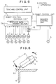
- Fig. 5 is a block diagram to shown an embodiment of a control apparatus for the control robot shown in Fig. 1.
- a control apparatus 5 for the grinder robot 1 comprises a robot control unit 8 comprising a teaching control unit 6 and a robot position deciding unit 7, and a grinder control unit 9.
- the robot control unit 8 obtains instruction data at the teaching control unit 6, then drives servo motors M B , M z , M R , M ⁇ , M ⁇ , M ⁇ , respectively corresponding to each shaft based on teaching data memorised by a teaching data memory section 7A. Moreover, each servo motor is provided with a rotary encoder E for detecting each shaft position. A speed detector is also provided therein.
- a switch circuit 10 is provided between the robot position deciding unit 7 and the servo motor M ⁇ for driving the second shaft ⁇ .
- the switch circuit 10 is constructed so as to connect the servo motor M ⁇ to the robot position deciding unit 7 during teaching, while to the grinder control unit 9 during grinding work.
- the control apparatus 5 can carry out ordinary teaching work by using the six shafts shaft ⁇ , Z, R, ⁇ , ⁇ , ⁇ so as to make the memory section 7A memorise teaching data and reproduce them when necessary.
- the apparatus 5 can carry out torque control as described below by switching the servo M ⁇ to the grinder control unit 9.
- the torque T about the shaft ⁇ shown in Fig. 4 can be controlled to be constant by controlling the current applied to the motor M ⁇ based on a corresponding part of data detected by the six-axes force/torque sensor 3.
- compliance control for generating torque proportional to the deviation on the basis of a predetermined position of the machining point P.
- Fig. 6 shows an explanatory diagram of fettling or surface finishing work.
- this control apparatus can be applied to such fettling or surface finishing work by changing the grindstone 2 into another 2A with a shape suitable for this work.
- the grindstone 2A is formed in a small cylindrical shape, and rotates round the rotation axis x so that the cylinder surface is in contact with an edge portion of the work W to be machined.
- the pressing direction of the grindstone 2A by means of the shaft ⁇ can coincide with a direction in which the machining of the work W can be effected most efficiently.
- the shaft ⁇ can be arranged about an axis different from the rotation axis x. Incidentally, in the same drawing, the proceeding direction of the grindstone 2A is vertical to the drawing paper.
- the orbit of a tool standard point 0' follows an orbit 6 which is substantially parallel to a target shape, and the positions and speeds of the shafts other than the shaft ⁇ are respectively controlled so that the grinder 4 assumes a target posture with respect to the work W. While, with respect to the shaft ⁇ , for example, by carrying out compliance control, the work can be finished not a selected shape. Otherwise, it is also possible to carry out torque control until the posture reaches a suitable angle with respect to a target angle. Thereafter, the torque control is switched to positional control so as not to grind the work excessively.
- the torque control is carried out by one shaft, i.e. the control shaft ⁇ , provided at the distal portion of the robot arm, the inertia and rigidity of the shaft ⁇ are not changed by the posture thereof. Therefore, it is possible to always carry out the torque control under the same conditions. Moreover, since the inertia force caused by the shaft ⁇ is small and the characteristic frequency thereof is high as compared with the three standard shafts, it becomes possible to improve the capacity to respond to the work irrespective of vibration of the other shafts caused by the positional and speed control. Accordingly, the machining work including grinding work can be carried out with high accuracy.
- the six-axis force/torque sensor 3 is used as torque sensor when there is almost no possibility that considerably large force is generated in another direction than the machining direction, it is possible to provide only one torque sensor for detecting the torque of shaft ⁇ . In this case, since only one sensor is provided in the system, the size of robot arm can be much reduced. Moreover, it is also possible to provide the sensor in a joint of the arm. Besides, the cost can be much reduced.
- the torque on machining is directly detected by the torque sensor, it is also possible to indirectly detect the torque by means of the current value of grinder 4, rotation speed of grindstone 2 or current supplied to the driving motor.
- the present invention is applied to the robot cylindrical co-ordinate system with the standard shafts ⁇ , Z, R, however, it is also possible to applied it to a robot using the rectangular co-ordinate system, polar co-ordinate system or multi-joint type.
- control robot which has easy construction, and can control robot work, for example, complex grinding work, with ease.
- a robot of cylindrical co-ordinate system is used.
- the invention is not limited to the robot of this type, and also can be applied to a robot of rectangular co-ordinate type, polar co-ordinate type and multi-joint co-ordinate type.
- the six-shaft force sensor is used as pressing force detection sensor, it is not limited to this type, and it is also possible to use any type of sensor if it can detect pressing force in necessary directions.
- a force control robot which can carry out machining work by pressing the machining tool in the normal direction to the work, and keeping the posture of the machining tool in a constant state against the work by changing the posture thereof without any teachings about the work shaped even if it is initially unknown.
- the pressing force of the machining tool against the work can be suitably controlled by controlling the torque applied to each posture control shaft by moving the machining point of the tool along a fixed machining orbit by reproducing the teaching work.
- the torque control of the posture control shaft referred to here includes torque control used by switching operation together with positional control, or general compliance control or so-called hybrid control.
- a force control robot has also been described which detects pressing force to be applied from a machining tool provided at the distal end of the robot arm to a work to be machined, then controls the detected pressing force to be a target pressing force, in which are provided detection means for detecting counterforce against the pressing force applied to the machining tool, and arithmetical operation means for calculating moment about the center of gravity of the machining tool by apparently shifting a position at which the counterforce is detected by the detection means to the center of gravity of the machining tool so as to calculate the pressing force to be applied from the machining tool to the work.
- the machining tool is pressed against the work in a fixed posture and a fixed direction, moreover, the area where the machining tool contacts with the work is substantially decided.
- the work can be machined with high accuracy by the machining tool based on the pressing force correctly detected.
- the pressing force is detected based on the moment M G about the center gravity of the machining tool, the weight compensation for the machining tool is unnecessary even when the posture of robot is variously changed.
- a force control robot has also been described which detects pressing force to be applied from a machining tool provided at the distal end of the robot arm to a work to be machined, then controls the detected pressing force to be target pressing force, in which are provided detection means for detecting counterforce of the pressing force of the machining tool, and compensation means for obtaining moment about the center of gravity of the machining tool from the detection result of the detection means and further obtaining counter force of the pressing force from the moment so as to compensate the detection result.
- the compensation means arranges both of the position of the center of gravity in the machining tool and the detection position thereof to be the same by attaching a counterweight to the machining tool.
- the detection result can be compensated by the compensation means based on the pressing force applied from the machining tool to the work.
- the detected pressing force of the machining tool can be compensated.
- control apparatus for controlling a force control robot, which detects pressing force to be applied from a machining tool provided at the distal end of the robot arm to a work to be machined, then controls the detected pressing force to be taget pressing force.
- the control apparatus includes detection means for detecting counterforce of the pressing force of the machining tool, posture change means for changing the posture of the machine tool so as not to change the detection result from a predetermined value, and driving means for pressing and moving the machining tool in the direction along which the tool is fixed.
- the center of rotation of the posture control for the machining tool is positioned in the vicinity of the contact point between the machining tool and the work to be machined.
- the posture of the machining tool is changed by the posture change means so as not to change the detection result of the detection means from a predetermined value.
- the machining tool is pressed and moved by the driving means in the direction along which the machining tool is fixed.
- the posture control is carried out round the contact portion.
- the apparatus includes first shape memory means for memorizing the shape of the work from the movement orbit of the machining tool, second shape memory means for memorizing the finished shape of the work, and operation means for carrying out arithmetical operation of a target position and a target posture of the machining tool based on the shapes memorized in both of the first and the second shape memory means.
- a shape of the work to be machined is memorized in the first shape memory means based on the movement orbit of the machining tool. While, a finished shape of the work is memorized in the second shape memory means. Moreover, a target position and a target posture are obtained by means of the operation means based on the shapes which memorized in both of the first and the second shape memory means.
- the pressing or moving direction of the machining tool and its posture to the work are approximately decided.
- the pressing direction is a normal of the work
- the moving direction is a tangent thereof.
- the pitch angle is 20 to 30° and the roll angle is 90° .
- the operational direction and posture of the force control robot are controlled by the above-mentioned force control apparatus.
- this control robot is controlled by the force control apparatus in which the pressing and the moving direction of the machining tool are not determined based on the work, but are determined based on the machining tool itself.
- the robot is so controlled that the machining tool is moved along the surface of the work by moving the tool in a predermined pressing direction, further by moving it in the vertical direction to the pressing force.
- the above means is insufficient to carry out the control operation for intentionally changing the posture of the machining tool so as to keep it in a constant state with respect to the work whose shape is not known.
- the pressing direction is not in accordance with the normal direction of the work, and the machining tool is always moved in a predetermined pressing direction and is also moved in the vertical direction to the pressing direction, the pressing force and the moment generated thereby are largely changed as compared with the case in which the pressing direction coincides with the normal direction. In contrast, where the pressing direction coincides with the normal, the pressing force and the moment caused thereby are not changed so largely.
- the pressing direction can be arranged to coincide with the normal of the work.
- the posture of the machining tool can be changed so as not to generate the change of the pressing force or the like, even though the surface of the work is curved three-dimensionally, the posture of the machining tool to the work can be kept in a constant state. Therefore, the machining tool can be moved in accordance with the surface shape of the work with being kept pressed with a predetermined force against the work even when the shape thereof is not known.
Landscapes
- Engineering & Computer Science (AREA)
- Mechanical Engineering (AREA)
- Robotics (AREA)
- Manipulator (AREA)
- Finish Polishing, Edge Sharpening, And Grinding By Specific Grinding Devices (AREA)
Claims (4)
- Steuerroboter (1), welcher umfaßt:
einen Roboterarm, angebracht zur Bewegung um dreidimensionale Koordinaten (Z,R,θ);
eine Bearbeitungsanordnung (4), die daran angebracht ist, wobei die Bearbeitungsanordnung ein drehbares Werkzeug (2) zum Schleifen am entfernten Ende des Roboterarms beinhaltet, um somit eine Schleifarbeit auszuführen durch Drücken des Werkzeuges (2) gegen die Oberfläche eines Werkstückes, das zu bearbeiten ist, mit einer vorbestimmten Druckkraft;
eine Haltungssteuerungswelle, die sich axial zum Roboterarm erstreckt, zum Steuern der Winkelhaltung β des Bearbeitungswerkzeuges (4) um die Achse des Roboterarms; und
wobei die Drehwelle des drehbaren Werkzeugs (2) ihre Drehachse senkrecht angeordnet hat zur Achse der Haltungssteuerungswelle,
dadurch gekennzeichnet, daß
das Werkzeug ein Schleifrad (2) ist, das so am Roboter angebracht ist, daß seine Drehachse beabstandet ist von der Achse der Haltungssteuerungswelle unter einem Abstand, der größer ist als der Radius des Schleifrades, und so daß das Schleifrad einen Abstand hat von einer Ebene, die senkrecht ist zu seiner Drehachse und die Achse der Haltungssteuerungswelle enthält; und
das Drehmoment T der Haltungssteuerungswelle, die Druckkraft F des drehbaren Werkzeuges und der Abstand r von der Achse der Haltungssteuerungswelle zum Bearbeitungspunkt des Werkzeuges so sind, das
- Steuerroboter nach Anspruch 1, gekennzeichnet durch:
eine Antriebssteuereinrichtung für die Haltungssteuerungswelle;
eine Robotersteuervorrichtung, die Lehrdaten hält bezüglich der Robotersteuerungswellen einschließlich der Haltungssteuerungswelle und die Robotersteuerungswellen in Übereinstimmung mit den Lehrdaten steuert;
eine Schleifersteuervorrichtung zum Steuern der Druckkraft des drehbaren Werkzeuges durch Antreiben der Haltungssteuerungswelle zur Schleifbearbeitung; und
eine Schalteinrichtung zum Schalten der Antriebssteuereinrichtung von der Robotersteuereinrichtung zur Schleifersteuervorrichtung zur Schleifbearbeitung. - Steuerroboter nach Anspruch 2, dadurch gekennzeichnet, daß die Robotersteuervorrichtung und die Schleifersteuervorrichtung jeweils die Robotersteuerungswellen durch Reproduzieren der Lehrdaten steuern und den Bearbeitungspunkt des drehbaren Werkzeuges entlang einer vorbstimmten Bearbeitungsbahn bewegen, um somit eine Schleifbearbeitung auszuführen unter Drücken des drehbaren Werkzeuges gegen das Werkstück unter geeigneter Drehmomentssteuerung der Haltungssteuerungswelle.
- Steuerroboter nach Anspruch 3, dadurch gekennzeichnet, daß die Robotersteuervorrichtung eine Lehrsteuerdisk umfaßt zum Eingeben von Lehrdaten, einen Lehrdaten-Speicherabschnitt zum Speichern der Lehrdaten und eine Roboterpositions-Entscheidungseinheit zum Entscheiden der Position des drehbaren Werkzeuges in Übereinstimmung mit den Lehrdaten, die durch den Lehrdatenspeicherabschnitt gespeichert sind.
Priority Applications (1)
| Application Number | Priority Date | Filing Date | Title |
|---|---|---|---|
| EP93117614A EP0584843B1 (de) | 1990-02-27 | 1991-02-27 | Vorrichtung zum Steuern der Bearbeitungskraft eines Werkzeugs |
Applications Claiming Priority (6)
| Application Number | Priority Date | Filing Date | Title |
|---|---|---|---|
| JP44550/90 | 1990-02-27 | ||
| JP4455090A JP2911160B2 (ja) | 1990-02-27 | 1990-02-27 | グラインダロボット |
| JP14749790 | 1990-06-07 | ||
| JP147497/90 | 1990-06-07 | ||
| JP26960090A JP3217351B2 (ja) | 1990-06-07 | 1990-10-09 | 力制御装置及びそれを用いたロボット |
| JP269600/90 | 1990-10-09 |
Related Child Applications (2)
| Application Number | Title | Priority Date | Filing Date |
|---|---|---|---|
| EP93117614.3 Division-Into | 1991-02-27 | ||
| EP93117614A Division EP0584843B1 (de) | 1990-02-27 | 1991-02-27 | Vorrichtung zum Steuern der Bearbeitungskraft eines Werkzeugs |
Publications (2)
| Publication Number | Publication Date |
|---|---|
| EP0444657A1 EP0444657A1 (de) | 1991-09-04 |
| EP0444657B1 true EP0444657B1 (de) | 1996-02-07 |
Family
ID=27291944
Family Applications (2)
| Application Number | Title | Priority Date | Filing Date |
|---|---|---|---|
| EP91102976A Expired - Lifetime EP0444657B1 (de) | 1990-02-27 | 1991-02-27 | Robotersteuerung |
| EP93117614A Expired - Lifetime EP0584843B1 (de) | 1990-02-27 | 1991-02-27 | Vorrichtung zum Steuern der Bearbeitungskraft eines Werkzeugs |
Family Applications After (1)
| Application Number | Title | Priority Date | Filing Date |
|---|---|---|---|
| EP93117614A Expired - Lifetime EP0584843B1 (de) | 1990-02-27 | 1991-02-27 | Vorrichtung zum Steuern der Bearbeitungskraft eines Werkzeugs |
Country Status (4)
| Country | Link |
|---|---|
| US (2) | US5265195A (de) |
| EP (2) | EP0444657B1 (de) |
| KR (1) | KR940003204B1 (de) |
| DE (2) | DE69116901T2 (de) |
Families Citing this family (62)
| Publication number | Priority date | Publication date | Assignee | Title |
|---|---|---|---|---|
| JPH04310384A (ja) * | 1991-04-09 | 1992-11-02 | Toyota Motor Corp | 複腕ロボット |
| JPH05185387A (ja) * | 1992-01-14 | 1993-07-27 | Mitsubishi Electric Corp | ロボットの制御装置 |
| JP3167404B2 (ja) * | 1992-02-26 | 2001-05-21 | 本田技研工業株式会社 | ロボットの関節駆動制御装置 |
| US5565749A (en) * | 1993-04-28 | 1996-10-15 | Kabushiki Kaisha Toshiba | Method of controlling a grinder robot |
| JPH07319547A (ja) * | 1994-05-20 | 1995-12-08 | Fanuc Ltd | ロボットの倣い制御方法 |
| KR100449429B1 (ko) * | 1995-09-14 | 2004-12-13 | 가부시키가이샤 야스가와덴끼 | 로봇의교시장치 |
| KR0176662B1 (ko) * | 1995-12-28 | 1999-04-01 | 김광호 | 칩마운터용 직교로봇의 칩마운팅 위치제어방법 및 위치제어장치 |
| JP2977772B2 (ja) * | 1996-10-08 | 1999-11-15 | 川崎重工業株式会社 | 押付け加工装置 |
| JP3694573B2 (ja) * | 1997-03-10 | 2005-09-14 | ファナック株式会社 | プレス機械におけるモータトルク制御方法及びプレス機械 |
| IL120889A (en) * | 1997-05-22 | 1998-10-30 | Eshed Robotec 1982 Ltd | Method and facility for direct learning of vending machines |
| KR100526855B1 (ko) * | 1998-01-22 | 2005-11-08 | 닛다 가부시키가이샤 | 그라인더 가압장치 |
| SE9800984D0 (sv) * | 1998-03-24 | 1998-03-24 | Thordab Ab | Bearbetningsmaskin |
| US6249991B1 (en) * | 1999-03-17 | 2001-06-26 | National Optronics, Incorporated | Control system for eyeglass tracer |
| US6264534B1 (en) * | 1999-03-25 | 2001-07-24 | Ford Global Technologies, Inc. | Method and tooling for automated wet or dry sanding of a vehicle surface |
| DE19943318A1 (de) * | 1999-09-10 | 2001-03-22 | Charalambos Tassakos | Verfahren und Vorrichtung zum Erfassen der Position von Bahnpunkten einer Trajektorie |
| US6585561B2 (en) * | 2000-04-07 | 2003-07-01 | Kabushiki Kaisha Koyama | Method of teaching position |
| DE10058123A1 (de) * | 2000-11-22 | 2002-05-23 | Wella Ag | Deckenstativeinheit |
| US6456901B1 (en) * | 2001-04-20 | 2002-09-24 | Univ Michigan | Hybrid robot motion task level control system |
| US20030132726A1 (en) * | 2001-10-16 | 2003-07-17 | Dohring Mark E. | Admittance enhancement in force feedback of dynamic systems |
| US7118452B2 (en) * | 2004-02-12 | 2006-10-10 | The Boeing Company | Pneumatically actuated flexible coupling end effectors for lapping/polishing |
| WO2007099626A1 (ja) * | 2006-03-01 | 2007-09-07 | Fujitsu Limited | トルク測定装置 |
| DE102006022831A1 (de) * | 2006-05-16 | 2007-11-22 | Siemens Ag | Verfahren zum Steuern einer Schleifmaschine und numerisch gesteuerte Schleifmaschine |
| US8104387B2 (en) * | 2006-08-11 | 2012-01-31 | Alstom Technology Ltd | Tube stub removal apparatus |
| EP2064603B1 (de) * | 2006-09-22 | 2013-01-09 | Agop Jean Georges Apkarian | Vorrichtung, system und computerprogramm zur steuerung eines werkzeugs |
| DE102006049956A1 (de) * | 2006-10-19 | 2008-04-24 | Abb Ag | System und Verfahren zur automatisierten Ver- und/oder Bearbeitung von Werkstücken |
| JP4267027B2 (ja) * | 2006-12-07 | 2009-05-27 | ファナック株式会社 | ロボット制御装置 |
| DE102006061752A1 (de) * | 2006-12-28 | 2008-07-03 | Kuka Roboter Gmbh | Roboter und Verfahren zum Programmieren eines Roboters |
| JP5260139B2 (ja) * | 2008-05-22 | 2013-08-14 | 株式会社日進製作所 | 砥石接触感知方法およびその装置、ならびにホーニング加工方法およびホーニング盤 |
| ATE516915T1 (de) * | 2009-05-19 | 2011-08-15 | Teng-Hung Wang | Einstellbarer werkzeughilfsmechanismus für eine werkzeugmaschine |
| EP2465016A1 (de) * | 2009-08-14 | 2012-06-20 | ABB Technology AG | Industrieroboter und verfahren zur einstellung eines roboterprogramms |
| DE102009040194B4 (de) * | 2009-09-07 | 2015-06-18 | Deutsches Zentrum für Luft- und Raumfahrt e.V. | Verfahren zur Kraftregelung |
| DE102011006679B4 (de) * | 2011-03-16 | 2018-07-12 | Ferrobotics Compliant Robot Technology Gmbh | Aktive Handhabungsvorrichtung und Verfahren für Kontaktaufgaben |
| EP2760630A4 (de) * | 2011-09-22 | 2015-06-03 | Skf Ab | Prozessinterne kompensation von bearbeitungsvorgängen und maschinenanordnung |
| US20130273818A1 (en) * | 2012-04-13 | 2013-10-17 | Hon Hai Precision Industry Co., Ltd. | Manipulator and polishing mechanism thereof |
| DE102012206503B4 (de) * | 2012-04-19 | 2015-10-15 | Deutsches Zentrum für Luft- und Raumfahrt e.V. | Verfahren zur Kraftregelung |
| WO2014043702A1 (en) * | 2012-09-17 | 2014-03-20 | Rethink Robotics, Inc. | Constraining robotic manipulators with redundant degrees of freedom |
| FR3018618B1 (fr) * | 2014-03-11 | 2017-09-22 | Univ Nantes | Procede et systeme de controle d'un poncage orbital |
| CN103991797B (zh) * | 2014-05-13 | 2017-04-26 | 国家电网公司 | 一种电力设备码放装置 |
| GB201417861D0 (en) * | 2014-10-09 | 2014-11-26 | Rolls Royce Plc | Abrasive processing method |
| WO2016074169A1 (zh) * | 2014-11-12 | 2016-05-19 | 深圳市大疆创新科技有限公司 | 一种对目标物体的检测方法、检测装置以及机器人 |
| CN104786129A (zh) * | 2015-04-28 | 2015-07-22 | 北京航空航天大学 | 全自动打磨抛光机器人 |
| DK201600053U3 (da) * | 2015-08-12 | 2016-11-25 | Senex As | Slibehoved til et slibearrangement |
| US10449654B2 (en) * | 2015-09-01 | 2019-10-22 | Nanyang Technological University | Instrumented tools for monitoring interaction dynamics during contact task |
| CN105666320A (zh) * | 2016-03-01 | 2016-06-15 | 林中尉 | 可浮动压紧的旋转动力头 |
| US11780099B2 (en) * | 2016-04-07 | 2023-10-10 | Ferrobotics Compliant Robot Technology Gmbh | Robot-aided grinding apparatus |
| CN105835070B (zh) * | 2016-06-08 | 2018-11-02 | 江门市鸿业机械厂有限公司 | 大扭矩机械手加工中心 |
| US10350754B2 (en) * | 2016-09-27 | 2019-07-16 | Denso Wave Incorporated | Control device for robot |
| JP7314475B2 (ja) * | 2016-11-11 | 2023-07-26 | セイコーエプソン株式会社 | ロボット制御装置、及び、ロボット制御方法 |
| WO2019052971A1 (de) * | 2017-09-15 | 2019-03-21 | Inventio Ag | Vorrichtung und verfahren zum automatisierten durchführen eines montageschritts in einem aufzugschacht |
| JP2019155542A (ja) * | 2018-03-14 | 2019-09-19 | 株式会社東芝 | 搬送装置、搬送システム、コントローラ、および搬送方法 |
| WO2019238940A1 (en) * | 2018-06-15 | 2019-12-19 | Universal Robots A/S | Estimation of payload attached to a robot arm |
| US11633832B2 (en) * | 2018-11-30 | 2023-04-25 | The Boeing Company | Systems and methods for sanding a surface of a structure |
| CN109773588B (zh) * | 2019-03-01 | 2021-03-02 | 山东大学 | 一种机床数字孪生模型性能测试方法及装置 |
| EP4054801A4 (de) * | 2019-11-07 | 2023-08-23 | Mirka Ltd | Verfahren zum steuern des betriebs eines schleifsystems und vorrichtung mit einem schleifkopf |
| WO2021094055A1 (de) * | 2019-11-12 | 2021-05-20 | Kistler Holding Ag | Zerspanungsmaschine mit einem kraftaufnehmer, verfahren zum betrieb einer solchen zerspanungsmaschine sowie verfahren zum kalibrieren des kraftaufnehmers einer solchen zerspanungsmaschine |
| DK180673B1 (en) * | 2019-12-29 | 2021-11-25 | Universal Robots As | Method of obtaining vibrational properties of robot arm |
| CN112139944B (zh) * | 2020-09-25 | 2021-09-17 | 安徽新境界自动化技术有限公司 | 一种双机械臂机器人柔性打磨装置 |
| CN114559560A (zh) * | 2020-11-27 | 2022-05-31 | 广东博智林机器人有限公司 | 打孔作业控制方法、装置和协作机器人 |
| DE102021100314A1 (de) * | 2021-01-11 | 2022-07-14 | Aktiebolaget Skf | Bearbeitungseinheit und Verfahren zum Bearbeiten eines Bauteils |
| CN114800500B (zh) * | 2022-04-21 | 2023-03-24 | 无锡斯帝尔科技有限公司 | 一种用于打磨机器人的柔性恒力控制方法及系统 |
| CN115338739A (zh) * | 2022-08-24 | 2022-11-15 | 深圳学泰科技有限公司 | 一种基于运动学的机械加工打磨工业机器人 |
| CN116673874A (zh) * | 2023-06-21 | 2023-09-01 | 上海赛威德机器人有限公司 | 一种液压恒力磨抛控制方法及系统 |
Family Cites Families (31)
| Publication number | Priority date | Publication date | Assignee | Title |
|---|---|---|---|---|
| JPS5016551B1 (de) * | 1970-12-19 | 1975-06-13 | ||
| DE2204581B2 (de) * | 1972-02-01 | 1977-12-08 | Wolters, Peter, 4020 Mettmann | Steuereinrichtung fuer den bearbeitungsdruck einer laepp- oder honmaschine |
| US3877180A (en) * | 1973-11-12 | 1975-04-15 | Univ Carnegie Mellon | Drive systems for a grinding wheel |
| US4014142A (en) * | 1974-01-16 | 1977-03-29 | Norton Company | Method and apparatus for grinding at a constant metal removal rate |
| US4068156A (en) * | 1977-03-01 | 1978-01-10 | Martin Marietta Corporation | Rate control system for manipulator arms |
| US4186529A (en) * | 1977-06-28 | 1980-02-05 | S. E. Huffman Corporation | Programmably controlled method for grinding end cutting tools and the like |
| US4115956A (en) * | 1977-06-28 | 1978-09-26 | S. E. Huffman Corporation | Programmably controlled machine for grinding end cutting tools and the like |
| US4249062A (en) * | 1978-03-09 | 1981-02-03 | Shin Meiwa Industry Co., Ltd. | Apparatus and method for sensing welding point in automatic welding apparatus |
| DE2950881C2 (de) * | 1979-12-18 | 1983-06-01 | Fa. Peter Wolters, 2370 Rendsburg | Steuereinrichtung für den Bearbeitungsdruck an Läpp-, Hon- und Schleißmaschinen |
| IT1129409B (it) * | 1980-03-07 | 1986-06-04 | Fiat Ricerche | Trasduttore a sei gradi di liberta per convertire in segnali elettrici le forze ed i momenti applicati ad un organo mobile particolarmente al braccio mobile di un robot |
| IT1144708B (it) * | 1981-05-15 | 1986-10-29 | Dea Spa | Sistema di produzione industriale servito da una pluralita di bracci operativi e controllato da un sistema a calcolatore |
| JPS58126090A (ja) * | 1982-01-18 | 1983-07-27 | 株式会社神戸製鋼所 | 多関節腕機構 |
| US4523049A (en) * | 1984-04-16 | 1985-06-11 | Atlantic Richfield Company | Methane conversion process |
| JPS6052296A (ja) * | 1983-09-02 | 1985-03-25 | 株式会社日立製作所 | 力センサ出力の修正方法 |
| EP0142072A3 (de) * | 1983-11-15 | 1986-12-30 | Aida Engineering Ltd. | Schleifroboter |
| AU3583084A (en) * | 1983-12-10 | 1985-06-13 | Aida Engineering Ltd. | Playback grinding robot |
| JPS6165762A (ja) * | 1984-09-06 | 1986-04-04 | Nippon Sheet Glass Co Ltd | 板状体の端面研磨装置 |
| DE3520521A1 (de) * | 1985-06-07 | 1986-12-11 | Montanwerke Walter GmbH, 7400 Tübingen | Maschine zum spanenden einarbeiten der spanraumnuten von laenglichen, am umfang schneidenden werkzeugen mit halbkugelfoermigem ende |
| IT1185800B (it) * | 1985-06-11 | 1987-11-18 | D B A Spa | Dispositivo per effettuare automaticamente il cambio dell utensile di misura in un macchina o in un robot di misura |
| US4680519A (en) * | 1985-09-23 | 1987-07-14 | General Electric Co. | Recursive methods for world-to-joint transformation for a robot manipulator |
| JPS63300889A (ja) * | 1987-05-29 | 1988-12-08 | 旭硝子株式会社 | 曲板の周縁処理用メカニカルハンド |
| JPS63318277A (ja) * | 1987-06-19 | 1988-12-27 | ファナック株式会社 | 水平ア−ム型多関節ロボットの上下軸直接教示方法と装置 |
| DE3826277A1 (de) * | 1987-08-04 | 1989-02-16 | Yamazaki Mazak Corp | Werkzeugmaschine mit einer schleiffunktion, umfassend eine elektroerosionsaus-/zurichtvorrichtung, ein schleifwerkzeug und eine spansammelvorrichtung |
| JP2707087B2 (ja) * | 1987-09-09 | 1998-01-28 | ファナック株式会社 | ロボット制御装置 |
| EP0331265B1 (de) * | 1988-03-01 | 1995-08-23 | Hitachi Construction Machinery Co., Ltd. | Positions-/Kraft-Steuerungsgerät für Werkzeugmaschinen mit mehreren Freiheitsgraden |
| JPH01234141A (ja) * | 1988-03-16 | 1989-09-19 | Nitta Ind Corp | 工具の慣性による影響を除去する方法および装置 |
| DE3836003A1 (de) * | 1988-10-21 | 1990-04-26 | Wolfgang Prof Dr Ing Ziegler | Verfahren und vorrichtung zur durchfuehrung einer kraftgeregelten bewegung |
| FR2639572A1 (fr) * | 1988-11-29 | 1990-06-01 | Renault | Robot multiaxes |
| US5067085A (en) * | 1989-05-15 | 1991-11-19 | Southwest Research Institute | Optical robotic canopy polishing system |
| JPH04210365A (ja) * | 1990-11-30 | 1992-07-31 | Komatsu Ltd | 回転研削工具の押付力制御装置 |
| EP0492014B1 (de) * | 1990-12-28 | 1996-03-20 | Aiko Engineering Co. Ltd. | Automatische Schleifvorrichtung |
-
1991
- 1991-02-27 DE DE69116901T patent/DE69116901T2/de not_active Expired - Fee Related
- 1991-02-27 EP EP91102976A patent/EP0444657B1/de not_active Expired - Lifetime
- 1991-02-27 EP EP93117614A patent/EP0584843B1/de not_active Expired - Lifetime
- 1991-02-27 US US07/661,309 patent/US5265195A/en not_active Expired - Lifetime
- 1991-02-27 KR KR1019910003234A patent/KR940003204B1/ko not_active Expired - Fee Related
- 1991-02-27 DE DE69130397T patent/DE69130397T2/de not_active Expired - Fee Related
-
1993
- 1993-04-20 US US08/049,426 patent/US5509847A/en not_active Expired - Lifetime
Also Published As
| Publication number | Publication date |
|---|---|
| EP0584843A3 (de) | 1994-05-04 |
| EP0584843A2 (de) | 1994-03-02 |
| DE69116901D1 (de) | 1996-03-21 |
| US5265195A (en) | 1993-11-23 |
| KR940003204B1 (ko) | 1994-04-16 |
| DE69130397T2 (de) | 1999-04-15 |
| EP0444657A1 (de) | 1991-09-04 |
| US5509847A (en) | 1996-04-23 |
| DE69116901T2 (de) | 1996-07-18 |
| KR910021291A (ko) | 1991-12-20 |
| DE69130397D1 (de) | 1998-11-26 |
| EP0584843B1 (de) | 1998-10-21 |
Similar Documents
| Publication | Publication Date | Title |
|---|---|---|
| EP0444657B1 (de) | Robotersteuerung | |
| CN101195221B (zh) | 进行力控制的机器人控制装置 | |
| JP2676793B2 (ja) | 倣い制御ロボット | |
| JP6778050B2 (ja) | 工作機械 | |
| KR102838341B1 (ko) | 표면들의 로봇-보조 기계가공을 위한 장치 | |
| KR102642762B1 (ko) | 로봇-보조 연마에 있어서 회전 속도 제어 | |
| JPH074765B2 (ja) | 曲面加工装置 | |
| JPH0413062B2 (de) | ||
| JP2022536300A (ja) | ロボット支援表面加工における位置決め誤差の補正 | |
| WO2021075031A1 (ja) | 多関節ロボット | |
| CN113319687A (zh) | 控制机床中的接触力 | |
| JPH0438553B2 (de) | ||
| JPH05108123A (ja) | ツール先端位置補正方法 | |
| JP2536338B2 (ja) | ロボットの被加工物把持機構 | |
| JP3217351B2 (ja) | 力制御装置及びそれを用いたロボット | |
| JP2911160B2 (ja) | グラインダロボット | |
| JPH10109285A (ja) | マニプレータ | |
| JPH0756127Y2 (ja) | ウィービング動作をするアーク溶接ロボット | |
| CN214080883U (zh) | 一种自适应式抛磨装置 | |
| JPH1158285A (ja) | ハンド機構の力制御システム | |
| JP2791478B2 (ja) | 水研ロボット | |
| JPH106180A (ja) | ワーク加工装置 | |
| JP2597508B2 (ja) | 球面作業ロボット | |
| TWI765616B (zh) | 具伺服驅動功能的浮動研磨系統 | |
| JP2000127018A (ja) | 回転駆動型工具及びそれを用いた加工装置 |
Legal Events
| Date | Code | Title | Description |
|---|---|---|---|
| PUAI | Public reference made under article 153(3) epc to a published international application that has entered the european phase |
Free format text: ORIGINAL CODE: 0009012 |
|
| 17P | Request for examination filed |
Effective date: 19910227 |
|
| AK | Designated contracting states |
Kind code of ref document: A1 Designated state(s): DE FR GB SE |
|
| 17Q | First examination report despatched |
Effective date: 19930621 |
|
| RBV | Designated contracting states (corrected) | ||
| GRAA | (expected) grant |
Free format text: ORIGINAL CODE: 0009210 |
|
| AK | Designated contracting states |
Kind code of ref document: B1 Designated state(s): DE |
|
| XX | Miscellaneous (additional remarks) |
Free format text: TEILANMELDUNG 93117614.3 EINGEREICHT AM 27/02/91. |
|
| REF | Corresponds to: |
Ref document number: 69116901 Country of ref document: DE Date of ref document: 19960321 |
|
| PLBE | No opposition filed within time limit |
Free format text: ORIGINAL CODE: 0009261 |
|
| STAA | Information on the status of an ep patent application or granted ep patent |
Free format text: STATUS: NO OPPOSITION FILED WITHIN TIME LIMIT |
|
| 26N | No opposition filed | ||
| PGFP | Annual fee paid to national office [announced via postgrant information from national office to epo] |
Ref country code: DE Payment date: 20080221 Year of fee payment: 18 |
|
| PG25 | Lapsed in a contracting state [announced via postgrant information from national office to epo] |
Ref country code: DE Free format text: LAPSE BECAUSE OF NON-PAYMENT OF DUE FEES Effective date: 20090901 |