EP0445009B1 - Frequenzabstimmbare Hochfrequenzröhre - Google Patents
Frequenzabstimmbare Hochfrequenzröhre Download PDFInfo
- Publication number
- EP0445009B1 EP0445009B1 EP19910400485 EP91400485A EP0445009B1 EP 0445009 B1 EP0445009 B1 EP 0445009B1 EP 19910400485 EP19910400485 EP 19910400485 EP 91400485 A EP91400485 A EP 91400485A EP 0445009 B1 EP0445009 B1 EP 0445009B1
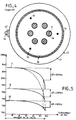
- Authority
- EP
- European Patent Office
- Prior art keywords
- rod
- cavity
- rods
- microwave tube
- axis
- Prior art date
- Legal status (The legal status is an assumption and is not a legal conclusion. Google has not performed a legal analysis and makes no representation as to the accuracy of the status listed.)
- Expired - Lifetime
Links
- 238000010894 electron beam technology Methods 0.000 claims description 24
- 230000007246 mechanism Effects 0.000 claims description 13
- 230000005540 biological transmission Effects 0.000 claims description 10
- FRWYFWZENXDZMU-UHFFFAOYSA-N 2-iodoquinoline Chemical compound C1=CC=CC2=NC(I)=CC=C21 FRWYFWZENXDZMU-UHFFFAOYSA-N 0.000 claims description 4
- RYGMFSIKBFXOCR-UHFFFAOYSA-N Copper Chemical compound [Cu] RYGMFSIKBFXOCR-UHFFFAOYSA-N 0.000 claims description 4
- PNEYBMLMFCGWSK-UHFFFAOYSA-N aluminium oxide Inorganic materials [O-2].[O-2].[O-2].[Al+3].[Al+3] PNEYBMLMFCGWSK-UHFFFAOYSA-N 0.000 claims description 4
- LTPBRCUWZOMYOC-UHFFFAOYSA-N beryllium oxide Inorganic materials O=[Be] LTPBRCUWZOMYOC-UHFFFAOYSA-N 0.000 claims description 4
- 229910052802 copper Inorganic materials 0.000 claims description 4
- 239000010949 copper Substances 0.000 claims description 4
- 239000003989 dielectric material Substances 0.000 claims description 4
- 229910052751 metal Inorganic materials 0.000 claims description 4
- 239000002184 metal Substances 0.000 claims description 4
- 230000000149 penetrating effect Effects 0.000 claims description 2
- 230000003993 interaction Effects 0.000 description 10
- 230000005684 electric field Effects 0.000 description 7
- 238000005259 measurement Methods 0.000 description 5
- 239000012528 membrane Substances 0.000 description 5
- 230000008901 benefit Effects 0.000 description 3
- 230000001939 inductive effect Effects 0.000 description 3
- 230000003071 parasitic effect Effects 0.000 description 3
- 230000007423 decrease Effects 0.000 description 2
- 239000000463 material Substances 0.000 description 2
- 230000010355 oscillation Effects 0.000 description 2
- 230000001133 acceleration Effects 0.000 description 1
- 238000005219 brazing Methods 0.000 description 1
- 230000008859 change Effects 0.000 description 1
- 230000008094 contradictory effect Effects 0.000 description 1
- 230000008878 coupling Effects 0.000 description 1
- 238000010168 coupling process Methods 0.000 description 1
- 238000005859 coupling reaction Methods 0.000 description 1
- 238000006073 displacement reaction Methods 0.000 description 1
- 230000000694 effects Effects 0.000 description 1
- 230000004907 flux Effects 0.000 description 1
- 238000011084 recovery Methods 0.000 description 1
- 238000010025 steaming Methods 0.000 description 1
- 238000003466 welding Methods 0.000 description 1
Images



Classifications
-
- H—ELECTRICITY
- H01—ELECTRIC ELEMENTS
- H01J—ELECTRIC DISCHARGE TUBES OR DISCHARGE LAMPS
- H01J23/00—Details of transit-time tubes of the types covered by group H01J25/00
- H01J23/16—Circuit elements, having distributed capacitance and inductance, structurally associated with the tube and interacting with the discharge
- H01J23/18—Resonators
- H01J23/20—Cavity resonators; Adjustment or tuning thereof
- H01J23/207—Tuning of single resonator
Definitions
- the present invention relates to microwave tubes with longitudinal electron beams passing through at least one frequency tunable cavity. It applies more particularly to klystrons whether they are single-beam or multi-beam.
- a single-beam klystron is built around an axis. It mainly comprises an electron gun which produces a longitudinal electron beam. This beam passes through successive cavities and sliding tubes. A sliding tube connects two successive cavities. The cavities are used to modulate the speed of the electrons. The electron beam is collected in a collector which is arranged in the extension of the last cavity. A focusing device surrounds the cavities. It prevents the electron beam from diverging.
- the frequency matching of the cavities of a klystron is necessary to optimize the performance of the tube at the time of the tests. Indeed, a certain number of parameters of the tube depend on the frequency offsets of the cavities with respect to each other and on the operating frequency of the tube.
- the electron beam, the microwave energy output device etc ... are not strictly identical to those initially planned, and a variation of the resonance frequencies of the cavities allows a certain catching up.
- the tube is provided with a system for adjusting, on site, the resonant frequency of its cavities.
- Multibeam klystrons are well known in the prior art and French patents No. 992,853, No. 2,596,198 and No. 2,596,199 describe them.
- a multibeam klystron can be produced by placing several electron guns on a crown centered on an axis. These guns produce elementary beams parallel to this axis. The elementary beams pass through successive cavities, separated by sliding tubes. Each cavity is crossed by all the elementary beams. The beams can be collected in a common collector. The focusing device can also be common to all the beams.
- Multibeam klystrons are developing more and more because they make it possible to obtain a compact, high-efficiency tube while using a low accelerating voltage.
- the klystron cavities are generally simple in shape. They are often cylindrical or parallelepipedic. They have on two opposite walls, orifices also facing each other, to allow the electron beams to pass.
- the sliding tubes which connect two successive cavities have their ends which penetrate into the cavities through these orifices. They then create protrusions inside the cavities. The space between two opposite protrusions forms the interaction space.
- the resonant frequency of a cavity is proportional to the product: (LC) - 1 ⁇ 2 .
- L and C represent respectively the self and the equivalent capacity of the cavity. These parameters are a function of the geometry of the cavity.
- a inductive tuning device modifies the position of one or more walls of the cavity.
- a piston and membrane device is used which deforms a side wall of the cavity, substantially parallel to the axis of the tube. This device is activated from outside the tube thanks to a control mechanism and this mechanism is quite bulky.
- a focusing device surrounds the cavities. It is composed of a set of coils. In order not to increase either the volume of the tube or its weight, it is arranged so that the focusing device is very close to the side wall of the cavities. The space is reduced to insert the control mechanism of the piston and diaphragm tuning device, between the cavities and the focusing device.
- the cavities of multibeam klystrons are generally cylindrical and their diameter is much greater than their height.
- the beams are arranged on a circle of small diameter compared to that of the cavity, to create in the central region of the cavity, a strong electric field. If you do not want to use a too bulky tuning device, it only acts on a small portion of the side wall and then has little influence on the volume of the cavity.
- the interaction space between two sliding tubes is varied opposite or else a capacitance is created by means of a pallet which is approached or that the 'we move away from a sliding tube.
- the pallet is actuated from the outside of the tube and it is moved transversely to the axis of the tube.
- US Pat. No. 2,500,944 discloses a multibeam tube with a rod tuning device which plunges into a cavity parallel to the axis of the beams. This rod is located between the electron beams.
- the present invention aims to remedy these drawbacks by proposing a microwave tube with at least one frequency tunable cavity.
- the frequency tuning device does not disturb the operation of the tube and does not increase either the volume or the weight of the tube.
- the present invention provides a microwave tube as claimed in claim 1.
- the tuning device may include one or more rods.
- the number of rods is equal to the number of electron beams or either to a submultiple, or to a multiple of the number of electron beams.
- the end of a rod, inside the cavity will be rounded.
- when there are several rods they will be distributed regularly on a circle centered on the axis XX ', this circle surrounding the electron beam (s).
- the rods and / or the crown can be made of metal, copper, for example
- the rods and / or the crown may be made of a dielectric material, of alumina or of beryllium oxide, for example.
- FIG. 1 represents a cavity provided with an inductive tuning device.
- This cavity belongs to a single-beam klystron built around an axis XX ′. It is assumed that the cavity has the shape of a rectangular parallelepiped with two opposite walls 1 transverse to the axis XX ′ and four opposite walls 2 opposite in pairs, parallel to the axis XX ′.
- the electron beam 5 passes right through the cavity.
- the two transverse walls 1 are each provided with a sliding tube 3.
- the sliding tubes are opposite and they each form a protuberance inside the cavity.
- a focusing device 8 composed of a set of coils, surrounds the cavities of the klystron.
- the coils are placed as close as possible to the walls 2 of the cavity.
- the tuning device 4 is a tuning device with piston 6 and membrane 7.
- the membrane 7 partially or completely replaces at least one of the walls 2 parallel to the axis XX ′.
- the piston 6 is actuated from the outside of the tube, substantially transversely to the axis XX ′, thanks to an appropriate control mechanism.
- This mechanism is bulky and is placed outside the cavity, between the latter and the focusing device 8.
- the piston in its movement drives the membrane 7.
- the displacement of the membrane 7 makes it possible to increase or decrease the volume of the cavity. As a result, the frequency of the cavity varies.
- a bellows device is provided to maintain the vacuum tightness of the cavity relative to the outside of the tube. This device is not shown.
- This tuning device is ill-suited to the cavities of multibeam klystrons. Indeed, the cavities of a multibeam klystron have large dimensions and the electron beams are grouped in their central part. The deformation of part of the wall of the cavity has little influence on the frequency. For the deformation to be effective, an even more bulky control mechanism would have to be used.
- FIG. 2 represents, in cross section, a cavity 20 provided with a tuning device 25 of a multibeam klystron.
- the cavity is cylindrical.
- the klystron has six electron beams 21 distributed over a circle centered on the axis of the cylinder.
- the beams 21 emerge from a sliding tube 22 while entering the cavity 20 and penetrate into another sliding tube 22 while leaving the cavity 20.
- the circle on which the beams are distributed has a diameter much smaller than that of the cylinder.
- the tuning device 25 is a capacitive pallet tuning device 23.
- Pallet 23 is actuated from outside the tube. It can move away or approach a sliding tube by moving substantially radially.
- a bellows device 24 keeps the interior of the cavity tight.
- the focusing device has not been shown. This tuning device is effective in varying the resonant frequency of the cavity. On the other hand, it disturbs the electric fields in the interaction spaces which are close to it and little or no the electric fields in the spaces distant from it. This disturbance leads to defocusing, oscillations and the appearance of parasitic modes.
- FIG. 3 represents a cavity 30 provided with a frequency tuning device, according to the invention.
- This cavity 30 is part of a klystron with six electron beams 31. Only two of the beams 31 have been shown.
- Another cavity 40 not provided with a tuning device, follows the cavity 30.
- the two cavities 30, 40 are separated by a free space 39.
- the cavity 40 does not is only partially represented.
- the beams 31 are distributed regularly on a circle centered on an axis XX ′. They pass right through the cavities 30.40.
- Sliding tubes 32 connect two successive cavities 30, 40. They each contain an electron beam 31.
- a sliding tube penetrates on one side into a cavity and on the other into the next cavity and this forms protuberances 36 inside the cavity.
- FIG 3 shows in Figure 3, in the cavity 30 provided with the tuning device, for each electron beam 31, two protrusions 36 opposite. An interaction space separates two protrusions 36 opposite.
- the cavities 30, 40 are cylindrical and preferably identical.
- the cavity 30 has a side wall 34 and two walls 33 substantially transverse to the axis XX ', facing each other.
- the two walls 33 carry the sliding tubes 32. They are traversed by the electron beams 31.
- a focusing device 42 surrounds the cavities 30, 40. It comprises a set of coils 41 producing a magnetic flux serving to avoid the divergence of the beams.
- the frequency tuning device is a capacitive device. It comprises at least one rod 35 substantially parallel to the axis XX '. The rod plunges inside the cavity 30 by crossing one of the walls 33. The rod is movable along the axis XX ′.
- each rod 35 inside the cavity, is preferably rounded to reduce the risk of electric arcs.
- the rod 35 is actuated from the outside of the tube by means of an appropriate control mechanism.
- the control mechanism can, for example, transform a rotational movement into a translational movement.
- a shaft 43 located outside the tube is rotated. This shaft 43 is parallel to the axis XX ′ of the tube.
- the shaft 43 is integral with a first pinion 44 which drives in rotation, a transmission element 45 such as a Galle chain.
- the transmission element 45 penetrates inside the tube passing between two coils 41.
- the transmission element 45 rotates at least one other pinion 46.
- the pinion 46 is integral with a threaded rod 47 substantially parallel to the axis XX ′.
- Each threaded rod 47 is associated with a rod 35 of the tuning device.
- the threaded rod 47 is screwed into the rod 35 of the tuning device, at its other end 48.
- This end 48 is located outside of the cavity 30.
- the end 48 has a foot 52, in the form of disc, for example, with a diameter greater than that of the rod 35.
- the foot 52 slides in a hollow guide piece 49.
- This guide piece 49 may be cylindrical. It is integral with one side of the wall 33 of the cavity 30.
- the foot 52 and the part 49 each comprise a device which prevents the rod 35 from moving in rotation.
- This device is produced, for example by a stud 50 on the foot 52 and a groove 51 hollowed out in the internal wall of the guide piece 49.
- the pin 50 slides in the groove 51.
- the rod 35 of the tuning device cannot move only in translation when the threaded rod 47 moves in rotation.
- a bellows device 37 seals the interior of the cavity 30. It is located, for example, inside the guide piece 49 and it surrounds the rod 35. It can be fixed in a sealed manner, by welding, for example, on the one hand on the wall 33 of the cavity 30 and on the other hand on the foot 52 of the rod 35.
- Figure 4 is a cross section along the axis AA 'of the cavity 30 provided with the frequency tuning device. The two figures are not on the same scale. Three rods 35 have been shown. The transmission element 45 transmits the movement simultaneously to the three rods 35.
- control mechanism Even if the control mechanism is bulky, it can be housed in the space 39 separating the two cavities 30, 40.
- the focusing device 42 can remain close to the side wall 34 of the cavity 30. The volume and the weight of the tube are not increased.
- the number of rods will be equal to the number of electron beams or either to a submultiple, or to a multiple, of the number of beams.
- the cross section of a rod 35 may be circular or have another shape.
- the rods are preferably arranged in a space between the protrusions 36 and the side wall 34 to facilitate their mounting.
- a rod 35 can be made either of metal or of a dielectric material. Copper can be used in one case, in the other case we will choose for example, low loss alumina or beryllium oxide.
- a rod 35 is gradually inserted into the interior of the cavity. We stop before the end 38 of the rod touches the wall 33 opposite that which it crosses.
- Graph II shows the variation of the resonant frequency of the same cavity when a second rod is pressed, the first rod remaining pressed as far as possible.
- Graph III shows the variation of the resonant frequency of the same cavity when a third rod is pressed, the first two remaining pressed down to the maximum.
- the dotted graph shows the variation of the resonant frequency of the same cavity when the three rods are pressed simultaneously. The frequency variation is faster. If the rods are actuated simultaneously, when they are pressed to the maximum the frequency obtained is substantially equal to that obtained when the rods are actuated one after the other.
- the measurements show that it is possible to obtain a frequency variation of the order of 10 to 15% without the appearance of parasitic mode.
- the measurements show that the R / Q factor of the cavity is very little affected by the tuning device according to the invention.
- the R / Q factor of a cavity characterizes the coupling of the cavity with the electron beam (s) and therefore consequently influences the gain and the efficiency of the tube.
- FIGS 6 and 7 show respectively in longitudinal and transverse section, a multibeam klystron cavity provided with a variant of the tuning device.
- the control mechanism of the tuning device, nor the focusing device has been shown, for the sake of clarity.
- the advantage of this device is that it allows the tube to operate at higher peak powers.
- the crown can be made either of metal or of a dielectric material. Copper, alumina or beryllium oxide can be used, for example.
- the stems and the crown can be either in the same material, either in different materials.
Landscapes
- Microwave Tubes (AREA)
Claims (11)
- Höchstfrequenzröhre, aufgebaut um eine Achse XX', mit wenigstens einem durch eine Seitenwand (34) begrenzten Hohlraum (30), der von mehreren longitudinalen Elektronenbündeln (31) durchquert wird und mit einer Frequenzabstimmvorrichtung versehen ist, die wenigstens einen Stift (35) enthält, der im wesentlichen parallel zur Achse XX' ausgerichtet und entlang der Achse beweglich ist, dadurch gekennzeichnet, daß der Stift (35) in den Hohlraum (30) in einen zwischen der Gesamtheit der Elektronenbündel (31) und der Seitenwand (34) enthaltenen Bereich eintaucht, wobei dieser Stift von außerhalb der Röhre in der Nähe der Seitenwand betätigbar ist.
- Höchstfrequenzröhre gemäß Anspruch 1, dadurch gekennzeichnet, daß der Stift (35) der Abstimmvorrichtung durch ein Betätigungsgestänge bewegt wird, mit:- einer außerhalb der Röhre befindlichen und im wesentlichen parallel zur Achse XX' ausgerichteten und in Drehung versetzten Welle, die während ihrer Bewegung ein erstes Ritzel (44) antreibt, das in Eingriff mit einer in das Innere der Röhre eindringenden Übertragungsvorrichtung (45) steht,- mindestens einem zweiten im Inneren der Röhre liegenden und durch die Übertragungsvorrichtung (45) in Drehung versetzten Ritzel (46),- einem im wesentlichen parallel zur Achse XX' ausgerichteten und mit dem zweiten Ritzel (46) in Eingriff stehenden Gewindestift (47), der sich in das Innere des Stifts (35) der Abstimmvorrichtung einschraubt, wobei der Stift (35) der Abstimmvorrichtung, der in einem Führungsstück (49) verschiebbar ist, eine Translationsbewegung ausführt.
- Höchstfrequenzröhre gemäß einem der Ansprüche 1 oder 2, dadurch gekennzeichnet, daß die Anzahl der Stifte (35) gleich der Anzahl der Elektronenbündel (31) ist oder entweder einem ganzzahligen Teiler oder einem Vielfachen der Anzahl der Elektronenbündel (31) entspricht.
- Höchstfrequenzröhre gemäß einem der Ansprüche 1 bis 3, dadurch gekennzeichnet, daß der Stift (35) im Inneren des Hohlraums (30) ein abgerundetes Ende aufweist.
- Höchstfrequenzröhre gemäß einem der Ansprüche 1 bis 4, dadurch gekennzeichnet, daß im Falle mehrerer Stifte (35) diese gleichmäßig auf einem um die Achse XX' zentrierten Kreis verteilt sind, wobei der Kreis die Elektronenbündel (31) umschließt.
- Höchstfrequenzröhre gemäß einem der Ansprüche 1 bis 5, die mehrere Stifte (65) aufweist, dadurch gekennzeichnet, daß alle Stifte (65) im Inneren des Hohlraums (30) ein auf einem einzigen Kranz (61) befestigtes Ende (68) aufweisen, so daß die Stifte (35) simultan betätigt werden.
- Höchstfrequenzröhre gemäß einem der Ansprüche 1 bis 6, dadurch gekennzeichnet, daß der oder die Stifte (35, 65) und/oder der Kranz (61) aus Metall gebildet sind.
- Höchstfrequenzröhre gemäß Anspruch 7, dadurch gekennzeichnet, daß der oder die Stifte (35, 65) und/oder der Kranz (61) aus Kupfer gebildet sind.
- Höchstfrequenzröhre, gemäß einem der Ansprüche 1 bis 8, dadurch gekennzeichnet, daß der oder die Stifte (35, 65) und/oder der Kranz (61) aus dielektrischem Material gebildet sind.
- Höchstfrequenzröhre gemäß Anspruch 9, dadurch gekennzeichnet, daß der oder die Stifte (35, 65) und/oder der Kranz (61) aus Aluminiumoxid oder Berylliumoxid gebildet sind.
- Höchstfrequenzröhre gemäß einem der Ansprüche 1 bis 10, dadurch gekennzeichnet, daß sie ein Mehrfachbündelklystron ist.
Applications Claiming Priority (2)
| Application Number | Priority Date | Filing Date | Title |
|---|---|---|---|
| FR9002417A FR2658950B1 (fr) | 1990-02-27 | 1990-02-27 | Tube hyperfrequence accordable en frequence. |
| FR9002417 | 1990-02-27 |
Publications (2)
| Publication Number | Publication Date |
|---|---|
| EP0445009A1 EP0445009A1 (de) | 1991-09-04 |
| EP0445009B1 true EP0445009B1 (de) | 1995-03-29 |
Family
ID=9394174
Family Applications (1)
| Application Number | Title | Priority Date | Filing Date |
|---|---|---|---|
| EP19910400485 Expired - Lifetime EP0445009B1 (de) | 1990-02-27 | 1991-02-22 | Frequenzabstimmbare Hochfrequenzröhre |
Country Status (4)
| Country | Link |
|---|---|
| EP (1) | EP0445009B1 (de) |
| JP (1) | JPH04218241A (de) |
| DE (1) | DE69108427T2 (de) |
| FR (1) | FR2658950B1 (de) |
Families Citing this family (1)
| Publication number | Priority date | Publication date | Assignee | Title |
|---|---|---|---|---|
| FR2687840A1 (fr) * | 1992-02-21 | 1993-08-27 | Thomson Tubes Electroniques | Tube hyperfrequence a focalisateur allege. |
Family Cites Families (3)
| Publication number | Priority date | Publication date | Assignee | Title |
|---|---|---|---|---|
| US2500944A (en) * | 1942-07-21 | 1950-03-21 | Sperry Corp | High-frequency tube structure |
| US3731137A (en) * | 1972-02-03 | 1973-05-01 | Raytheon Co | Coaxial magnetron |
| JPS6132332A (ja) * | 1984-07-24 | 1986-02-15 | Japan Atom Energy Res Inst | クライストロン |
-
1990
- 1990-02-27 FR FR9002417A patent/FR2658950B1/fr not_active Expired - Fee Related
-
1991
- 1991-02-22 EP EP19910400485 patent/EP0445009B1/de not_active Expired - Lifetime
- 1991-02-22 DE DE1991608427 patent/DE69108427T2/de not_active Expired - Fee Related
- 1991-02-26 JP JP5382491A patent/JPH04218241A/ja active Pending
Also Published As
| Publication number | Publication date |
|---|---|
| DE69108427D1 (de) | 1995-05-04 |
| FR2658950A1 (fr) | 1991-08-30 |
| DE69108427T2 (de) | 1995-08-03 |
| JPH04218241A (ja) | 1992-08-07 |
| EP0445009A1 (de) | 1991-09-04 |
| FR2658950B1 (fr) | 1996-07-12 |
Similar Documents
| Publication | Publication Date | Title |
|---|---|---|
| EP0407558B1 (de) | Mikrowellen-verstärker oder oszillator-anordnung | |
| EP0248689A1 (de) | Mehrstrahlklystron | |
| EP1095390B1 (de) | Mehrstrahlelektronenröhre mit magnetischem strahlenbahnkorrekturfeld | |
| FR2737340A1 (fr) | Tube electronique multifaisceau a couplage cavite/faisceau ameliore | |
| EP2869400A1 (de) | Doppelpolarisierter kompakter Leistungsverteiler, Netz aus mehreren Verteilern, kompaktes Strahlungselement und Flachantenne, die einen solchen Verteiler umfasst | |
| EP0410880B1 (de) | Freielektronen Laser mit verbessertem Elektronenbeschleuniger | |
| EP0445009B1 (de) | Frequenzabstimmbare Hochfrequenzröhre | |
| WO2009077407A1 (fr) | Structure hyperfrequences pour tube microondes avec dispositif de confinement du faisceau a aimants permanents et refroidissement ameliore | |
| FR2830371A1 (fr) | Generateur d'ondes hyperfrequences a cathode virtuelle | |
| EP1607761B1 (de) | Multifrequenz-Stromeinspeisung und Spule und NMR-Spektrometer mit einer solchen Stromeinspeisung | |
| EP0124396B1 (de) | Elektronenstrahlinjektionsgerät für einen Mikrowellengenerator | |
| EP1579469B1 (de) | Mikrowellenröhre mit mechanischer frequenzabstimmung | |
| FR2728386A1 (fr) | Tube electronique a grille a performances ameliorees | |
| FR2539554A1 (fr) | Magnetron coaxial avec de meilleures caracteristiques de demarrage | |
| BE1003551A3 (fr) | Cyclotrons focalises par secteurs. | |
| FR2694447A1 (fr) | Canon à électrons pour fournir des électrons groupés en impulsions courtes. | |
| WO2003054899A2 (fr) | Tube electronique a collecteur fourni d’un queusot de pompage axial | |
| WO2009083214A1 (fr) | Accord d'un tube electronique | |
| EP1680799B1 (de) | Mikrowellenröhre mit geringer störstrahlung | |
| FR2588714A1 (fr) | Accelerateur d'ions a haute frequence | |
| FR2886450A1 (fr) | Composant a capacite distribuee variable | |
| FR2786022A1 (fr) | Tube electronique multifaisceau a interception des electrons minimisee | |
| FR2476908A1 (fr) | Tube a ondes progressives pour tres hautes frequences et dispositif amplificateur utilisant un tel tube | |
| FR2521786A2 (fr) | Filtre passe-bande a resonateurs dielectriques | |
| EP0524295B1 (de) | Koaxiales magnetron mit verkleinerten abmessungen |
Legal Events
| Date | Code | Title | Description |
|---|---|---|---|
| PUAI | Public reference made under article 153(3) epc to a published international application that has entered the european phase |
Free format text: ORIGINAL CODE: 0009012 |
|
| AK | Designated contracting states |
Kind code of ref document: A1 Designated state(s): CH DE FR GB IT LI NL |
|
| 17P | Request for examination filed |
Effective date: 19910912 |
|
| 17Q | First examination report despatched |
Effective date: 19931027 |
|
| GRAA | (expected) grant |
Free format text: ORIGINAL CODE: 0009210 |
|
| AK | Designated contracting states |
Kind code of ref document: B1 Designated state(s): CH DE FR GB IT LI NL |
|
| ITF | It: translation for a ep patent filed | ||
| REF | Corresponds to: |
Ref document number: 69108427 Country of ref document: DE Date of ref document: 19950504 |
|
| GBT | Gb: translation of ep patent filed (gb section 77(6)(a)/1977) |
Effective date: 19950428 |
|
| PGFP | Annual fee paid to national office [announced via postgrant information from national office to epo] |
Ref country code: CH Payment date: 19960116 Year of fee payment: 6 |
|
| PGFP | Annual fee paid to national office [announced via postgrant information from national office to epo] |
Ref country code: DE Payment date: 19960122 Year of fee payment: 6 |
|
| PGFP | Annual fee paid to national office [announced via postgrant information from national office to epo] |
Ref country code: NL Payment date: 19960123 Year of fee payment: 6 |
|
| PLBE | No opposition filed within time limit |
Free format text: ORIGINAL CODE: 0009261 |
|
| STAA | Information on the status of an ep patent application or granted ep patent |
Free format text: STATUS: NO OPPOSITION FILED WITHIN TIME LIMIT |
|
| 26N | No opposition filed | ||
| K2C3 | Correction of patent specification (complete document) published |
Effective date: 19950329 |
|
| PG25 | Lapsed in a contracting state [announced via postgrant information from national office to epo] |
Ref country code: LI Effective date: 19970228 Ref country code: CH Effective date: 19970228 |
|
| PG25 | Lapsed in a contracting state [announced via postgrant information from national office to epo] |
Ref country code: NL Effective date: 19970901 |
|
| REG | Reference to a national code |
Ref country code: CH Ref legal event code: PL |
|
| PG25 | Lapsed in a contracting state [announced via postgrant information from national office to epo] |
Ref country code: DE Effective date: 19971101 |
|
| NLV4 | Nl: lapsed or anulled due to non-payment of the annual fee |
Effective date: 19970901 |
|
| PGFP | Annual fee paid to national office [announced via postgrant information from national office to epo] |
Ref country code: FR Payment date: 20000225 Year of fee payment: 10 |
|
| PGFP | Annual fee paid to national office [announced via postgrant information from national office to epo] |
Ref country code: GB Payment date: 20010124 Year of fee payment: 11 |
|
| PG25 | Lapsed in a contracting state [announced via postgrant information from national office to epo] |
Ref country code: FR Free format text: LAPSE BECAUSE OF NON-PAYMENT OF DUE FEES Effective date: 20011031 |
|
| REG | Reference to a national code |
Ref country code: FR Ref legal event code: ST |
|
| REG | Reference to a national code |
Ref country code: GB Ref legal event code: IF02 |
|
| PG25 | Lapsed in a contracting state [announced via postgrant information from national office to epo] |
Ref country code: GB Free format text: LAPSE BECAUSE OF NON-PAYMENT OF DUE FEES Effective date: 20020222 |
|
| GBPC | Gb: european patent ceased through non-payment of renewal fee |
Effective date: 20020222 |
|
| PG25 | Lapsed in a contracting state [announced via postgrant information from national office to epo] |
Ref country code: IT Free format text: LAPSE BECAUSE OF NON-PAYMENT OF DUE FEES;WARNING: LAPSES OF ITALIAN PATENTS WITH EFFECTIVE DATE BEFORE 2007 MAY HAVE OCCURRED AT ANY TIME BEFORE 2007. THE CORRECT EFFECTIVE DATE MAY BE DIFFERENT FROM THE ONE RECORDED. Effective date: 20050222 |