EP0445091A1 - Schlussmechanismus eines zahnärztlichen Absauggerätes - Google Patents
Schlussmechanismus eines zahnärztlichen Absauggerätes Download PDFInfo
- Publication number
- EP0445091A1 EP0445091A1 EP91850013A EP91850013A EP0445091A1 EP 0445091 A1 EP0445091 A1 EP 0445091A1 EP 91850013 A EP91850013 A EP 91850013A EP 91850013 A EP91850013 A EP 91850013A EP 0445091 A1 EP0445091 A1 EP 0445091A1
- Authority
- EP
- European Patent Office
- Prior art keywords
- suction
- closing mechanism
- closing
- parts
- holder
- Prior art date
- Legal status (The legal status is an assumption and is not a legal conclusion. Google has not performed a legal analysis and makes no representation as to the accuracy of the status listed.)
- Withdrawn
Links
- 230000007246 mechanism Effects 0.000 title claims abstract description 89
- 239000002245 particle Substances 0.000 claims abstract description 13
- 239000007787 solid Substances 0.000 claims abstract description 13
- 239000007788 liquid Substances 0.000 claims abstract description 8
- 230000000694 effects Effects 0.000 claims abstract description 7
- 238000010276 construction Methods 0.000 description 9
- 238000000926 separation method Methods 0.000 description 4
- 229910000497 Amalgam Inorganic materials 0.000 description 3
- 230000005484 gravity Effects 0.000 description 3
- 230000000903 blocking effect Effects 0.000 description 2
- 210000003296 saliva Anatomy 0.000 description 2
- XLYOFNOQVPJJNP-UHFFFAOYSA-N water Substances O XLYOFNOQVPJJNP-UHFFFAOYSA-N 0.000 description 2
- 125000000659 L-selenomethionine group Chemical group [H]N([H])[C@]([H])(C(=O)[*])C([H])([H])C([H])([H])[Se]C([H])([H])[H] 0.000 description 1
- 230000015556 catabolic process Effects 0.000 description 1
- 230000000284 resting effect Effects 0.000 description 1
Images

Classifications
-
- A—HUMAN NECESSITIES
- A61—MEDICAL OR VETERINARY SCIENCE; HYGIENE
- A61C—DENTISTRY; APPARATUS OR METHODS FOR ORAL OR DENTAL HYGIENE
- A61C17/00—Devices for cleaning, polishing, rinsing or drying teeth, teeth cavities or prostheses; Saliva removers; Dental appliances for receiving spittle
- A61C17/06—Saliva removers; Accessories therefor
- A61C17/12—Control devices, e.g. for suction
Definitions
- the invention concerns a closing mechanism for the suction device used in connection with a dentist's treatment machine, said mechanism being connected to the suction hose connected to the suction pump, and said mechanism comprising a valve device by whose means the air flow, produced by negative pressure and effective through the suction hose, can be switched on to act upon the suction nozzle connected to the mechanism, by means of which suction nozzle liquids and solid particles are sucked out of the patient's mouth, and by means of which valve device the air flow can be closed, said closing mechanism being supposed to be placed on support of an opening or slot in its holder when the suction device is not in use, and said closing device comprising parts that confine a flow duct in their interior.
- suction hoses are used at one of whose ends there is a closing piece which is provided with a suction nozzle pipe and which is kept in the hand, the other end of the hose being connected to a filter.
- said filter is connected to a suction pump and to a unit for removal of liquids.
- these prior-art valve devices include a diaphragm valve which operates by means of a magnetic valve, a mechanical valve, or equivalent.
- the magnetic valve is controlled by a microswitch or by an equivalent sensor member, for example, so that, when the nozzle piece placed at the end of the suction hose is placed in its holder, the microswitch or the equivalent sensing member gives an impulse and the magnetic valve closes/opens the suction.
- the diaphragm valves are susceptible of being broken down, for example, by the effect of sharp solid particles, such as chips of tooth and pieces of amalgam.
- the EP Patent 254,687 mentioned above which is, among the prior art referred to above, most closely related to the present invention, however, requires that the closing-member piece is placed in its stand carefully in a certain position, which makes the work slower and may cause disturbance in operation and loss of energy if the closing member remains open.
- Drawbacks related to the construction of the closing mechanism include complicated construction and susceptibility of blocking and other disturbance of operation resulting from solid particles.
- the mechanism is closed by rotation, in which case solid particles that remain between the plane parts that are supposed to be closed may prevent complete closing or cause jamming of the valve or leakages of air.
- the object of the present invention is to provide a closing mechanism of simple construction which is reliable in operation and quick and easy to operate for the dentist and/or for the dentist's assistant.
- An object of the invention is to provide a closing mechanism of the sort concerned in which no remote control or related microswitches and magnetic valves are required.
- An object of the invention is to provide a closing mechanism of the sort concerned which has two stable positions automatically controlled by the stages of operation of the mechanism, i.e. an open position and a closed position.
- a further object of the invention is to provide a closing mechanism of the sort concerned that is not susceptible of being blocked or of disturbance of operation resulting from such blocking.
- a non-indispensable additional object of the invention is to provide a device whose noise level is moderate.
- the invention is mainly characterized in that the closing mechanism comprises parts permanently fixed to the suction hose and parts that can move in relation to said fixed parts and that a spring or springs is/are fitted between said mobile and fixed parts, said spring/springs keeping the closing mechanism in a stable open position when the closing mechanism is outside its holder and that, when the closing mechanism is allowed to rest on support of its holder, the mobile parts in the mechanism, being supported by a shoulder or equivalent in the holder, are displaced in relation to the fixed parts of the mechanism, and a valve disk or equivalent closing piece, which is placed between the mobile parts and the fixed parts, closes the valve substantially by the effect of the weight of the suction hose and of the fixed parts against the spring force.
- Figure 1 is an axonometric view of a dentist's treatment machine, in connection with which the invention is applied.
- Figure 2 is a schematic illustration of the suction system related to the treatment machine, said system including a closing mechanism of the invention.
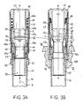
- Figure 3A is a central axial sectional view of a closing mechanism in accordance with the invention in the open position.
- Figure 3B shows the same as Fig. 3A while the closing mechanism is in its holder with the suction in the closed position.
- Fig. 1 The dentist's treatment machine shown in Fig. 1 is mainly known in prior art, and only its principal features will be described to permit an understanding of its background and to give an overall idea.
- the treatment machine shown in Fig. 1 comprises a central unit 24, which includes a control panel 23 for the operator and a basin part 22 above the control panel.
- a support arm 21 is attached to the top of the unit 24, said arm 21 being provided with an articulated arm 20.
- the articulated arm 20 is provided with a mobile arm 19, at whose end there is a console support 18.
- the dentist's control panel 15 is fixed, which is provided with the instrument modules 16.
- the unit 24 is connected to the patient's chair 11 by the intermediate of a support frame 13.
- the holder 10 for the suction tubes 14 is connected to the unit 24 by means of an arm 12 with several elbows.
- the outer end of one of the suction tubes 14 is provided with a closing mechanism 40 in accordance with the invention, which is connected with a suction-nozzle pipe 30.
- the treatment machine is provided with a connection unit 26, which is connected to the unit 24 by the intermediate of a cable 25.
- the connection unit 26 is provided with a foot control box 27, which is provided with a foot control 28.
- the central unit 24 of the treatment machine includes a filter system 32, on whose filter 32a the solid particles SP are collected.
- the filter system 32 communicates with a separation tank 34 through a pipe 33, the bottom part of said tank being provided with an exhaust pipe 36 for the removal of liquids, which is illustrated by the arrow W out .
- a pipe 35 Above the separation tank 34, there is a pipe 35, which communicates with a suction pump (not shown) in the direction of the arrow A out . It is also possible to use such prior-art systems in which the separation tank is not installed in the central unit, but elsewhere in the building in which the treatment machine is placed, and in such a case the separation tank usually semes for several treatment machines at the same time.
- a suction pipe 14 is connected, at whose end there is a closing mechanism 40 in accordance with the invention.
- a closing mechanism 40 By means of the nozzle pipe 30 connected to the suction duct of the closing mechanism 40, air, saliva, water, and solid particles are sucked out of the patient's mouth.
- the solid particles are, for example, pieces of tooth and amalgam, which had, in prior art, caused breakdowns of the diaphragm in diaphragm valves.
- the closing mechanism 40 is a substantially cylindrical piece, which fits in the operator's hand, and the main features of its operation are as follows.
- the closing mechanism 40 is opened, so that the negative pressure in the suction pump produces an air flow, which starts flowing in the direction of the arrows S shown in Fig. 3A through the suction nozzle 30, whereby the device can be used.
- the operator of the mechanism 40 may release his hold of the mechanism free of care, whereby the mechanism is returned automatically to its place by the effect of the weight of the suction hose 14, and at the same time the closing mechanism 40 is closed automatically because of its construction in accordance with the invention, which will be described below.
- FIG. 3A illustrates the closing mechanism in the open position, in which it is out of contact with its holder 10, i.e. normally in the operator's hand.
- Fig. 3B the closing mechanism is in the closed position, in which case it is in the wide opening 10b in the holder stably, by the effect of the weights of the hose 14 and of the fixed parts in the mechanism 40, resting on the shoulder 10b.
- the closing mechanism 40 comprises substantially cylindrical parts, which are circularly symmetric in relation to the central axis K-K.
- the closing mechanism is provided with a connector piece 41, by whose means the mechanism is connected to the outer end of the suction hose 14.
- a frame piece 43 is fixed to the inside of the connector piece 41, and an inner frame piece 46 is fixed to the outer end of said frame piece 43.
- the parts 41,43,46,50 and 51 of the mechanism form an integral unit permanently attached to the suction hose 14.
- a mobile annular part 42 On the connector piece 41 there is a mobile annular part 42, whose upper end can move in the groove 43a in the part 43.
- the top side of the annular part 42 i connected with a series of pins 44 (e.g. 2 pcs.), which are passed displaceably through openings in the part 43.
- a spiral spring 48 is placed against the upper shoulder 45b of a mobile inner ring 45, the opposite end of said spring 48 being placed against the lower shoulder 46a of the piece 46.
- the operator releases his grasp of it, whereby the weight of the suction hose 14 pulls the hose 14 through the wide opening 10a in the holder, whereby, at the final stage of the return movement of the hose 14, the shoulder 10b of the opening 10a meets the edge of the outer ring 42. Thereby the ring 42 presses the inner part 45 upwards by the intermediate of the pins 44.
- the spring 48 force is dimensioned so that the weight of the hose 14 and of the fixed parts is enough to overcome its spring force, whereby the valve disk 50 is pressed against the conical part 45k in the part 45.
- valve disk 50 may be provided with an elastic seal ring.
- the closing mechanism 40 in accordance with the invention is characterized by simple construction, easy operation, and reliability in operation, the latter feature being contributed to by the stable two positions of the valve mechanism 40, i.e. the stable open position provided by means of the spring 48, and the closed position provided by the force of gravity and secured by the suction.
- the mechanism 40 can be considered as a sort of a bi-stable (flip-flop) device.
- the fixed parts are expressly understood as parts permanently attached to the suction hose 14, and the mobile parts are understood as parts that can move in relation to said fixed parts.
- the closing mechanism 40 is placed in support of its holder 10, said mobile parts are supported on the holder 10 as immobile, whereas the fixed parts, together with the suction hose 14, are shifted axially downwards by the effect of the force of gravity and finally as aided by the outside atmospheric pressure, whereby the mechanism 40 is closed reliably.
- the closing mechanism in accordance with the invention is opened and closed by means of a linear movement in the direction of the longitudinal axis of the suction hose without any movement of rotation. It is partly owing to this that the construction can be made simple and reliable.
Landscapes
- Health & Medical Sciences (AREA)
- Dentistry (AREA)
- Epidemiology (AREA)
- Life Sciences & Earth Sciences (AREA)
- Animal Behavior & Ethology (AREA)
- General Health & Medical Sciences (AREA)
- Public Health (AREA)
- Veterinary Medicine (AREA)
- Dental Tools And Instruments Or Auxiliary Dental Instruments (AREA)
Applications Claiming Priority (2)
| Application Number | Priority Date | Filing Date | Title |
|---|---|---|---|
| FI900995 | 1990-02-27 | ||
| FI900995A FI85102C (fi) | 1990-02-27 | 1990-02-27 | Tillslutningsmekanism foer suganordningen av en tandvaordsmaskin. |
Publications (1)
| Publication Number | Publication Date |
|---|---|
| EP0445091A1 true EP0445091A1 (de) | 1991-09-04 |
Family
ID=8529960
Family Applications (1)
| Application Number | Title | Priority Date | Filing Date |
|---|---|---|---|
| EP91850013A Withdrawn EP0445091A1 (de) | 1990-02-27 | 1991-01-23 | Schlussmechanismus eines zahnärztlichen Absauggerätes |
Country Status (3)
| Country | Link |
|---|---|
| EP (1) | EP0445091A1 (de) |
| JP (1) | JPH0732790B2 (de) |
| FI (1) | FI85102C (de) |
Cited By (5)
| Publication number | Priority date | Publication date | Assignee | Title |
|---|---|---|---|---|
| WO1992006650A1 (en) * | 1990-10-23 | 1992-04-30 | Markku Hirvikangas | A suction device to be used in dental care |
| EP0547014A1 (de) * | 1991-11-08 | 1993-06-16 | Planmeca Oy | Absaugventil für eine Absaugvorrichtung einer zahnärztlichen Einheit |
| WO1993019697A1 (de) * | 1992-04-02 | 1993-10-14 | Trawoeger Werner | Einrichtung an einer zahnärztlichen absauganlage |
| US5868701A (en) * | 1996-03-19 | 1999-02-09 | Powers, Jr.; Carleton A. | Medical suctioning bacteria valve and related method |
| DE10038422B4 (de) * | 2000-08-07 | 2009-09-10 | Kaltenbach & Voigt Gmbh & Co. Kg | Vorrichtung zum Abscheiden von Luft aus einem Abwassergemisch, insbesondere für einen medizinischen oder dentalmedizinischen Behandlungsplatz |
Families Citing this family (1)
| Publication number | Priority date | Publication date | Assignee | Title |
|---|---|---|---|---|
| JP6139933B2 (ja) * | 2013-03-25 | 2017-05-31 | 株式会社モリタ東京製作所 | 取り付け部材、吸引用器具、管状部材、および、診療用装置 |
Citations (2)
| Publication number | Priority date | Publication date | Assignee | Title |
|---|---|---|---|---|
| EP0152390A2 (de) * | 1984-02-13 | 1985-08-21 | Mediplast AB | Saugvorrichtung |
| EP0254687A1 (de) * | 1986-07-24 | 1988-01-27 | Cattani S.P.A. | Vorrichtung zum Absperren der Absaugung durch die einzelnen Rohrleitungen einer Zahnbehandlungseinrichtung |
-
1990
- 1990-02-27 FI FI900995A patent/FI85102C/fi not_active IP Right Cessation
-
1991
- 1991-01-23 EP EP91850013A patent/EP0445091A1/de not_active Withdrawn
- 1991-02-26 JP JP3069291A patent/JPH0732790B2/ja not_active Expired - Lifetime
Patent Citations (2)
| Publication number | Priority date | Publication date | Assignee | Title |
|---|---|---|---|---|
| EP0152390A2 (de) * | 1984-02-13 | 1985-08-21 | Mediplast AB | Saugvorrichtung |
| EP0254687A1 (de) * | 1986-07-24 | 1988-01-27 | Cattani S.P.A. | Vorrichtung zum Absperren der Absaugung durch die einzelnen Rohrleitungen einer Zahnbehandlungseinrichtung |
Cited By (6)
| Publication number | Priority date | Publication date | Assignee | Title |
|---|---|---|---|---|
| WO1992006650A1 (en) * | 1990-10-23 | 1992-04-30 | Markku Hirvikangas | A suction device to be used in dental care |
| EP0547014A1 (de) * | 1991-11-08 | 1993-06-16 | Planmeca Oy | Absaugventil für eine Absaugvorrichtung einer zahnärztlichen Einheit |
| US5267586A (en) * | 1991-11-08 | 1993-12-07 | Planmeca Oy | Shutoff valve mechanism for the oral evacuator of a dental unit |
| WO1993019697A1 (de) * | 1992-04-02 | 1993-10-14 | Trawoeger Werner | Einrichtung an einer zahnärztlichen absauganlage |
| US5868701A (en) * | 1996-03-19 | 1999-02-09 | Powers, Jr.; Carleton A. | Medical suctioning bacteria valve and related method |
| DE10038422B4 (de) * | 2000-08-07 | 2009-09-10 | Kaltenbach & Voigt Gmbh & Co. Kg | Vorrichtung zum Abscheiden von Luft aus einem Abwassergemisch, insbesondere für einen medizinischen oder dentalmedizinischen Behandlungsplatz |
Also Published As
| Publication number | Publication date |
|---|---|
| JPH0732790B2 (ja) | 1995-04-12 |
| FI900995A7 (fi) | 1991-08-28 |
| FI85102C (fi) | 1992-03-10 |
| FI85102B (fi) | 1991-11-29 |
| FI900995A0 (fi) | 1990-02-27 |
| JPH04220250A (ja) | 1992-08-11 |
Similar Documents
| Publication | Publication Date | Title |
|---|---|---|
| US5267586A (en) | Shutoff valve mechanism for the oral evacuator of a dental unit | |
| US5546982A (en) | Automatic swimming pool cleaners and associated components | |
| US3570525A (en) | Stem-actuated tiltable valve | |
| US6261254B1 (en) | Lever-style drain assembly for urine collection container | |
| EP0757543B1 (de) | Vorrichtung zur abnahme und zur messung von körperflüssigkeiten | |
| US3078579A (en) | Dental aspirator with splash baffle | |
| US4957491A (en) | Combination fluid collection and disposal apparatus | |
| US4522592A (en) | Valve structure for an oral evacuator system | |
| US3847573A (en) | Dental office system | |
| US3988134A (en) | Dental office system | |
| FI85102B (fi) | Tillslutningsmekanism foer suganordningen av en tandvaordsmaskin. | |
| US4558696A (en) | Water trap | |
| US3938539A (en) | Apparatus for leading off air in connection with the measuring of the flow of a liquid | |
| JPS6323643A (ja) | 患者から試料採取した気流中のガスから液体を分離するための装置 | |
| US4589442A (en) | Valve for suction installation | |
| ES2068945T3 (es) | Adaptador de filtro con lavado a contra-corriente. | |
| US3982322A (en) | Arrangement for the switching on-and-off of a pressurized medium flow | |
| RU2140294C1 (ru) | Отсасыватель | |
| KR910011623A (ko) | 용기로의 유체 유입 제어장치 | |
| EP0749728A1 (de) | Steuerungseinrichtung für eine Filterkonsole in zahnärztlichen Absauganlagen | |
| SE467906B (sv) | Tandlaekaranordning foer inmatande av desinfektionsmedel i ett vattenledningsnaet | |
| JPH0587532U (ja) | 流量校正用サンプリング装置 | |
| Moyes, DG,* Cleaton-Jones, P.** & Foster | The design of four anaesthetic scavenging devices | |
| EP0635669A1 (de) | Verbindungsvorrichtung | |
| JPH06346499A (ja) | 真空弁制御装置 |
Legal Events
| Date | Code | Title | Description |
|---|---|---|---|
| PUAI | Public reference made under article 153(3) epc to a published international application that has entered the european phase |
Free format text: ORIGINAL CODE: 0009012 |
|
| AK | Designated contracting states |
Kind code of ref document: A1 Designated state(s): AT BE CH DE DK ES FR GB GR IT LI LU NL SE |
|
| STAA | Information on the status of an ep patent application or granted ep patent |
Free format text: STATUS: THE APPLICATION IS DEEMED TO BE WITHDRAWN |
|
| 18D | Application deemed to be withdrawn |
Effective date: 19920305 |