EP0445271B1 - Structure a levitation et de deplacement dotee d'un systeme de reglage d'ecartement - Google Patents
Structure a levitation et de deplacement dotee d'un systeme de reglage d'ecartement Download PDFInfo
- Publication number
- EP0445271B1 EP0445271B1 EP90914524A EP90914524A EP0445271B1 EP 0445271 B1 EP0445271 B1 EP 0445271B1 EP 90914524 A EP90914524 A EP 90914524A EP 90914524 A EP90914524 A EP 90914524A EP 0445271 B1 EP0445271 B1 EP 0445271B1
- Authority
- EP
- European Patent Office
- Prior art keywords
- transport system
- air gap
- magnetic track
- magnetic
- track transport
- Prior art date
- Legal status (The legal status is an assumption and is not a legal conclusion. Google has not performed a legal analysis and makes no representation as to the accuracy of the status listed.)
- Expired - Lifetime
Links
- 230000001419 dependent effect Effects 0.000 claims description 3
- 230000005684 electric field Effects 0.000 claims description 2
- 238000010276 construction Methods 0.000 claims 1
- 230000004907 flux Effects 0.000 claims 1
- 238000005259 measurement Methods 0.000 claims 1
- 230000001105 regulatory effect Effects 0.000 claims 1
- 238000000926 separation method Methods 0.000 claims 1
- 125000006850 spacer group Chemical group 0.000 claims 1
- 238000005339 levitation Methods 0.000 abstract description 2
- 239000000725 suspension Substances 0.000 description 7
- 229910000831 Steel Inorganic materials 0.000 description 1
- 238000011161 development Methods 0.000 description 1
- 230000018109 developmental process Effects 0.000 description 1
- 238000006073 displacement reaction Methods 0.000 description 1
- 230000003993 interaction Effects 0.000 description 1
- 239000002184 metal Substances 0.000 description 1
- 239000010959 steel Substances 0.000 description 1
- 238000004804 winding Methods 0.000 description 1
Images

Classifications
-
- B—PERFORMING OPERATIONS; TRANSPORTING
- B61—RAILWAYS
- B61B—RAILWAY SYSTEMS; EQUIPMENT THEREFOR NOT OTHERWISE PROVIDED FOR
- B61B13/00—Other railway systems
- B61B13/08—Sliding or levitation systems
Definitions
- the present invention relates to an air gap control for a suspension / chassis of a track-bound magnetic railway transport system.
- the vehicles are driven by a long stator motor installed in the track.
- the electric traveling field in the windings of the long stator motor interacts with the magnetic forces of the permanent magnets of the suspension / chassis. This interaction takes place without contact. It must be ensured that this freedom of contact (air gap) is guaranteed.
- the magnetic forces that act via the steel track here the sheet metal packs of the long stator
- This air gap is to be set depending on the load by the air gap control, i.e.
- the air gap is to be reduced by the servomotors, which has the consequence that the magnetic attraction forces between the permanent magnets of the suspension / chassis and of the guideway with an integrated long stator.
- Load-dependent mechanical and hydraulic air gap controls and electronically controlled carrying and guiding systems are known.
- the mechanical air gap control is complex, expensive and has limited functionality, poor adjustability and wide adjustment ranges.
- a hydraulic air gap control of a track-bound magnetic rail transport system with a linear motor integrated in the guideway and permanent magnets in the suspension / chassis of the vehicle is known, in which a star frame serves as a carrier for all necessary components, with each on the side members of the star frame Hydraulically driven pistons for adjusting the height of the vertical rollers running below the carriageway are arranged at both ends in cylinders, and the height is adjusted using a complex hydraulic and pneumatic system in accordance with the relative displacement between the magnetic railway cabin and the star frame when the external forces change as a result of the interposition Spring device occurs.
- An electronically controlled carrying and guiding system is complex and only economical for high-speed applications.
- the object of the present invention is to provide a simple, inexpensive, easily adjustable air gap control system with a small adjustment range. This object is achieved by the characterizing features of claim 1. Advantageous refinements and / or further developments can be found in the subclaims.
- Figure 1 shows a section through a levitation / chassis of a magnetic railway vehicle with the air gap control according to the invention in cooperation with the magnetic railway track.
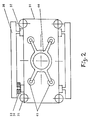
- FIG. 2 shows the top view of the suspension / chassis from FIG. 1.
- the magnetic track route consists of the route carrier and the route profile.
- the guideway beam is constructed from the support profile 11 and the cross connector 12.
- the guideway profile has the support rail 21, the side guide profile 22 and the long stator 23.
- the suspension / chassis contains the star frame 31, the spindle drive 32, the servomotor 321, the upper vertical rollers 33, the lower vertical rollers 34, the side guide roller 35 and the magnetic strip 36.
- the magnetic track cabin (not shown) can be connected to the star frame 31, for example via the air bellows 45 and the turntable 44 connected.
- the air gap control is carried out according to the invention by load-dependent target specifications by means of the actuators 321.
- the actuators 321 are attached on both sides to the end of the longitudinal members of a rectangular chassis frame 31.
- the air gap control also makes it possible to design the star frame 31 in such a way that a free space is created in the central region thereof, as shown in FIG. 1. This means that points and crossings in the middle of the magnetic track can be used be carried out in such a way that they protrude above the upper edge of the track profile and can still be driven on by the magnetic railway vehicles.
- the spindle drive 32 so that the distance between the long stator 23 and the magnetic strip 36 can be increased such that the flow of force is interrupted by separating the electrical field of the long stator 23 and the magnetic field of the permanent magnets of the magnetic strip 36 and so that a safe drive shutdown can be carried out, for example, in the parking area of the transport system or for other requirements.
- This is of great importance for the safety of driving and shunting operations. This makes it possible to drive different vehicles in the same converter area of the drive system, with the result that this possibility of switching off the drive of individual vehicles means that they can be parked at a short distance from one another and thus a considerable reduction in the length of the parking track is possible.
- the support arms of the magnetic strips 36 are equipped with support points, not shown, which are positioned above the upper running surface of the support rail 21 in such a way that they support the vehicle weight at the maximum distance required for safe drive shutdown supported on the upper support rail 21 and so a complete relief of the upper vertical rollers 33 is achieved.
- This avoids deformation of the elastic tread of these vertical rollers during longer service lives.
- This support of the vehicle weight also acts as a holding brake to safely park a vehicle.
- the magnetic strip 36 can also be connected to the star frame 31 and the air gap control can be carried out by adjusting the height of the upper vertical rollers 33.
Landscapes
- Engineering & Computer Science (AREA)
- Transportation (AREA)
- Mechanical Engineering (AREA)
- Control Of Vehicles With Linear Motors And Vehicles That Are Magnetically Levitated (AREA)
- Linear Motors (AREA)
Abstract
Claims (7)
- Système de transport à voie magnétique constitué de voies avec stator linéaire intégré (23) et châssis à sustentation avec des aimants permanents fixés sur des glissières magnétiques (36) pour porter et entraîner les véhicules, dans le cas de chacun desquels un cadre rigide (31) sert de support pour tous les composants nécessaires et dans le cas desquels, sur chacun des longerons du cadre rigide (31), des deux côtés, aux extrémités, les mécanismes d'entrainement pour le réglage en hauteur, soit des glissières magnétiques (36) soit des galets de guidage et d'écartement (33, 34), sont disposés pour la régulation de l'entrefer entre les aimants permanents, fixés sur les glissières magnétiques (36), et les stators linéaires (23) et dans le cas desquels on procède au réglage en hauteur en fonction de la charge, système caractérisé- par le fait qu'en ce qui concerne le mécanisme d'entrainement, il s'agit d'un moteur de positionnement (321) à entraînement électrique ou hydraulique- et par le fait qu'à l'aide d'un dispositif de mesure de la force on mesure la contrainte des galets de guidage supérieurs (33) pour obtenir une valeur de mesure pour la régulation de l'entrefer en cas de contrainte différente provoquée par le poids.
- Système de transport à voie magnétique selon la revendication 1, caractérisé par le fait que la régulation de l'entrefer est commandée électroniquement, en fonction d'une valeur prescrite de la contrainte.
- Système de transport à voie magnétique selon la revendication 1 ou 2, caractérisé par le fait que de brèves pointes de contrainte sont éliminées de la régulation au moyen d'une régulation à valeur de seuil fonction du poids et/ou du temps.
- Système de transport à voie magnétique selon l'une des revendications précédentes, caractérisé par le fait que le cadre rigide (31) est réalisé de façon qu'apparaisse, dans la zone médiane du châssis, dans l'axe longitudinal, un espace libre qui va jusqu'au-dessus du bord supérieur du profilé de voie, pour pouvoir franchir des tronçons médians d'aiguillage ou de croisement.
- Système de transport à voie magnétique selon l'une des revendications précédentes, caractérisé par le fait que grâce aux moteurs de positionnement (321), on peut augmenter la distance entre le stator linéaire (23) et la glissière magnétique (36) de façon à interrompre le flux de force par séparation du champ électrique du stator linéaire (23) d'avec le champ magnétique des aimants permanents de la glissière magnétique (36) et à obtenir ainsi un arrêt sûr du mécanisme d'entrainement.
- Système de transport à voie magnétique selon la revendication 5, caractérisé par le fait que grâce à une conception appropriée des bras supports des glissières magnétiques (36) avec des points d'appui qui sont placés au-dessus de la surface de roulement supérieure du rail porteur (21), à la distance maximale nécessaire pour l'arrêt sûr du mécanisme d'entrainement, il se produit en même temps un appui du poids du véhicule sur la surface de roulement supérieure des rails de la voie, et il se fait donc une décharge complète des galets verticaux supérieurs (33) du châssis à sustentation.
- Système de transport à voie magnétique selon la revendication 6, caractérisé par le fait qu'en cas de décharge complète des galets verticaux supérieurs (33), les points d'appui des bras supports des glissières magnétiques agissent comme freins de maintien.
Applications Claiming Priority (3)
| Application Number | Priority Date | Filing Date | Title |
|---|---|---|---|
| DE3931797 | 1989-09-23 | ||
| DE19893931797 DE3931797A1 (de) | 1989-09-23 | 1989-09-23 | Schwebe-/fahrgestell mit stellmotorenbetriebener luftspaltregelung fuer das m-bahn system |
| PCT/EP1990/001604 WO1991004182A1 (fr) | 1989-09-23 | 1990-09-21 | Structure a levitation et de deplacement dotee d'un systeme de reglage d'ecartement |
Publications (2)
| Publication Number | Publication Date |
|---|---|
| EP0445271A1 EP0445271A1 (fr) | 1991-09-11 |
| EP0445271B1 true EP0445271B1 (fr) | 1994-12-28 |
Family
ID=6390043
Family Applications (1)
| Application Number | Title | Priority Date | Filing Date |
|---|---|---|---|
| EP90914524A Expired - Lifetime EP0445271B1 (fr) | 1989-09-23 | 1990-09-21 | Structure a levitation et de deplacement dotee d'un systeme de reglage d'ecartement |
Country Status (7)
| Country | Link |
|---|---|
| EP (1) | EP0445271B1 (fr) |
| JP (1) | JPH04501950A (fr) |
| CA (1) | CA2042387A1 (fr) |
| DE (2) | DE3931797A1 (fr) |
| DK (1) | DK0445271T3 (fr) |
| ES (1) | ES2066227T3 (fr) |
| WO (1) | WO1991004182A1 (fr) |
Families Citing this family (6)
| Publication number | Priority date | Publication date | Assignee | Title |
|---|---|---|---|---|
| US5688778A (en) * | 1989-05-15 | 1997-11-18 | Institute Of Organic Chemistry And Biochemistry Of The Academy Of Sciences Of The Czech Republic | Nucleoside analogs |
| DE4206491C2 (de) * | 1992-03-02 | 1996-04-11 | Magnetbahn Gmbh | Meßvorrichtung und Verfahren zur Bestimmung der Radkräfte von Magnetbahnfahrzeugen |
| DE102008060569A1 (de) | 2008-12-04 | 2010-06-10 | Schaeffler Kg | Lageranordnung mit Magnetlagerabschnitt sowie Verfahren zur Regelung einer oder der Lageranordnung |
| CN107160168B (zh) * | 2017-06-28 | 2023-11-28 | 翟泉来 | 小型可拆装移动式数控钻铣孔机床 |
| CN109228884B (zh) * | 2018-10-11 | 2020-05-05 | 湖南磁浮技术研究中心有限公司 | 一种磁悬浮列车及其悬浮架 |
| CN111762206A (zh) * | 2020-07-14 | 2020-10-13 | 九洲运通(北京)超导新技术产业发展有限公司 | 超导磁浮内置悬挂式空轨交通系统 |
Family Cites Families (11)
| Publication number | Priority date | Publication date | Assignee | Title |
|---|---|---|---|---|
| FR2279597A1 (fr) * | 1974-07-26 | 1976-02-20 | Heidelberg Goetz | Procede et dispositif de support magnetique de vehicules |
| DE2436106C2 (de) * | 1974-07-26 | 1986-10-23 | Heidelberg, Götz, Dipl.-Phys., 8130 Starnberg | Magnetschwebefahrzeug mit anziehenden Dauermagneten und geregelten Elektromagneten |
| JPS51100515A (ja) * | 1975-02-28 | 1976-09-04 | Tokyo Shibaura Electric Co | Jodendojikifujosha |
| DE2545336A1 (de) * | 1975-10-09 | 1977-04-21 | Siemens Ag | Seitenfuehrungseinrichtung fuer eine magnetische schwebebahn |
| DE2711994C3 (de) * | 1977-03-18 | 1980-05-14 | Goetz Dipl.-Phys. 8136 Percha Heidelberg | Fahrzeug, das gegenüber einem Fahrweg mit Hilfe einer anziehenden magnetischen Einrichtung und einer Zusatzkrafteinrichtung gehalten wird |
| DE2813023A1 (de) * | 1977-03-18 | 1979-09-27 | Heidelberg Goetz | Mindestens teilweise magnetisch arbeitendes system zum halten eines fahrzeugs gegenueber einem fahrweg |
| DE3107341C2 (de) * | 1981-02-26 | 1985-08-01 | Magnet-Bahn Gmbh, 8130 Starnberg | Magnetschwebe-Fahrzeug mit gegenüber dem Tragteil abgefedertem Nutzlastträger |
| DE3134049A1 (de) * | 1981-08-28 | 1983-03-10 | Herbert Prof. Dr.-Ing. 3300 Braunschweig Weh | Magnetregelung mit externen stellgliedern |
| JP2572016B2 (ja) * | 1986-01-08 | 1997-01-16 | 東洋電機製造株式会社 | 鋼板懸垂搬送の速度,吸引力制御装置 |
| DE3637844A1 (de) * | 1986-11-06 | 1988-05-19 | Messerschmitt Boelkow Blohm | Schienenfahrzeug mit spurkranzraedern |
| JPH01152905A (ja) * | 1987-12-08 | 1989-06-15 | Mitsubishi Electric Corp | 磁気浮上搬送装置 |
-
1989
- 1989-09-23 DE DE19893931797 patent/DE3931797A1/de not_active Ceased
-
1990
- 1990-09-21 WO PCT/EP1990/001604 patent/WO1991004182A1/fr not_active Ceased
- 1990-09-21 DE DE59008141T patent/DE59008141D1/de not_active Expired - Fee Related
- 1990-09-21 DK DK90914524T patent/DK0445271T3/da active
- 1990-09-21 ES ES90914524T patent/ES2066227T3/es not_active Expired - Lifetime
- 1990-09-21 EP EP90914524A patent/EP0445271B1/fr not_active Expired - Lifetime
- 1990-09-21 CA CA 2042387 patent/CA2042387A1/fr not_active Abandoned
- 1990-09-21 JP JP2513595A patent/JPH04501950A/ja active Pending
Also Published As
| Publication number | Publication date |
|---|---|
| JPH04501950A (ja) | 1992-04-02 |
| CA2042387A1 (fr) | 1991-03-24 |
| DK0445271T3 (da) | 1995-02-27 |
| WO1991004182A1 (fr) | 1991-04-04 |
| ES2066227T3 (es) | 1995-03-01 |
| DE3931797A1 (de) | 1991-04-11 |
| EP0445271A1 (fr) | 1991-09-11 |
| DE59008141D1 (de) | 1995-02-09 |
Similar Documents
| Publication | Publication Date | Title |
|---|---|---|
| EP1725418B1 (fr) | Voie pour train a sustentation magnetique a frein a courants de foucault | |
| EP2195186A2 (fr) | Véhicule à sustentation magnétique, et procédé de soulèvement et/ou de descente de ce véhicule | |
| DE68918811T2 (de) | Stützapparat für Fahrzeuglinearmotor. | |
| EP0445271B1 (fr) | Structure a levitation et de deplacement dotee d'un systeme de reglage d'ecartement | |
| DE2140103B1 (de) | Magnetische fuehrung einer schienengebundenen magnetschwebebahn | |
| DE2556076B2 (de) | Magnetschwebefahrzeug | |
| DE4025313C2 (de) | Schienengeführte Transporteinrichtung sowie hierfür bestimmte Führungsschienen und aus Transporteinrichtung und Führungsschienen bestehendes Transportsystem | |
| DE3914093C2 (fr) | ||
| DE102017210428A1 (de) | Linearmotoranordnung mit zwei Antriebssträngen | |
| EP1145929B1 (fr) | Appareil de mise en action des freins de véhicules ferroviaires | |
| WO1996003289A1 (fr) | Chassis flottant a suspension electromagnetique | |
| DE1755174C3 (de) | Laufwerk für elektrische Einschienenbahn-Fahrzeuge | |
| DE4309722C1 (de) | Fahrgestell mit konstantem Luftspalt für Fahrzeuge mit Linearmotorantrieb | |
| AT328501B (de) | Zweiachsiges drehgestell fur schienenfahrzeuge | |
| DE3236498A1 (de) | Rad-schiene-fahrzeug | |
| DE102006028689B4 (de) | Vorrichtung zur Spurführung eines Straßenfahrzeuges | |
| EP0678415A1 (fr) | Véhicule à moteur linéaire avec commande magnétique permanente et électromagnétique | |
| DE2322150C3 (de) | Weiche mit einer Fahrbahnverzweigung in einer vertikalen Ebene für eine Magnetschwebebahn | |
| DE2407522A1 (de) | Linearmotorantrieb insbesondere fuer ein spurgebundenes schwebefahrzeug | |
| DE2953778C1 (de) | Bremseinrichtung fuer Magnetschwebefahrzeug | |
| DE2933446A1 (de) | Bremseinrichtung fuer magnetschwebefahrzeug | |
| DE2417239A1 (de) | Korrekturspindel fuer universalfahrzeuge und einschienenbahn | |
| DE29705511U1 (de) | Elektromagnetisch getragenes Schwebegestell | |
| DE2545336A1 (de) | Seitenfuehrungseinrichtung fuer eine magnetische schwebebahn | |
| DE2612559A1 (de) | Anordnung fuer ein magnetschwebefahrzeug |
Legal Events
| Date | Code | Title | Description |
|---|---|---|---|
| PUAI | Public reference made under article 153(3) epc to a published international application that has entered the european phase |
Free format text: ORIGINAL CODE: 0009012 |
|
| 17P | Request for examination filed |
Effective date: 19910614 |
|
| AK | Designated contracting states |
Kind code of ref document: A1 Designated state(s): DE DK ES FR GB IT NL |
|
| 17Q | First examination report despatched |
Effective date: 19930621 |
|
| GRAA | (expected) grant |
Free format text: ORIGINAL CODE: 0009210 |
|
| REF | Corresponds to: |
Ref document number: 59008141 Country of ref document: DE Date of ref document: 19950209 |
|
| REG | Reference to a national code |
Ref country code: DK Ref legal event code: T3 |
|
| REG | Reference to a national code |
Ref country code: ES Ref legal event code: FG2A Ref document number: 2066227 Country of ref document: ES Kind code of ref document: T3 |
|
| GBT | Gb: translation of ep patent filed (gb section 77(6)(a)/1977) |
Effective date: 19950220 |
|
| ET | Fr: translation filed | ||
| ITF | It: translation for a ep patent filed | ||
| PLBE | No opposition filed within time limit |
Free format text: ORIGINAL CODE: 0009261 |
|
| STAA | Information on the status of an ep patent application or granted ep patent |
Free format text: STATUS: NO OPPOSITION FILED WITHIN TIME LIMIT |
|
| 26N | No opposition filed | ||
| PGFP | Annual fee paid to national office [announced via postgrant information from national office to epo] |
Ref country code: GB Payment date: 19980911 Year of fee payment: 9 |
|
| PGFP | Annual fee paid to national office [announced via postgrant information from national office to epo] |
Ref country code: NL Payment date: 19980923 Year of fee payment: 9 Ref country code: DK Payment date: 19980923 Year of fee payment: 9 |
|
| PGFP | Annual fee paid to national office [announced via postgrant information from national office to epo] |
Ref country code: FR Payment date: 19980925 Year of fee payment: 9 Ref country code: ES Payment date: 19980925 Year of fee payment: 9 |
|
| PGFP | Annual fee paid to national office [announced via postgrant information from national office to epo] |
Ref country code: DE Payment date: 19981123 Year of fee payment: 9 |
|
| PG25 | Lapsed in a contracting state [announced via postgrant information from national office to epo] |
Ref country code: GB Free format text: LAPSE BECAUSE OF NON-PAYMENT OF DUE FEES Effective date: 19990921 Ref country code: DK Free format text: LAPSE BECAUSE OF NON-PAYMENT OF DUE FEES Effective date: 19990921 |
|
| PG25 | Lapsed in a contracting state [announced via postgrant information from national office to epo] |
Ref country code: ES Free format text: LAPSE BECAUSE OF NON-PAYMENT OF DUE FEES Effective date: 19990922 |
|
| PG25 | Lapsed in a contracting state [announced via postgrant information from national office to epo] |
Ref country code: NL Free format text: LAPSE BECAUSE OF NON-PAYMENT OF DUE FEES Effective date: 20000401 |
|
| GBPC | Gb: european patent ceased through non-payment of renewal fee |
Effective date: 19990921 |
|
| PG25 | Lapsed in a contracting state [announced via postgrant information from national office to epo] |
Ref country code: FR Free format text: LAPSE BECAUSE OF NON-PAYMENT OF DUE FEES Effective date: 20000531 |
|
| NLV4 | Nl: lapsed or anulled due to non-payment of the annual fee |
Effective date: 20000401 |
|
| REG | Reference to a national code |
Ref country code: DK Ref legal event code: EBP |
|
| PG25 | Lapsed in a contracting state [announced via postgrant information from national office to epo] |
Ref country code: DE Free format text: LAPSE BECAUSE OF NON-PAYMENT OF DUE FEES Effective date: 20000701 |
|
| REG | Reference to a national code |
Ref country code: FR Ref legal event code: ST |
|
| REG | Reference to a national code |
Ref country code: ES Ref legal event code: FD2A Effective date: 20001013 |
|
| PG25 | Lapsed in a contracting state [announced via postgrant information from national office to epo] |
Ref country code: IT Free format text: LAPSE BECAUSE OF NON-PAYMENT OF DUE FEES;WARNING: LAPSES OF ITALIAN PATENTS WITH EFFECTIVE DATE BEFORE 2007 MAY HAVE OCCURRED AT ANY TIME BEFORE 2007. THE CORRECT EFFECTIVE DATE MAY BE DIFFERENT FROM THE ONE RECORDED. Effective date: 20050921 |