EP0445529A1 - Dispositif hydraulique - Google Patents
Dispositif hydraulique Download PDFInfo
- Publication number
- EP0445529A1 EP0445529A1 EP19910101440 EP91101440A EP0445529A1 EP 0445529 A1 EP0445529 A1 EP 0445529A1 EP 19910101440 EP19910101440 EP 19910101440 EP 91101440 A EP91101440 A EP 91101440A EP 0445529 A1 EP0445529 A1 EP 0445529A1
- Authority
- EP
- European Patent Office
- Prior art keywords
- pressure
- line
- gear
- sealing plate
- control
- Prior art date
- Legal status (The legal status is an assumption and is not a legal conclusion. Google has not performed a legal analysis and makes no representation as to the accuracy of the status listed.)
- Granted
Links
- 238000007789 sealing Methods 0.000 claims abstract description 30
- 230000001105 regulatory effect Effects 0.000 claims description 4
- 238000011144 upstream manufacturing Methods 0.000 claims description 2
- 230000007935 neutral effect Effects 0.000 description 2
- 238000010276 construction Methods 0.000 description 1
- 230000004048 modification Effects 0.000 description 1
- 238000012986 modification Methods 0.000 description 1
- 230000035945 sensitivity Effects 0.000 description 1
Images


Classifications
-
- F—MECHANICAL ENGINEERING; LIGHTING; HEATING; WEAPONS; BLASTING
- F04—POSITIVE - DISPLACEMENT MACHINES FOR LIQUIDS; PUMPS FOR LIQUIDS OR ELASTIC FLUIDS
- F04C—ROTARY-PISTON, OR OSCILLATING-PISTON, POSITIVE-DISPLACEMENT MACHINES FOR LIQUIDS; ROTARY-PISTON, OR OSCILLATING-PISTON, POSITIVE-DISPLACEMENT PUMPS
- F04C14/00—Control of, monitoring of, or safety arrangements for, machines, pumps or pumping installations
- F04C14/24—Control of, monitoring of, or safety arrangements for, machines, pumps or pumping installations characterised by using valves controlling pressure or flow rate, e.g. discharge valves or unloading valves
- F04C14/26—Control of, monitoring of, or safety arrangements for, machines, pumps or pumping installations characterised by using valves controlling pressure or flow rate, e.g. discharge valves or unloading valves using bypass channels
- F04C14/265—Control of, monitoring of, or safety arrangements for, machines, pumps or pumping installations characterised by using valves controlling pressure or flow rate, e.g. discharge valves or unloading valves using bypass channels being obtained by displacing a lateral sealing face
Definitions
- the invention relates to a hydraulic system with a gear pump regulating its flow.
- the load pressure which prevails at a consumer directly acts on a pressure field which acts on the sealing plate.
- Such control of the sealing plate is not particularly precise.
- the hydraulic system with the characterizing feature of the main claim has the advantage that the delivery rate of the gear pump used in the hydraulic system can be controlled very precisely. Further advantages result from the subclaims.
- FIG. 1 a hydraulic system in a schematic representation
- Figure 2 a modification of the embodiment of Figure 1
- Figure 3 an application in a gear motor
- Figure 4 another variant
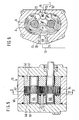
- Figure 5 a longitudinal section through a gear pump
- Figure 6 a section along II- II according to FIG. 5.
- 10 denotes a gear pump, which sucks pressure medium out of a container 12 via a suction line 11 and displaces it into a delivery line 13.
- Several directional control valves 14, 15 can be connected to the delivery line, of which consumer lines 16, 17 lead to consumers 18 and not shown.
- Each directional valve has a metering orifice 19 or 20 on the control slide, which are connected to chambers (not shown) to which a control line 21 is connected.
- a control line 23 is connected to the delivery line 13, which leads to the one end face 24 A of a pressure compensator 24.
- a branch line 25 branches off from the control line 21 and penetrates into a control line 26, which on the one hand opens at the end face 24 B of the pressure compensator 24 opposite the end face 24 A, and on the other hand at a pressure limiting valve 27.
- a control spring 28 also acts on the end face 24 B.
- a line 29 branches off from the control line 23, which opens into a line 30 which leads from the pressure compensator 24 to the gear pump and opens there at a sealing plate 31, which is discussed in more detail further on.
- a throttle 32 is arranged in line 29.
- a return line 34 leads from the interior of the gear pump 10 to the container.
- the outlet line 35 emanating from the pressure compensator 24 also opens into this return line, into which the outlet line 36 of the pressure limiting valve 27 in turn penetrates.
- a throttle 37 is arranged in the control line 21 before the line branch 25.
- the pressure compensator closes due to the signal pressure in line 21, which corresponds to that in line 13, so that no pressure medium can flow from the line 30 into the return line 35 via the pressure compensator 24.
- the pressure prevailing in the lines 13, 23, 29 and 30 presses the sealing plate 31 against the gear side surfaces, that is to say no pressure medium can flow out from the inside of the high pressure side to the low pressure side of the gear pump.
- the pressure in the delivery line 13 and the consumer line 16 now increases, and the load pressure at the consumer, that is to say that behind the throttle 19, is transmitted via the control line 21 to the end face 24 B of the pressure compensator.
- the pressure compensator opens, whereupon the pressure in the line 30 drops, that is to say a control pressure for the sealing plate 31 is formed in this line, but which is designed so that it is significantly lower than the pressure in line 23. If there is a pressure of 153 bar in the delivery line, for example, a pressure of 150 bar in control line 21 - the pressure difference arises at throttle 19 - so forms the pressure compensator in line 30, for example, a pressure of 120 bar. In this way, a pressure drop in line 30 is obtained, which contributes to improving the control sensitivity.
- the pressure relief valve 27 is a maximum pressure valve. If, for example, the maximum pressure in the hydraulic system is reached and the pressure relief valve 27 opens, the pressure compensator 24 immediately goes into the open position and thus relieves the pressure on the sealing plate 31 completely, so that all pressure medium conveyed by the gear pump 10 immediately flows from the high pressure to the low pressure side . So you get an internal pressure limitation.
- the throttle 37 is used to generate differential pressure for the pressure compensator control.
- Figure 2 differs from the above only in that it is a hydraulic system in which directional control valves are used in an open-center construction. In principle, however, this system works in the same way.
- the pressure compensator does not work to control the current for the consumer 18, but only as a maximum pressure limitation together with the pilot valve 27.
- the embodiment according to FIG. 3 is to a certain extent the reverse of the examples mentioned above, that is to say here a flow control of a gear motor with a sealing plate and pressure compensator takes place.
- the pressure difference required for the control is generated by an adjustable throttle 40, which is in the return line 41 is arranged from the gear motor 42 to the container.
- the pressure drop across the throttle 40 acts on the pressure compensator 24.
- the control pressure is generated in a line 45 which is connected to a line 29 which starts from the pressure line, specifically at a point upstream of the throttle 32
- the pressure compensator is controlled via the throttle 40 so that there is a low control pressure in the control line 45 when the pressure compensator is open, so that the sealing plate 31 has lifted off the gear side surfaces.
- the exemplary embodiment according to FIG. 4 differs from the previous one in that two gear pumps 10, 50 are provided which are driven by a common shaft.
- the sealing plate 31 is arranged on the gear pump 50, which is connected via its delivery line 51 to the delivery line 13 of the pump 10.
- the directional control valves 14, 15 are again designed as in the exemplary embodiment according to FIG. 1, where the load pressure-carrying control line 52 is brought to a pressure compensator 53, the other side of which is acted upon via a line 54 connected to the delivery line 13.
- a control line 55 leads from the pressure compensator 53 to the sealing plate 31.
- FIGS. 5 and 6 show the gear pump 10 used in the hydraulic system. However, this is not shown in all its constructive details. It has a housing 60 which is closed on both sides by covers 61, 62. In the interior of the housing, two gearwheels 63, 64 mesh with one another in external engagement, the shafts 65, 66 of which are arranged in bearing bodies 67, 68. Between the bearing body 68 and the gear wheels, the sealing plate 31 is arranged, which has the contour of the interior and covers the gear wheels. The bearing body 67, 68 and the sealing plate 31 and also the gears are mounted in the housing 60 with little axial play.
- two pressure fields A and B are formed, of which the pressure field A is continuously acted upon by high pressure, which prevails in a housing bore 70 which penetrates from the outside into a recess 71 at the level of the gearwheels, which extends along of the housing interior extends.
- the high-pressure side HD to which the delivery line 13 is connected is located at the bore 70.
- a bore 72 is formed in the housing, which opens into a recess 73, which likewise runs along the interior.
- the bore 72 is the low-pressure side ND, from which the line 11 leads to the container 12, from which the gear pump sucks in pressure medium.
- the pressure field B is the controlled pressure field to which the line 30 according to FIG. 1 is connected. It is identified in FIG. 6 as a short, dot-dash hole.
- the sealing plate can be pressed onto the gearwheels 63, or when the pressure field B is relieved, the sealing plate 31 is lifted off the gearwheels, since the high pressure of the machine prevails below it.
- the sealing plate is somewhat movable in the axial direction. When it has lifted off the gearwheel side surfaces, the pumped pressure medium flows directly from the high pressure side HD along the gearwheels and below the sealing plate to the tank side. The gear pump then delivers in neutral circulation.
Landscapes
- Engineering & Computer Science (AREA)
- Physics & Mathematics (AREA)
- Fluid Mechanics (AREA)
- Mechanical Engineering (AREA)
- General Engineering & Computer Science (AREA)
- Rotary Pumps (AREA)
- Details And Applications Of Rotary Liquid Pumps (AREA)
Applications Claiming Priority (2)
| Application Number | Priority Date | Filing Date | Title |
|---|---|---|---|
| DE4007073A DE4007073A1 (de) | 1990-03-07 | 1990-03-07 | Hydraulikanlage |
| DE4007073 | 1990-03-07 |
Publications (2)
| Publication Number | Publication Date |
|---|---|
| EP0445529A1 true EP0445529A1 (fr) | 1991-09-11 |
| EP0445529B1 EP0445529B1 (fr) | 1994-10-19 |
Family
ID=6401559
Family Applications (1)
| Application Number | Title | Priority Date | Filing Date |
|---|---|---|---|
| EP91101440A Expired - Lifetime EP0445529B1 (fr) | 1990-03-07 | 1991-02-04 | Dispositif hydraulique |
Country Status (2)
| Country | Link |
|---|---|
| EP (1) | EP0445529B1 (fr) |
| DE (2) | DE4007073A1 (fr) |
Cited By (3)
| Publication number | Priority date | Publication date | Assignee | Title |
|---|---|---|---|---|
| FR2706541A1 (fr) * | 1993-06-11 | 1994-12-23 | Renault Vehicules Ind | Procédé de régulation de la pression et du débit de refoulement d'une pompe volumétrique et pompe volumétrique pour la mise en Óoeuvre du procédé. |
| EP1048879A3 (fr) * | 1999-04-30 | 2001-01-17 | Hydraulik-Ring GmbH | Alimentation en fluide sous pression d' une transmission de type CVT |
| WO2007068233A1 (fr) * | 2005-12-17 | 2007-06-21 | Luk Lamellen Und Kupplungsbau Beteiligungs Kg | Passage rotatif et dispositif de transmission d'un couple de rotation dote d'un passage rotatif |
Families Citing this family (3)
| Publication number | Priority date | Publication date | Assignee | Title |
|---|---|---|---|---|
| DE19917593C2 (de) | 1999-04-19 | 2002-05-02 | Hydraulik Ring Gmbh | Hydraulische Verdrängermaschine |
| DE19924855A1 (de) * | 1999-04-30 | 2000-11-02 | Hydraulik Ring Gmbh | Druckmittelversorgung eines CVT-Getriebes |
| DE102014216038A1 (de) | 2014-08-13 | 2016-02-18 | Robert Bosch Gmbh | Zahnradmaschine mit schaltbarem internem Umlauf |
Citations (4)
| Publication number | Priority date | Publication date | Assignee | Title |
|---|---|---|---|---|
| FR1080123A (fr) * | 1952-05-24 | 1954-12-07 | Borg Warner | Perfectionnements relatifs aux systèmes de transmission hydraulique |
| DE1040904B (de) * | 1952-05-21 | 1958-10-09 | Borg Warner | Hydraulische Pumpenanlage |
| GB1031667A (en) * | 1962-04-05 | 1966-06-02 | Cessna Aircraft Co | Hydraulic motor system with delayed pressure loading |
| DE2335054A1 (de) * | 1972-07-10 | 1974-01-31 | Komatsu Mfg Co Ltd | Zahnradpumpe bzw. zahnradmotor |
-
1990
- 1990-03-07 DE DE4007073A patent/DE4007073A1/de not_active Withdrawn
-
1991
- 1991-02-04 EP EP91101440A patent/EP0445529B1/fr not_active Expired - Lifetime
- 1991-02-04 DE DE59103251T patent/DE59103251D1/de not_active Expired - Fee Related
Patent Citations (4)
| Publication number | Priority date | Publication date | Assignee | Title |
|---|---|---|---|---|
| DE1040904B (de) * | 1952-05-21 | 1958-10-09 | Borg Warner | Hydraulische Pumpenanlage |
| FR1080123A (fr) * | 1952-05-24 | 1954-12-07 | Borg Warner | Perfectionnements relatifs aux systèmes de transmission hydraulique |
| GB1031667A (en) * | 1962-04-05 | 1966-06-02 | Cessna Aircraft Co | Hydraulic motor system with delayed pressure loading |
| DE2335054A1 (de) * | 1972-07-10 | 1974-01-31 | Komatsu Mfg Co Ltd | Zahnradpumpe bzw. zahnradmotor |
Cited By (4)
| Publication number | Priority date | Publication date | Assignee | Title |
|---|---|---|---|---|
| FR2706541A1 (fr) * | 1993-06-11 | 1994-12-23 | Renault Vehicules Ind | Procédé de régulation de la pression et du débit de refoulement d'une pompe volumétrique et pompe volumétrique pour la mise en Óoeuvre du procédé. |
| EP1048879A3 (fr) * | 1999-04-30 | 2001-01-17 | Hydraulik-Ring GmbH | Alimentation en fluide sous pression d' une transmission de type CVT |
| WO2007068233A1 (fr) * | 2005-12-17 | 2007-06-21 | Luk Lamellen Und Kupplungsbau Beteiligungs Kg | Passage rotatif et dispositif de transmission d'un couple de rotation dote d'un passage rotatif |
| DE112006003469B4 (de) * | 2005-12-17 | 2015-07-02 | Schaeffler Technologies AG & Co. KG | Drehdurchführung und Drehmomentübertragungseinrichtung mit einer Drehdurchführung |
Also Published As
| Publication number | Publication date |
|---|---|
| DE4007073A1 (de) | 1991-09-12 |
| DE59103251D1 (de) | 1994-11-24 |
| EP0445529B1 (fr) | 1994-10-19 |
Similar Documents
| Publication | Publication Date | Title |
|---|---|---|
| DE2709271A1 (de) | Tariertes auslassventil sowie einrichtung zur tarierungs-fernregulierung | |
| DE3118576A1 (de) | Regeleinrichtung fuer eine verstellpumpe | |
| DE2505780C2 (de) | Einrichtung zum Regeln wenigstens einer verstellbaren Pumpe | |
| DE1916224B2 (de) | Hydrostatisches Getriebe | |
| DE2461897A1 (de) | Regeleinrichtung fuer eine pumpe | |
| DE69222861T2 (de) | Hydraulische schaltung mit druckausgleichventil | |
| EP0377617A1 (fr) | Moteur turbinaire a engrenages. | |
| EP0445529B1 (fr) | Dispositif hydraulique | |
| DE3320047C2 (fr) | ||
| EP0331958B1 (fr) | Dispositif de commande hydraulique | |
| DE3711053C2 (fr) | ||
| EP0205954B1 (fr) | Machine à déplacement positif | |
| DE1450686B2 (de) | Regeleinrichtung fuer ein hydrostatisches getriebe | |
| DE3607138A1 (de) | Hydraulikanlage mit einer steuereinrichtung | |
| DE3420214C2 (fr) | ||
| EP0170815B1 (fr) | Dispositif de commande hydraulique | |
| EP0410150A2 (fr) | Pompe à engrenages | |
| DE3816537A1 (de) | Zahnradpumpe | |
| DE3918926C2 (fr) | ||
| DE3434588A1 (de) | Steuer- oder regeleinrichtung fuer ein hydrostatisches getriebe | |
| DE2918398A1 (de) | Verdraengerpumpe | |
| DE102006004264A1 (de) | Stabilisierungseinrichtung für ein mehrachsiges Fahrzeug | |
| EP1046819A2 (fr) | Machine hydraulique volumétrique | |
| DE2508268A1 (de) | Steuerkolben mit mindestens zwei steuerkanten, insbesondere fuer ein lenkventil einer hydraulischen servolenkeinrichtung von fahrzeugen | |
| DE3200868A1 (de) | Steuereinrichtung fuer einen hydraulischen verbraucher |
Legal Events
| Date | Code | Title | Description |
|---|---|---|---|
| PUAI | Public reference made under article 153(3) epc to a published international application that has entered the european phase |
Free format text: ORIGINAL CODE: 0009012 |
|
| AK | Designated contracting states |
Kind code of ref document: A1 Designated state(s): DE FR GB IT |
|
| RAP3 | Party data changed (applicant data changed or rights of an application transferred) |
Owner name: ROBERT BOSCH GMBH |
|
| 17P | Request for examination filed |
Effective date: 19920131 |
|
| 17Q | First examination report despatched |
Effective date: 19921102 |
|
| GRAA | (expected) grant |
Free format text: ORIGINAL CODE: 0009210 |
|
| AK | Designated contracting states |
Kind code of ref document: B1 Designated state(s): DE FR GB IT |
|
| REF | Corresponds to: |
Ref document number: 59103251 Country of ref document: DE Date of ref document: 19941124 |
|
| ET | Fr: translation filed | ||
| ITF | It: translation for a ep patent filed | ||
| PGFP | Annual fee paid to national office [announced via postgrant information from national office to epo] |
Ref country code: GB Payment date: 19950118 Year of fee payment: 5 |
|
| GBT | Gb: translation of ep patent filed (gb section 77(6)(a)/1977) |
Effective date: 19950106 |
|
| PGFP | Annual fee paid to national office [announced via postgrant information from national office to epo] |
Ref country code: FR Payment date: 19950214 Year of fee payment: 5 |
|
| PLBE | No opposition filed within time limit |
Free format text: ORIGINAL CODE: 0009261 |
|
| STAA | Information on the status of an ep patent application or granted ep patent |
Free format text: STATUS: NO OPPOSITION FILED WITHIN TIME LIMIT |
|
| 26N | No opposition filed | ||
| PG25 | Lapsed in a contracting state [announced via postgrant information from national office to epo] |
Ref country code: DE Effective date: 19951101 |
|
| PG25 | Lapsed in a contracting state [announced via postgrant information from national office to epo] |
Ref country code: GB Effective date: 19960204 |
|
| GBPC | Gb: european patent ceased through non-payment of renewal fee |
Effective date: 19960204 |
|
| PG25 | Lapsed in a contracting state [announced via postgrant information from national office to epo] |
Ref country code: FR Effective date: 19961031 |
|
| REG | Reference to a national code |
Ref country code: FR Ref legal event code: ST |
|
| PG25 | Lapsed in a contracting state [announced via postgrant information from national office to epo] |
Ref country code: IT Free format text: LAPSE BECAUSE OF NON-PAYMENT OF DUE FEES;WARNING: LAPSES OF ITALIAN PATENTS WITH EFFECTIVE DATE BEFORE 2007 MAY HAVE OCCURRED AT ANY TIME BEFORE 2007. THE CORRECT EFFECTIVE DATE MAY BE DIFFERENT FROM THE ONE RECORDED. Effective date: 20050204 |