EP0445774A1 - System und Verfahren zum Regeln der Wandstärke von Vorformlingen - Google Patents
System und Verfahren zum Regeln der Wandstärke von Vorformlingen Download PDFInfo
- Publication number
- EP0445774A1 EP0445774A1 EP91103411A EP91103411A EP0445774A1 EP 0445774 A1 EP0445774 A1 EP 0445774A1 EP 91103411 A EP91103411 A EP 91103411A EP 91103411 A EP91103411 A EP 91103411A EP 0445774 A1 EP0445774 A1 EP 0445774A1
- Authority
- EP
- European Patent Office
- Prior art keywords
- parison
- cycle
- thickness
- mandrel
- points
- Prior art date
- Legal status (The legal status is an assumption and is not a legal conclusion. Google has not performed a legal analysis and makes no representation as to the accuracy of the status listed.)
- Granted
Links
Images


Classifications
-
- B—PERFORMING OPERATIONS; TRANSPORTING
- B29—WORKING OF PLASTICS; WORKING OF SUBSTANCES IN A PLASTIC STATE IN GENERAL
- B29C—SHAPING OR JOINING OF PLASTICS; SHAPING OF MATERIAL IN A PLASTIC STATE, NOT OTHERWISE PROVIDED FOR; AFTER-TREATMENT OF THE SHAPED PRODUCTS, e.g. REPAIRING
- B29C48/00—Extrusion moulding, i.e. expressing the moulding material through a die or nozzle which imparts the desired form; Apparatus therefor
- B29C48/25—Component parts, details or accessories; Auxiliary operations
- B29C48/92—Measuring, controlling or regulating
-
- B—PERFORMING OPERATIONS; TRANSPORTING
- B29—WORKING OF PLASTICS; WORKING OF SUBSTANCES IN A PLASTIC STATE IN GENERAL
- B29C—SHAPING OR JOINING OF PLASTICS; SHAPING OF MATERIAL IN A PLASTIC STATE, NOT OTHERWISE PROVIDED FOR; AFTER-TREATMENT OF THE SHAPED PRODUCTS, e.g. REPAIRING
- B29C49/00—Blow-moulding, i.e. blowing a preform or parison to a desired shape within a mould; Apparatus therefor
- B29C49/02—Combined blow-moulding and manufacture of the preform or the parison
- B29C49/04—Extrusion blow-moulding
- B29C49/0411—Means for defining the wall or layer thickness
- B29C49/04114—Means for defining the wall or layer thickness for keeping constant thickness
-
- B—PERFORMING OPERATIONS; TRANSPORTING
- B29—WORKING OF PLASTICS; WORKING OF SUBSTANCES IN A PLASTIC STATE IN GENERAL
- B29C—SHAPING OR JOINING OF PLASTICS; SHAPING OF MATERIAL IN A PLASTIC STATE, NOT OTHERWISE PROVIDED FOR; AFTER-TREATMENT OF THE SHAPED PRODUCTS, e.g. REPAIRING
- B29C2948/00—Indexing scheme relating to extrusion moulding
- B29C2948/92—Measuring, controlling or regulating
- B29C2948/92009—Measured parameter
- B29C2948/92076—Position, e.g. linear or angular
-
- B—PERFORMING OPERATIONS; TRANSPORTING
- B29—WORKING OF PLASTICS; WORKING OF SUBSTANCES IN A PLASTIC STATE IN GENERAL
- B29C—SHAPING OR JOINING OF PLASTICS; SHAPING OF MATERIAL IN A PLASTIC STATE, NOT OTHERWISE PROVIDED FOR; AFTER-TREATMENT OF THE SHAPED PRODUCTS, e.g. REPAIRING
- B29C2948/00—Indexing scheme relating to extrusion moulding
- B29C2948/92—Measuring, controlling or regulating
- B29C2948/92323—Location or phase of measurement
- B29C2948/92361—Extrusion unit
- B29C2948/92409—Die; Nozzle zone
-
- B—PERFORMING OPERATIONS; TRANSPORTING
- B29—WORKING OF PLASTICS; WORKING OF SUBSTANCES IN A PLASTIC STATE IN GENERAL
- B29C—SHAPING OR JOINING OF PLASTICS; SHAPING OF MATERIAL IN A PLASTIC STATE, NOT OTHERWISE PROVIDED FOR; AFTER-TREATMENT OF THE SHAPED PRODUCTS, e.g. REPAIRING
- B29C2948/00—Indexing scheme relating to extrusion moulding
- B29C2948/92—Measuring, controlling or regulating
- B29C2948/92504—Controlled parameter
- B29C2948/92609—Dimensions
- B29C2948/92647—Thickness
-
- B—PERFORMING OPERATIONS; TRANSPORTING
- B29—WORKING OF PLASTICS; WORKING OF SUBSTANCES IN A PLASTIC STATE IN GENERAL
- B29C—SHAPING OR JOINING OF PLASTICS; SHAPING OF MATERIAL IN A PLASTIC STATE, NOT OTHERWISE PROVIDED FOR; AFTER-TREATMENT OF THE SHAPED PRODUCTS, e.g. REPAIRING
- B29C2948/00—Indexing scheme relating to extrusion moulding
- B29C2948/92—Measuring, controlling or regulating
- B29C2948/92819—Location or phase of control
- B29C2948/92857—Extrusion unit
- B29C2948/92904—Die; Nozzle zone
-
- B—PERFORMING OPERATIONS; TRANSPORTING
- B29—WORKING OF PLASTICS; WORKING OF SUBSTANCES IN A PLASTIC STATE IN GENERAL
- B29C—SHAPING OR JOINING OF PLASTICS; SHAPING OF MATERIAL IN A PLASTIC STATE, NOT OTHERWISE PROVIDED FOR; AFTER-TREATMENT OF THE SHAPED PRODUCTS, e.g. REPAIRING
- B29C48/00—Extrusion moulding, i.e. expressing the moulding material through a die or nozzle which imparts the desired form; Apparatus therefor
- B29C48/03—Extrusion moulding, i.e. expressing the moulding material through a die or nozzle which imparts the desired form; Apparatus therefor characterised by the shape of the extruded material at extrusion
- B29C48/09—Articles with cross-sections having partially or fully enclosed cavities, e.g. pipes or channels
Definitions
- the present invention relates generally to system and method for controlling thickness of parison walls for use with plastic molding machines. More specifically, the invention relates to parison thickness control system and method for use with parison extruders in plastic molding machines, which can control the wall thickness of the extruded parison as desired, and further control the operation timings of associated devices in synchronism with an extrusion or forming cycle of the parison.
- plastic is melted in the parison extruder and is forced through an annular opening defined between an extruder die and a mandrel in the form of a tube so as to be formed as a parison. Thickness of the parison walls is controlled according to a configuration and thickness of a finished product.
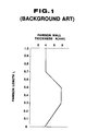
- Japanese Patent First (Unexamined) Publication (Tokkaisho) No. 63-82707 discloses one of the conventional parison thickness control system.
- desired parison wall thickness A is defined over the entire longth L of the parison in the form of a broken line, which data is stored in the memory unit.
- the system derives a target parison wall thickness A for a corresponding parison length per unit time during the parison extrusion or forming cycle based on the stored data using the method of interpolation, and adjusts an annular gap between the extruder die and a core of the mandrel according to a value of the derived target parison wall thickness A.
- the system sequentially derives a parison length which is to be extruded during the unit time based on the derived target parison wall thickness A and an extrusion amount of the melted plastic.
- the system further derives the accumulated parison length sequentially for deriving the corresponding target parison thickness A using the above-noted stored data and for detecting the termination of the parison extrusion cycle by comparing it with the stored entire parison length L.
- the termination of the parison extrusion cycle may also be detected by comparing an accumulated elapsed time with the stored entire parison extrusion cycle time.
- the parison thickness control system can not control operations of other associated devices in the plastic molding machine in timed synchronism with the parison extrusion cycle.
- the timed synchronism between the parison extrusion cycle and the entire operation cycle of the plastic molding machine including, such as, the closing and opening of a mold having two mold halves, the cutting of the parison by a parison cutter and the transfer of the mold to another station, should be necessary.
- a parison thickness control system including an extruder die and a mandrel, the extruder die and the mandrel being movable relative to each other to change wall thickness of a parison extruded between the extruder die and the mandrel during an extrusion cycle of the parison, comprises: manually data input means for inputting a plurality of master points, each of the master points defined in terms of a target thickness of the parison and an elapsed time during the parison extrusion cycle; first means for performing the spline interpolation so as to interpolate between the input master points to derive a first parison control pattern; second means for correcting the first parison control pattern so as to allow the maximum or minimum value of the master points to indicate a limit value for the target thickness of the parison during the parison extrusion cycle for deriving a second parison control pattern; third means for setting cycle
- a parison thickness control method in which a gap defined between a die and a mandrel is adjusted by gap adjusting means so as to control thickness of a parison extruded through the gap, comprises the steps of: defining a parison forming time and a target parison thickness value on two axes intersecting in perpendicular to each other; setting master points at a plurality of points which are determined by considering a thickness variation of the parison; forming a pattern by interpolating between the master points using the method of spline interpolation and further by interpolating to make the maximum or minimum value of the master points a limit value; setting cycle points which divide a parison forming cycle time into a predetermined number of equal time intervals; deriving a target parison thickness value for a corresponding parison forming time per each of the cycle points using the pattern; controlling a position of the mandrel so as to provide the derived target parison thickness value.
- a parison thickness control method in which a gap defined between a die and a mandrel is adjusted by gap adjusting means so as to control thickness of a parison extruded through the gap, comprises the steps of: forming a pattern by defining a parison forming time and a target parison thickness value on two axes intersecting in perpendicular to each other; presetting positions of the mandrel corresponding to the target parison thickness value, and a parison forming cycle time; setting cycle points which divide the parison forming cycle time into a predetermined number of equal time intervals; controlling the position of the mandrel based on the target parison thickness value for each cycle point; outputting an operation signal to an associated device constituting a part of the entire molding process of a product at least at one of the cycle points so as to provide timed synchronism between the parison forming and the product molding.
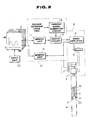
- Fig. 2 shows an entire structure of the parison wall thickness control system according to the first preferred embodiment.
- an extruder die 1 has an opening which receives therein a mandrel 2.
- the mandrel 2 has a stem portion 2a and a core portion 2b having a conical shape.
- the stem portion 2a is mechanically connected to a hydraulic cylinder 3 at its upper end and is continuous with the core portion 2b at its lower end, so that a vertical position of the core portion 2b relative to the extruder die 1 is adjustable by the operation of the hydaulic cylinder 3.
- An annular flow passage f is formed between the stem portion 2a of the mandrel 2 and cylindrical walls of the extruder die opening, and an annular funnel-shaped flow passsage or gap g is formed between the core portion 2b of the mandrel 2 and diverging walls of the extruder die opening.
- a melted plastic is introduced downward from a body of the parison extruder through the flow passages f and g so as to form a parison 4 which is introduced into a mold cavity of a mold having two mold halves and expands by means of introduced gas under pressure into complete contact with the walls of the mold cavity as shown in Fig. 6.
- a width of the flow passage or gap g is adjustable by changing the vertical position of the mandrel core portion 2b so as to adjust wall thickness of the extruded parison 4 as desired.
- the operation of the hydraulic cylinder 3 is controlled by a hydraulic servo valve 5 which controls the application of pressurized fluid to the hydraulic cylinder 3 based on signals from a servo amplifier 6.
- the servo amplifier 6 receives a control signal from a machine controller which will be described later and a feedback signal indicative of the position of the mandrel 2 from a position sensor 7 such as a potentiometer, and feeds the signal to the hydraulic cylinder 3 in the form of an error signal indicative of a difference between the control signal and the feedback signal.
- the hydraulic cylinder 3, the hydraulic servo valve 5, the servo amplifier 6 and the position sensor 7 cooperatively constitute a flow width or gap adjusting means 8 which adjusts the width of the flow passage or gap g.
- the operation of the gap adjusting means 8 is controlled by the control signals from the machine controller 10.
- the machine controller 10 includes a memory unit 11 which stores a parison control pattern representative of target parison wall thickness over the entire length of the extruded parison 4, and a periodic signal generating circuit 13 which outputs a predetermined number N of signals during a parison extrusion or forming cycle so as to divide the parison extrusion cycle into the number N of equal time intervals or increments.
- the occurrences of the periodic signals respectively correspond to cycle points which are set in the above-noted parison control pattern stored in the memory unit 11 and will be described later in detail.
- the machine controller 10 further includes an output circuit 12 which receives the periodic signals from the periodic signal generating circuit 13 and outputs the control signal to the servo amplifier 6 per every cycle point.
- the control signal is a positional signal indicative of a magnitude of stroke of the mandrel 2 or its core portion 2b.
- the magnitude of the mandrel stroke is derived based on the target parison wall thickness which is read out per every cycle point from the stored parison control pattern triggered by the periodic signal.
- the machine controller further includes a monitor unit 14 which receives the feedback signal from the position sensor 7 and a signal from a pattern monitor unit 21 to monitor the actual controlled state of, such as, the movement of the mandrel 2 or its core portion 2b.
- a reference numeral 20 denotes a data input unit for manually inputting master points to provide a provisional parison control pattern representative of the target parison wall thickness in terms of parison forming times or parison extrusion elapsed times during the parison extrusion cycle.
- the pattern monitor unit 21 includes cathode ray tubes (CRT) for displaying the above-noted parison control patterns when forming them and for displaying the controlling state for the parison extrusion.
- CTR cathode ray tubes
- a finished bottle product 40 is shown as being in the mold 41.
- the extruded parison 4 is expanded by means of the intruduced gas under pressure so as to get in complete contact with the walls of the mold cavity.
- only one mold half is shown in Fig. 6.
- Fig. 5 shows the parison control pattern derived according to the first preferred embodiment for molding the finished bottle product 40 as shown in Fig. 6.
- the parison control pattern is defined by target parison wall thickness on an X-axis and parison forming time or parison extrusion elapsed time in the parison extrusion cycle on a Y-axis.
- the Y-axis represents rate (%) of elapsed time relative to the entire parison extrusion cycle, i.e.
- the parison extrusion cycle executing rate (%) which corresponds to the overall length L of the extruded parison 4, and the X-axis represents rate (%) of target parison wall thickness relative to the maximum thickness w which can be provided with the mandrel at its adjustable lowermost position, i.e. the parison wall thickness executing rate (%).
- the parison control pattern is formed considering the configuration and the required thickness of the finished product 40 and accordingly is variable depending on the characteristics of the finished product 40.
- the parison control pattern is formed by first setting a plurality of the master points (ten master points in the preferred embodiments) mp1 to mp10 each corresponding to a portion of the extruded parison 4 where variation in the wall thickness is necessary.
- the master points are variably set according to the characteristics of the finished product.
- the method of the spline interpolation which is well known, is performed to interpolate between the master points so as to derive a dotted line B.
- correction of the line B is performed such that when a curved line on which the maximum or minimum value of the master points is not a limit value, the correction is made to make zero an inclination of the line B at that maximum or minimum value of the master points.
- the correction is made to connect those adjacent target points by a straight line.
- the spline interpolation is corrected to derive a smooth curved line A indicated by a solid line.
- the parison extrusion cycle is divided into 100 equal time intervals, 100 cycle points are set for equal time intervals each of 1/100 time of the parison extrusion cycle, and a target parison wall thickness is derived for each cycle point using the parison control pattern defined by the line A and is stored in the memory unit 11 as the final matrix data.
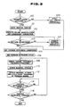
- Fig. 3 shows the control flowchart to be executed in the machine controller 10.
- a desired parison control pattern is set either based on the interpolated line or by inputting all points manually, one of which is selected at a step 100.
- the parison control pattern is set based on the interpolated line. If answer at the step 100 is NO, then all necessary points are input manually at a step 1001. On the other hand, if answer at the step 100 is YES, then the master points mp1 to mp10 are input manually at a step 101 using the data input unit 20.
- the dotted line B as shown in Fig. 5 is first derived by the spline interpolation, and subsequently, the further interpolation or correction is performed to correct the maximum or minimum value of the master points to be a limit value so as to derive the line A which is a smooth curved line with no protruded portion.
- a subsequent step 103 it is manually decided whether the parison control pattern derived at the step 102 is correct or desirable. If answer at the step 103 is NO, i.e. modification is necessary to the derived parison control pattern, then the modification is performed manually using the data input unit 20. On the other hand, if answer at the stop 103 is YES, then the process goes to a step 104 where parison forming or extrusion conditions, such as, a stroke of the mandrel 2 or its core portion 2b are set, which stroke of the mandrel 2 provides the maximum parison wall thickness w, i.e. which stroke corresponds to the wall thickness execution rate being 100%. Subsequently, the parison extrusion or forming cycle time is set at the step 106.
- parison forming or extrusion conditions such as, a stroke of the mandrel 2 or its core portion 2b are set, which stroke of the mandrel 2 provides the maximum parison wall thickness w, i.e
- the data derived at the step 102 or set at the step 1001, and set at the steps 104 and 106 are input into the pattern monitor unit 21 and stored in the memory unit 11.
- a target parison wall thickness is derived for each cycle point, and then at a step 110, a corresponding stroke of the mandrel 2 or its core portion 2b is derived based on each target parison wall thickness derived at the step 108.
- the control signal indicative of the mandrel or core portion stroke derived at the step 110 is output from the output circuit 12 to the servo amplifier 6, triggered by the periodic signal from the periodic signal generating circuit 13, which periodic signal is generated at a timing corresponding to each cycle point and divides the entire parison extrusion cycle into the predetermined number N, i.e. 100 in the preferred embodiments.
- the servo amplifier 6 in turn controls the operation of the hydraulic cylinder 3 through the hydraulic servo valve 5 so as to adjust the position of the mandrel 2 or its core portion 2b corresponding to the control signal indicative of the mandrel or core portion stroke. Specifically, the position of the mandrel 2 or its core portion 2b is monitored by the position sensor 7 which feeds the feedback signal to the servo amplifier 6. The servo amplifier 6 outputs to the servo valve 5 an error signal indicative of a difference between the control signal and the feedback signal so as to adjust the position of the mandrel 2 or its core portion 2b corresponding to the control signal.
- the feedback signal is simultaneously fed to the monitor unit 14 of the machine controller 10 for monitoring the actual behaviour of the mandrel 2 or its core portion 2b.
- step 114 it is checked whether the parison extrusion or forming cycle time is over or passed.
- the parison extrusion cycle is started with the cycle point "zero" and is finished with the cycle point "N-1".
- the wall thickness pattern of the extruded parison 4 follows the solid line A as shown in Fig. 5. Accordingly, the finished product having no discontinuous portions, such as, ring lines and no unexpected unevenness in thickness can be molded with the optimum wall thickness.
- the number of the cycle points may be set greater, for example, at the number of 200, so that the wall thickness pattern of the extruded parison more precisely follows the solid line A in Fig. 5. Further, the number of the master points may also be set larger depending on the characteristics, such as, the configuration and the required wall thickness of the finished product.
- the foregoing preferred embodiment makes it possible to modify or change a target parison wall thickness partially, i.e. at a desired portion of the parison. Still further, the foregoing preferred embodiment makes it possible to change only the entire parison extrusion cycle time if desired, so as to provide the corresponding wall thickness pattern of the parison. Further, in Fig. 3, though the process returns to the step 108 when answer at the step 116 is NO, the process may return to the step 112 when forming a parison having the same configuration by storing the data derived at the steps 108 and 110.
- the parison 4 extruded through the flow passages f and g in the first preferred embodiment is sequentially cut at a predetermined constant length L by a parison cutter (not shown) to be transferred, being held in the mold cavity, to a next station, such as, a blow station to be expanded into complete contact with the walls of the mold cavity so as to be formed into the finished mold product.
- a parison cutter not shown
- the parison extrusion cycle should be in timed synchronims with the operations of the other associated devices, such as, the closing of the mold, the cutting of the parison by the parison cutter and the transfer of the mold to the next station.
- the setting of the timings among the above-noted operations is quite important for preventing dislocation of the wall thickness variation so as to ensure the extruded parison having a desired (uniform) wall thickness distribution, which leads to the finished product having a desired wall thickness pattern.
- operation signals are fed to the associated devices at timings of predetermined cycle points, which will be described hereinbelow with reference to the flowchart as shown in Fig. 4.
- the parison control pattern is determined at a first step 200, and the parison extrusion cycle time is set at a subsequent step 202.
- the operation timings such as, the mold closing, the cutting of the parison by the parison cutter and the transfer of the mold to the next station are respectively set in sychronism with the corresponding cycle points.
- each of the above-noted timings is set at a corresponding one of 100 cycle points.
- the parison extrusion is started at a step 206.
- the parison wall thickness control is executed from the cycle point "zero" at a subsequent step 208.
- the operation signal is output to the corresponding device to start the operation thereof, at a step 210.
- the parison extrusion cycle time is T(sec)
- the cycle point for starting the operation of a predetermined device is set to the number P
- a total number of the cycle points is set to N
- a required time from the cycle point "zero" to the preset cycle point P is t(sec)
- N 100
- T 5(sec)
- P 40
- t becomes 2(sec).
- the number of the cycle points i.e. of the periodic signals are counted by a counter from a time point of the start of the parison extrusion so that the corresponding associated device is operated when a counter value reaches the number P.
- the termination of the preset parison extrusion cycle time is detected at a step 212 when the number of the cycle point, i.e.
- step 214 checks whether the parison extrusion is finished. If answer at the step 214 is NO, i.e. the parison extrusion is not yet finished, then the counter value is reset to zero, and the process returns to the step 208.
- the wall thickness pattern of the parison 4 extruded through the flow passages f and g precisely follows the solid line A as shown in Fig. 5. Further, since the operations of the associated devices are respectively in timed synchronism with the parison extrusion cycle, the dislocation of the parison wall thickness variation is effectively prevented to ensure the desired wall thickness distribution in the finished product.
- the number of the cycle point P is variably set depending on the characteristics of the corresponding associated device.
- the spline interpolation and the subsequent correction may be replaced with other method as long as a predetermined cycle point is used to control the operation of the associated device.
- the mandrel or its core portion is designed to shift relative to the extruder die so as to vary the width of the flow passage or gap g
- the extruder die may be alternatively shifted relative to the mandrel or its core portion so as to vary the width of the flow passage or gap g.
Landscapes
- Engineering & Computer Science (AREA)
- Mechanical Engineering (AREA)
- Manufacturing & Machinery (AREA)
- Blow-Moulding Or Thermoforming Of Plastics Or The Like (AREA)
Applications Claiming Priority (4)
| Application Number | Priority Date | Filing Date | Title |
|---|---|---|---|
| JP55759/90 | 1990-03-07 | ||
| JP2055759A JPH03256706A (ja) | 1990-03-07 | 1990-03-07 | パリソン肉厚制御方法 |
| JP62204/90 | 1990-03-13 | ||
| JP6220490A JPH03262606A (ja) | 1990-03-13 | 1990-03-13 | パリソン肉厚制御方法 |
Publications (2)
| Publication Number | Publication Date |
|---|---|
| EP0445774A1 true EP0445774A1 (de) | 1991-09-11 |
| EP0445774B1 EP0445774B1 (de) | 1995-01-25 |
Family
ID=26396656
Family Applications (1)
| Application Number | Title | Priority Date | Filing Date |
|---|---|---|---|
| EP91103411A Expired - Lifetime EP0445774B1 (de) | 1990-03-07 | 1991-03-06 | System und Verfahren zum Regeln der Wandstärke von Vorformlingen |
Country Status (3)
| Country | Link |
|---|---|
| US (1) | US5198161A (de) |
| EP (1) | EP0445774B1 (de) |
| DE (1) | DE69106906T2 (de) |
Cited By (4)
| Publication number | Priority date | Publication date | Assignee | Title |
|---|---|---|---|---|
| EP0611700A1 (de) * | 1993-02-19 | 1994-08-24 | Fuji Photo Film Co., Ltd. | Flüssigkeitsbehälter |
| WO2004078456A1 (en) * | 2003-03-04 | 2004-09-16 | Davis-Standard Corporation | A controller for bypassing a pressure-reducing valve in a blow-molding machine and method thereof |
| US7160099B2 (en) | 2003-09-02 | 2007-01-09 | Davis-Standard, Llc | Leakage-free feed roll assembly for an extruder machine |
| DE102006018883A1 (de) * | 2006-04-24 | 2007-10-25 | Ossberger Gmbh + Co. | Verfahren und Vorrichtung zum Herstellen eines schlauchartigen Gegenstands aus thermoplastischem Kunststoff |
Families Citing this family (7)
| Publication number | Priority date | Publication date | Assignee | Title |
|---|---|---|---|---|
| JP2898197B2 (ja) * | 1993-06-18 | 1999-05-31 | キヤノン株式会社 | 光学素子及びその成形方法及びレーザー走査光学系 |
| US6405887B1 (en) | 1998-12-16 | 2002-06-18 | Graham Packaging Company, L.P. | Blow-molded container having reinforcement ribs and method and apparatus for making same |
| US6922606B1 (en) | 1999-11-19 | 2005-07-26 | Siemens Energy & Automation, Inc. | Apparatus and method for smooth cornering in a motion control system |
| US7738993B2 (en) * | 2003-10-10 | 2010-06-15 | Boston Scientific Scimed, Inc. | Extrusion of articles |
| EP1675904B1 (de) * | 2003-10-22 | 2011-04-06 | The Procter & Gamble Company | Zusammensetzung in kombination mit einer extrusionsblasgeformten thermoplastischen packung |
| US7953513B2 (en) * | 2005-03-15 | 2011-05-31 | Siemens Industry, Inc. | Systems, devices, and methods for automation control |
| DE102008052608B3 (de) * | 2008-10-21 | 2010-05-20 | Feuerherm, Harald, Dipl.-Ing. | Verfahren zur Herstellung von Kunststoffhohlkörpern durch Blasformen |
Citations (4)
| Publication number | Priority date | Publication date | Assignee | Title |
|---|---|---|---|---|
| DE1934284A1 (de) * | 1969-07-07 | 1971-02-04 | Indramat Gmbh | Vorrichtung zum Regeln der Wandstaerke des Extrudates von Kunststoffmaschinen |
| US4424178A (en) * | 1981-01-23 | 1984-01-03 | Krupp Kautex Machinenbau GmbH | Procedure and device for production of a preform of thermoplastic synthetic material by means of extrusion |
| JPS6382707A (ja) * | 1986-09-29 | 1988-04-13 | Japan Steel Works Ltd:The | パリソン肉厚制御方法 |
| GB2221642A (en) * | 1988-07-14 | 1990-02-14 | Harcostar Ltd | Regulating the wall thickness of an extruding parison |
Family Cites Families (7)
| Publication number | Priority date | Publication date | Assignee | Title |
|---|---|---|---|---|
| US3474160A (en) * | 1965-04-27 | 1969-10-21 | Industrial Nucleonics Corp | Method and apparatus for controlling blown film extruder |
| US3865528A (en) * | 1973-11-01 | 1975-02-11 | Moog Inc | Extrusion apparatus having electronic interpolator |
| DE2816583A1 (de) * | 1978-04-17 | 1979-10-18 | Windmoeller & Hoelscher | Verfahren und vorrichtung zur optimierung der ausstossleistung einer blasfolienextruderanlage mittels eines prozessrechners |
| US4623238A (en) * | 1983-02-01 | 1986-11-18 | Minolta Camera Kabushiki Kaisha | Camera system capable of automatic focus control |
| US4663726A (en) * | 1985-04-15 | 1987-05-05 | General Electric Co. | Robot control utilizing cubic spline interpolation |
| JPH0782554B2 (ja) * | 1986-09-10 | 1995-09-06 | フアナツク株式会社 | 曲面加工方法 |
| JPH02113305A (ja) * | 1988-10-24 | 1990-04-25 | Fanuc Ltd | スプライン補間方法 |
-
1991
- 1991-03-05 US US07/664,823 patent/US5198161A/en not_active Expired - Lifetime
- 1991-03-06 DE DE69106906T patent/DE69106906T2/de not_active Expired - Fee Related
- 1991-03-06 EP EP91103411A patent/EP0445774B1/de not_active Expired - Lifetime
Patent Citations (4)
| Publication number | Priority date | Publication date | Assignee | Title |
|---|---|---|---|---|
| DE1934284A1 (de) * | 1969-07-07 | 1971-02-04 | Indramat Gmbh | Vorrichtung zum Regeln der Wandstaerke des Extrudates von Kunststoffmaschinen |
| US4424178A (en) * | 1981-01-23 | 1984-01-03 | Krupp Kautex Machinenbau GmbH | Procedure and device for production of a preform of thermoplastic synthetic material by means of extrusion |
| JPS6382707A (ja) * | 1986-09-29 | 1988-04-13 | Japan Steel Works Ltd:The | パリソン肉厚制御方法 |
| GB2221642A (en) * | 1988-07-14 | 1990-02-14 | Harcostar Ltd | Regulating the wall thickness of an extruding parison |
Cited By (7)
| Publication number | Priority date | Publication date | Assignee | Title |
|---|---|---|---|---|
| EP0611700A1 (de) * | 1993-02-19 | 1994-08-24 | Fuji Photo Film Co., Ltd. | Flüssigkeitsbehälter |
| US5573129A (en) * | 1993-02-19 | 1996-11-12 | Fuji Photo Film Co., Ltd. | Collapsible container for a liquid |
| WO2004078456A1 (en) * | 2003-03-04 | 2004-09-16 | Davis-Standard Corporation | A controller for bypassing a pressure-reducing valve in a blow-molding machine and method thereof |
| US7179073B2 (en) | 2003-03-04 | 2007-02-20 | Davis-Standard, Llc | Pressure-reducing valve and a controller for a blow-molding machine and method thereof |
| US7160099B2 (en) | 2003-09-02 | 2007-01-09 | Davis-Standard, Llc | Leakage-free feed roll assembly for an extruder machine |
| DE102006018883A1 (de) * | 2006-04-24 | 2007-10-25 | Ossberger Gmbh + Co. | Verfahren und Vorrichtung zum Herstellen eines schlauchartigen Gegenstands aus thermoplastischem Kunststoff |
| US8357326B2 (en) | 2006-04-24 | 2013-01-22 | Ossberger Gmbh & Co. | Method and device for producing a tubular object from thermoplastic material |
Also Published As
| Publication number | Publication date |
|---|---|
| EP0445774B1 (de) | 1995-01-25 |
| US5198161A (en) | 1993-03-30 |
| DE69106906D1 (de) | 1995-03-09 |
| DE69106906T2 (de) | 1995-05-24 |
Similar Documents
| Publication | Publication Date | Title |
|---|---|---|
| EP0445774B1 (de) | System und Verfahren zum Regeln der Wandstärke von Vorformlingen | |
| US4444702A (en) | Method and apparatus for producing extruded sections of thermoplastic material | |
| US7691317B2 (en) | Method and device for manufacturing a double-walled, thermoplastic tube with a connecting sleeve | |
| US4338071A (en) | Apparatus for the manufacture of hollow bodies from a thermoplastic by the blow-moulding process | |
| US4189288A (en) | Apparatus for producing blown synthetic-resin foils and films | |
| US5102588A (en) | Method of controlling the position of an extruded preform in a blow mold | |
| US4424178A (en) | Procedure and device for production of a preform of thermoplastic synthetic material by means of extrusion | |
| US4559991A (en) | Method and system of controlling injection molding machines | |
| GB1565855A (en) | Multiple extrusion head extrusion blow moulding apparatus and multiple extrusion head therefor | |
| GB2178361A (en) | Blow moulding | |
| US8357326B2 (en) | Method and device for producing a tubular object from thermoplastic material | |
| US5567368A (en) | Extrusion molding method and extrusion molding apparatus | |
| US3936713A (en) | Machine control circuit | |
| JP2979323B2 (ja) | 制御信号発生用電気的制御装置 | |
| JPH0530603B2 (de) | ||
| JPH01278325A (ja) | ブロー成形機 | |
| JP2795292B2 (ja) | ブロー成形機のパリソン肉厚制御方法および装置 | |
| JPH0788945A (ja) | パリソンの肉厚制御方法 | |
| JPS62202712A (ja) | パリスンの押出方法及びその装置 | |
| JPH0530604B2 (de) | ||
| JPH0788946A (ja) | パリソンの肉厚制御方法 | |
| JP3028903B2 (ja) | パリソンの肉厚制御方法 | |
| JPH0684037B2 (ja) | 押出機等の制御方法 | |
| JP3028910B2 (ja) | パリソンの肉厚制御方法 | |
| JP3036665B2 (ja) | パリソンの肉厚制御方法 |
Legal Events
| Date | Code | Title | Description |
|---|---|---|---|
| PUAI | Public reference made under article 153(3) epc to a published international application that has entered the european phase |
Free format text: ORIGINAL CODE: 0009012 |
|
| 17P | Request for examination filed |
Effective date: 19910306 |
|
| AK | Designated contracting states |
Kind code of ref document: A1 Designated state(s): DE FR IT |
|
| 17Q | First examination report despatched |
Effective date: 19930729 |
|
| GRAA | (expected) grant |
Free format text: ORIGINAL CODE: 0009210 |
|
| AK | Designated contracting states |
Kind code of ref document: B1 Designated state(s): DE FR IT |
|
| REF | Corresponds to: |
Ref document number: 69106906 Country of ref document: DE Date of ref document: 19950309 |
|
| ITF | It: translation for a ep patent filed | ||
| ET | Fr: translation filed | ||
| PLBE | No opposition filed within time limit |
Free format text: ORIGINAL CODE: 0009261 |
|
| STAA | Information on the status of an ep patent application or granted ep patent |
Free format text: STATUS: NO OPPOSITION FILED WITHIN TIME LIMIT |
|
| 26N | No opposition filed | ||
| PGFP | Annual fee paid to national office [announced via postgrant information from national office to epo] |
Ref country code: FR Payment date: 20060313 Year of fee payment: 16 |
|
| PGFP | Annual fee paid to national office [announced via postgrant information from national office to epo] |
Ref country code: IT Payment date: 20060331 Year of fee payment: 16 |
|
| PGFP | Annual fee paid to national office [announced via postgrant information from national office to epo] |
Ref country code: DE Payment date: 20060530 Year of fee payment: 16 |
|
| REG | Reference to a national code |
Ref country code: FR Ref legal event code: ST Effective date: 20071130 |
|
| PG25 | Lapsed in a contracting state [announced via postgrant information from national office to epo] |
Ref country code: DE Free format text: LAPSE BECAUSE OF NON-PAYMENT OF DUE FEES Effective date: 20071002 |
|
| PG25 | Lapsed in a contracting state [announced via postgrant information from national office to epo] |
Ref country code: FR Free format text: LAPSE BECAUSE OF NON-PAYMENT OF DUE FEES Effective date: 20070402 |
|
| PG25 | Lapsed in a contracting state [announced via postgrant information from national office to epo] |
Ref country code: IT Free format text: LAPSE BECAUSE OF NON-PAYMENT OF DUE FEES Effective date: 20070306 |