EP0445908B1 - Method and apparatus for interrupting fluid streams - Google Patents
Method and apparatus for interrupting fluid streams Download PDFInfo
- Publication number
- EP0445908B1 EP0445908B1 EP91300353A EP91300353A EP0445908B1 EP 0445908 B1 EP0445908 B1 EP 0445908B1 EP 91300353 A EP91300353 A EP 91300353A EP 91300353 A EP91300353 A EP 91300353A EP 0445908 B1 EP0445908 B1 EP 0445908B1
- Authority
- EP
- European Patent Office
- Prior art keywords
- fluid
- stream
- channel
- passage
- open channel
- Prior art date
- Legal status (The legal status is an assumption and is not a legal conclusion. Google has not performed a legal analysis and makes no representation as to the accuracy of the status listed.)
- Expired - Lifetime
Links
- 239000012530 fluid Substances 0.000 title claims abstract description 128
- 238000000034 method Methods 0.000 title claims abstract description 20
- 239000007788 liquid Substances 0.000 claims description 15
- 239000000758 substrate Substances 0.000 claims description 14
- 239000004753 textile Substances 0.000 claims description 5
- 238000004891 communication Methods 0.000 claims description 3
- 238000011144 upstream manufacturing Methods 0.000 claims description 2
- XLYOFNOQVPJJNP-UHFFFAOYSA-N water Substances O XLYOFNOQVPJJNP-UHFFFAOYSA-N 0.000 description 5
- 230000008569 process Effects 0.000 description 3
- 230000004044 response Effects 0.000 description 3
- 239000007789 gas Substances 0.000 description 2
- 238000004519 manufacturing process Methods 0.000 description 2
- 238000000059 patterning Methods 0.000 description 2
- 230000009471 action Effects 0.000 description 1
- 238000013459 approach Methods 0.000 description 1
- 230000008859 change Effects 0.000 description 1
- 238000004140 cleaning Methods 0.000 description 1
- 230000002950 deficient Effects 0.000 description 1
- 230000000694 effects Effects 0.000 description 1
- 239000004744 fabric Substances 0.000 description 1
- PCHJSUWPFVWCPO-UHFFFAOYSA-N gold Chemical compound [Au] PCHJSUWPFVWCPO-UHFFFAOYSA-N 0.000 description 1
- 239000010931 gold Substances 0.000 description 1
- 229910052737 gold Inorganic materials 0.000 description 1
- 238000010348 incorporation Methods 0.000 description 1
- 238000007689 inspection Methods 0.000 description 1
- 230000001788 irregular Effects 0.000 description 1
- 238000012423 maintenance Methods 0.000 description 1
- 239000002184 metal Substances 0.000 description 1
- 229910052751 metal Inorganic materials 0.000 description 1
- 239000003595 mist Substances 0.000 description 1
- 230000035515 penetration Effects 0.000 description 1
- 230000035484 reaction time Effects 0.000 description 1
- 230000007480 spreading Effects 0.000 description 1
- 238000003892 spreading Methods 0.000 description 1
- 229910001220 stainless steel Inorganic materials 0.000 description 1
- 239000010935 stainless steel Substances 0.000 description 1
- 238000012360 testing method Methods 0.000 description 1
- 230000000007 visual effect Effects 0.000 description 1
Images

Classifications
-
- D—TEXTILES; PAPER
- D06—TREATMENT OF TEXTILES OR THE LIKE; LAUNDERING; FLEXIBLE MATERIALS NOT OTHERWISE PROVIDED FOR
- D06B—TREATING TEXTILE MATERIALS USING LIQUIDS, GASES OR VAPOURS
- D06B11/00—Treatment of selected parts of textile materials, e.g. partial dyeing
- D06B11/0056—Treatment of selected parts of textile materials, e.g. partial dyeing of fabrics
- D06B11/0059—Treatment of selected parts of textile materials, e.g. partial dyeing of fabrics by spraying
-
- D—TEXTILES; PAPER
- D04—BRAIDING; LACE-MAKING; KNITTING; TRIMMINGS; NON-WOVEN FABRICS
- D04H—MAKING TEXTILE FABRICS, e.g. FROM FIBRES OR FILAMENTARY MATERIAL; FABRICS MADE BY SUCH PROCESSES OR APPARATUS, e.g. FELTS, NON-WOVEN FABRICS; COTTON-WOOL; WADDING ; NON-WOVEN FABRICS FROM STAPLE FIBRES, FILAMENTS OR YARNS, BONDED WITH AT LEAST ONE WEB-LIKE MATERIAL DURING THEIR CONSOLIDATION
- D04H18/00—Needling machines
- D04H18/04—Needling machines with water jets
Definitions
- This invention relates to a method and apparatus for forming one or more fluid streams having relatively small, well defined cross sectional areas, and for interrupting, selectively and repeatedly, the floe of such streams in response to an externally supplied signal. More specifically, this invention relates to a method and apparatus which may be used to form and pulse the flow of one or more such fluid stream wherein the fluid streams must be directed onto a target of substrate with a precision on the order of 0.254mm (0.010 inch), and wherein the stream are being formed with fluid at pressures up to or exceeding 20MPa (300 p.s.i.g.).
- the invention disclosed herein is suitable for use with both gases and liquids, at a variety of pressures, but is particularly well suited for applications wherein a liquid is to be formed and controlled.
- the teachings of this invention are especially well suited to application wherein (1) fine liquid streams are formed having precisely defined cross sections, (2) such streams must be directed at a target with a high degrees of accuracy and precision, and (3) such streams must be repeatedly and selectively interrupted and re-established, possibly over irregular or extended time intervals, with an extremely fast "on-off-on" response characteristic, in accordance with electronically defined and carried commands, and with relatively, small expenditures os switching energy.
- teachings of this invention may be used advantageously in a wide variety of practical applications where fine stream of fluid are formed and/or applied to a target in a noncontinuous manner, and where the streams are desirably interruptible in accordance with computer-supplied commands or data.
- Such applications are disclosed, for example, in US Patent No 3,443,878 to Weber, et al., as well as US Patent No 3,942,343 to Klein.
- These processes relate to the projection of several liquid streams of dye onto a textile substrate, and diverting one or more of the streams from a path leading to the substrate into a sump in accordance with externally supplied pattern information.
- These applications and processes are also disclosed in FR-A-2,588,199. It is believed that the teachings of this invention could improve significantly the degree of definition achievable with these systems as disclosed, as well as improve the deflection energy efficiency and perhaps improve the extent of dye penetration or degree of visual contrast achieved with such systems.
- the method and apparatus of this invention may be used in the field of graphic arts for the purpose of controlling a fine stream of ink and selectively projecting the stream onto a paper target in accordance with electronically generated text or graphic commands.
- a method for intermittently interrupting the flow of a first fluid stream within an open channel, which stream at least partially conforms to and is laterally confined within said open channel, thereby defining the lateral boundaries of said stream, by means of a transverse stream of a second fluid said method comprising directing from a source a transverse stream of a second fluid into said first fluid stream with sufficient pressure to force said first fluid stream to leave the confines of said channel characterised by redirecting a portion of the first fluid from the source of the second fluid when there is no second pressured fluid in the source wherein the redirected first fluid is directed along an arcuate surface.
- an apparatus for intermittently interrupting the flow of a first fluid stream within an open channel, which stream at least partially conforms to and is laterally confined within said open channel, thereby laterally restricting said stream to the confines of said channel, by means of a transverse stream of a second fluid said means comprising means for supplying a stream of said first fluid in alignment with said channel, means for directing a transverse stream of said second fluid into said first fluid stream and fluid supply means for supplying said second fluid to said directing means at a sufficient pressure to cause said first fluid stream to leave the confines of said channel, said means for directing a transverse stream of said fluid including a passage in communication with said channel, said passage characterised by having an arcuate-shaped outlet into said channel downstream from the means to supply said first fluid to redirect portions of said first fluid therein back to said channel.
- an apparatus to apply selective streams of a fluid onto a substrate comprising a first conduit means to supply a first fluid under pressure onto a substrate, a second conduit means operably associated with said first means to supply a fluid under pressure against the first fluid under pressure at predetermined times to direct the first fluid away from the substrate and means to periodically supply the second fluid against the first fluid, characterised by said second conduit means having a sharp portion adjacent the upstream side of said first conduit means and an arcuate portion adjacent the downstream portion of said first conduit means.
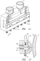
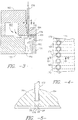
- Figures 1 through 5 depict an apparatus, embodying the instant invention, which may be used for the purpose of forming and interrupting the flow of a fluid stream in an open channel.
- This apparatus may, if desired, be used to interrupt intermittently the flow of a high pressure liquid stream, but is by no means limited to such application.
- Low pressure liquid streams, as well as gas streams at various velocities, may be selectively interrupted using the teachings herein. For purposes of the discussion which follows, however, it will be assumed that the fluid stream flowing in the channel is a liquid at relatively high velocity.
- a conduit 10A supplies, via filter 71 ( Figure 1), a high pressure working fluid to manifold cavity 162 formed within inlet manifold block 160.
- Flange 164 is formed along one side of manifold block 160; into the base of flange 164 is cut a uniformly spaced series of parallel channels or grooves 166.
- Each groove 166 extends from cavity 162 to the forward-most edge of flange 164 and has cross-sectional dimensions corresponding to the desired cross-sectional dimensions of the stream.
- the groove may have a cross-section resembling the letter "U", or may have a totally arbitrary shape.
- Control tubes 170 through which streams of relatively low pressure air or other control fluid are passed on command, are arranged in one-to-one relationship with grooves 166, and are, in one embodiment, positioned substantially in alignment with and perpendicular to grooves 166 by means of a series of sockets or wells 172 in flange 164, each of which are placed in direct vertical alignment with a respective groove 166 in flange 164, and into which each tube 170 is securely fastened.
- the floor of each socket 172 has a small passage 174 which in turn communicates directly with the base of its respective groove 166.
- outlet manifold block 180 and optional containment plate 178 Positioned opposite inlet manifold block 160 and securely abutted thereto via bolts 161 are outlet manifold block 180 and optional containment plate 178. Containment plate 178 may be attached to outlet manifold block 180 by means of screws 179 or other suitable means.
- outlet manifold block 180 Within outlet manifold block 180 is machined optional discharge cavity 182 and outlet drain 184. Discharge cavity 182 and outlet drain 184 may extend across several grooves 166 in flange 164, or individual cavities and outlets for each groove 166 may be provided. It is preferred, however, that cavity 182 be positioned so that passage 174 leads directly into cavity 182, and not led into the upper surface of outlet manifold block 180 or containment plate 178.
- Discharge cavity 182 includes impact cavity 177 which is machined into containment plate 178.
- Bolts 183 and 185 provide adjustment of the relative alignment between inlet manifold block 160 and the combination of outlet manifold block 180 and containment plate
- a working fluid is fed into inlet cavity 162, where it is forced to flow through a first enclosed passage, formed by grooves 166 in flange 164 and the face of outlet manifold block 180 opposite flange 164, thereby forming the fluid into discrete streams having the desired cross-sectional shape and area.
- the pre-formed streams may be positioned within grooves 166 so that reduced or substantially no contact between the streams and the floor or base of grooves 166 occurs, and that substantially all contact between the streams and the grooves takes place at the groove walls, which walls thereby define the lateral boundaries of the streams.
- the streams of working fluid may be made to traverse the width of discharge cavity 182 in an open channel formed only by grooves 166 without a significant loss in the coherency or change in the cross-sectional shape or size of the stream, although under certain conditions, some slight spreading of the stream in a direction parallel to the groove walls and normal to the groove floor may occur.
- the streams After traversing the width of discharge cavity 182, the streams encounter the edge of optional containment plate 178, whereupon the streams are made to flow in a second completely enclosed passage, formed by grooves 166 in flange 164 and the upper end of containment plate 178, just prior to being ejected in the direction of the desired target 25, e.g., a textile substrate.
- a second completely enclosed passage formed by grooves 166 in flange 164 and the upper end of containment plate 178, just prior to being ejected in the direction of the desired target 25, e.g., a textile substrate.
- control fluid even though it may be at a vastly lower pressure (e.g., one twentieth or less) than the working fluid, is able to lift and divert the working fluid stream defined by the walls of groove 166 and can cause instabilities in the stream which, for example, where the working fluid is a relatively high velocity liquid, may lead to virtual disintegration of the working fluid stream.
- a vastly lower pressure e.g., one twentieth or less
- Figure 3 indicates a liquid stream which is merely lifted from the groove and deflected into the curved containment cavity 177 of containment plate 178, in fact a high velocity liquid stream is observed to be almost completely disintegrated by the intrusion of a relatively low pressure control fluid stream as soon as the liquid stream passes the point where the control fluid stream is introduced into the grooves and the working liquid stream begins to lift from the groove. It is believed containment cavity 177 and containment plate 178 serve principally to contain the energetic mist which result from such disintegration, and are not necessary in all applications. Likewise, if disposing of the interrupted fluid presents no problem, discharge cavity 182 need not be provided and the interrupted fluid may simply be allowed to drain or disperse in place.
- a multiple stream nozzle was fabricated as follows: a stainless steel bar 152.4mm (six inches) long and approximately 25.4mm (one inch) wide was slotted at 10 slots per 25.4mm (inch) for the full 152.4mm length.
- the slots were 0.762mm (0.030 inch) wide by 0.203mm (0.008 inch) deep by 11.1mm (7/16 inch) long, and extended to an edge of the bar. Centred on the slot length of one of the slots, on 0.711mm (0.028 inch) hole is drilled; the depth of the hole was approximately 0.813mm (0.032 inch). Also centred on the same clot, a 1.07mm (0.042 inch) hole was drilled from the back side of the bar so as to communicate with the single 0.711mm hole.
- a lead and gold plated flat clamping plate was used to seal the nozzle and cover approximately 3.175mm (0.125 inch) of 11.1mm groove length, and was positioned to be aligned with but not cover the hole. Screws were used to hold the clamping plate to the nozzle. A deflector plate was then placed about 1.65mm (0.065 inch) beyond the 0.711mm hole.
- the nozzle was pressurized with water at a pressure of 7.56Mpa (1200 p.s.i.g.). The flow rate from each of the jets was 1,55 l/min (0.41 gallons per minute).
- a 3.175mm (0.125 inch) hole associated with a single slot was then connected to a source of pressurized air through a 24 volt Tomita Tom-Boy JC-300 electric air valve (manufactured by Tomita Co., Ltd., No. 18-16. 1 Chome, Ohmorinaka, Ohta-ku, Tokyo, Japan).
- the air pressure was set at 352kPa (65 p.s.i.g.). By opening the air disintegrated, thereby interrupting the flow of the high pressure water jet from the nozzle.
- Crisp control of the water stream was observed, with extremely fast response time in switching from "stream on” to “stream off” conditions, as well as vice versa.
- fluid in the grooves 166 tends to go up into passage 174 once it leaves the sharp edge 20 on the downstream side of the passage 174. This is a natural phenomenon since a stream of confined liquid fans out when freed from the constraining force.
- This fluid in the passage 174 creates numerous problems in the operation of the described apparatus.
- One problem is that the fluid in the passage 174 must be blown out when the air in the tubes is cut on resulting in a slower reaction time resulting in definition problems on the fabric 25 being treated.
- the fluid in the passage 174 tends to get into the air valves and in time results in defective valve action.
- the fluid in the passage 174 can cause a back pressure which will cause the air hoses to be blown of when water is supplied.
Landscapes
- Engineering & Computer Science (AREA)
- Textile Engineering (AREA)
- Chemical & Material Sciences (AREA)
- Materials Engineering (AREA)
- Treatment Of Fiber Materials (AREA)
- Physical Or Chemical Processes And Apparatus (AREA)
- Electrical Discharge Machining, Electrochemical Machining, And Combined Machining (AREA)
- Structures Of Non-Positive Displacement Pumps (AREA)
- Pipeline Systems (AREA)
Applications Claiming Priority (2)
| Application Number | Priority Date | Filing Date | Title |
|---|---|---|---|
| US07/482,340 US5033143A (en) | 1990-02-20 | 1990-02-20 | Method and apparatus for interrupting fluid streams |
| US482340 | 1990-02-20 |
Publications (2)
| Publication Number | Publication Date |
|---|---|
| EP0445908A1 EP0445908A1 (en) | 1991-09-11 |
| EP0445908B1 true EP0445908B1 (en) | 1997-04-09 |
Family
ID=23915666
Family Applications (1)
| Application Number | Title | Priority Date | Filing Date |
|---|---|---|---|
| EP91300353A Expired - Lifetime EP0445908B1 (en) | 1990-02-20 | 1991-01-17 | Method and apparatus for interrupting fluid streams |
Country Status (8)
| Country | Link |
|---|---|
| US (1) | US5033143A (da) |
| EP (1) | EP0445908B1 (da) |
| JP (1) | JP3020290B2 (da) |
| AT (1) | ATE151478T1 (da) |
| CA (1) | CA2034331C (da) |
| DE (1) | DE69125516T2 (da) |
| DK (1) | DK0445908T3 (da) |
| ES (1) | ES2099734T3 (da) |
Families Citing this family (29)
| Publication number | Priority date | Publication date | Assignee | Title |
|---|---|---|---|---|
| USRE40362E1 (en) | 1987-04-23 | 2008-06-10 | Polymer Group, Inc. | Apparatus and method for hydroenhancing fabric |
| US5737813A (en) | 1988-04-14 | 1998-04-14 | International Paper Company | Method and apparatus for striped patterning of dyed fabric by hydrojet treatment |
| US5632072A (en) | 1988-04-14 | 1997-05-27 | International Paper Company | Method for hydropatterning napped fabric |
| CA2095555A1 (en) * | 1992-12-16 | 1994-06-17 | Robert L. Popp | Apparatus and methods for selectively controlling a spray of liquid to form a distinct pattern |
| US5618347A (en) * | 1995-04-14 | 1997-04-08 | Kimberly-Clark Corporation | Apparatus for spraying adhesive |
| US6037009A (en) * | 1995-04-14 | 2000-03-14 | Kimberly-Clark Worldwide, Inc. | Method for spraying adhesive |
| US5806155A (en) * | 1995-06-07 | 1998-09-15 | International Paper Company | Apparatus and method for hydraulic finishing of continuous filament fabrics |
| US5870807A (en) * | 1995-11-17 | 1999-02-16 | Bba Nonwovens Simpsonville, Inc. | Uniformity and product improvement in lyocell garments with hydraulic fluid treatment |
| US6019799A (en) * | 1998-03-06 | 2000-02-01 | Brown; Robert S. | Method to space dye yarn |
| DE10064687A1 (de) * | 2000-12-22 | 2002-07-04 | Fleissner Maschf Gmbh Co | Verfahren zur hydrodynamischen Beaufschlagung einer auch mit endlichen Produkten versehenen Warenbahn mit Wasserstrahlen und Düseneinrichtung zur Erzeugung von Flüssigkeitsstrahlen |
| US6413632B1 (en) | 2001-01-25 | 2002-07-02 | Milliken & Company | Space dyed yarn |
| US20060166578A1 (en) * | 2005-01-21 | 2006-07-27 | Myers Kasey R | Process for creating fabrics with branched fibrils and such fibrillated fabrics |
| US8012890B1 (en) | 2007-06-19 | 2011-09-06 | Milliken & Company | Flame resistant fabrics having a high synthetic content and process for making |
| US7713891B1 (en) | 2007-06-19 | 2010-05-11 | Milliken & Company | Flame resistant fabrics and process for making |
| US10202720B2 (en) | 2009-10-21 | 2019-02-12 | Milliken & Company | Flame resistant textile |
| US20110275263A1 (en) | 2010-05-10 | 2011-11-10 | Shulong Li | Flame resistant textile materials |
| US20110275264A1 (en) | 2010-05-10 | 2011-11-10 | Mcbride Daniel T | Durable flame resistant fabrics |
| WO2011143077A1 (en) | 2010-05-11 | 2011-11-17 | Milliken & Company | Flame resistant textile materials providing protection from near infrared radiation |
| US20120031328A1 (en) * | 2010-08-04 | 2012-02-09 | Love Iii Franklin S | Apparatus for controlled application of liquid streams to a substrate with impingement jet mounting system |
| US20120034388A1 (en) * | 2010-08-04 | 2012-02-09 | Love Iii Franklin S | Apparatus and method for controlled application of liquid streams to a substrate |
| US20120031327A1 (en) * | 2010-08-04 | 2012-02-09 | Love Iii Franklin S | Apparatus for controlled application of liquid streams to a substrate with diverted liquid collection system |
| US9706804B1 (en) | 2011-07-26 | 2017-07-18 | Milliken & Company | Flame resistant fabric having intermingled flame resistant yarns |
| US8722551B2 (en) | 2011-09-16 | 2014-05-13 | Milliken & Company | Flame retardant composition and textile material comprising the same |
| US20130196135A1 (en) | 2012-01-20 | 2013-08-01 | Shulong Li | Fiber blend, spun yarn, textile material, and method for using the textile material |
| CA2818377C (en) | 2012-12-07 | 2015-01-20 | Enwave Corporation | Microwave vacuum-drying of organic materials |
| US9453112B2 (en) | 2013-06-04 | 2016-09-27 | Milliken & Company | Phosphorus-containing polymer, article, and processes for producing the same |
| US9926663B2 (en) | 2013-08-19 | 2018-03-27 | Milliken & Company | Treated textile material and process for producing the same |
| WO2015041734A1 (en) | 2013-09-23 | 2015-03-26 | Milliken & Company | Enhanced char integrity fabric |
| US9982096B2 (en) | 2013-10-25 | 2018-05-29 | Milliken & Company | Flame retardant precursors, polymers prepared from such precursors, and flame resistant fabrics treated with such polymers |
Family Cites Families (10)
| Publication number | Priority date | Publication date | Assignee | Title |
|---|---|---|---|---|
| US2428284A (en) * | 1943-08-18 | 1947-09-30 | Western Electric Co | Strand marking apparatus |
| US4116626A (en) * | 1976-05-17 | 1978-09-26 | Milliken Research Corporation | Printing of pattern designs with computer controlled pattern dyeing device |
| NZ190520A (en) * | 1978-05-29 | 1982-11-23 | Tybar Eng Pty Ltd | Patterned application of liquid to moving strip |
| DE3335953C2 (de) * | 1983-10-04 | 1985-10-31 | Friedrich Wilh. Schwing Gmbh, 4690 Herne | Vorrichtung zum pneumatischen Ausbringen eines hydromechanisch im Dichtstrom geförderten hydraulischen Baustoffes des Untertagebetriebes |
| US4815665A (en) * | 1984-04-19 | 1989-03-28 | Spraying Systems | Air assisted nozzle with deflector discharge means |
| US4828174A (en) * | 1984-09-28 | 1989-05-09 | Milliken Research Corporation | Method and apparatus for interrupting fluid streams |
| FR2588199B1 (fr) * | 1984-10-09 | 1988-10-07 | Milliken Res Corp | Appareil d'application d'un liquide sur un materiau mobile, notamment pour la teinture des matieres textiles |
| US4783977A (en) * | 1984-10-29 | 1988-11-15 | Milliken Research Corporation | Apparatus for forming and interrupting fluid streams |
| GB2187419A (en) * | 1986-03-06 | 1987-09-09 | Dawson Ellis Ltd | Application of liquid to web or is sheet metal |
| US4747541A (en) * | 1986-08-21 | 1988-05-31 | Morine Richard L | Dispensing apparatus |
-
1990
- 1990-02-20 US US07/482,340 patent/US5033143A/en not_active Expired - Lifetime
-
1991
- 1991-01-17 ES ES91300353T patent/ES2099734T3/es not_active Expired - Lifetime
- 1991-01-17 AT AT91300353T patent/ATE151478T1/de active
- 1991-01-17 EP EP91300353A patent/EP0445908B1/en not_active Expired - Lifetime
- 1991-01-17 DK DK91300353.9T patent/DK0445908T3/da active
- 1991-01-17 DE DE69125516T patent/DE69125516T2/de not_active Expired - Fee Related
- 1991-01-17 CA CA002034331A patent/CA2034331C/en not_active Expired - Fee Related
- 1991-02-20 JP JP3026400A patent/JP3020290B2/ja not_active Expired - Fee Related
Also Published As
| Publication number | Publication date |
|---|---|
| DE69125516D1 (de) | 1997-05-15 |
| CA2034331A1 (en) | 1991-08-21 |
| CA2034331C (en) | 2006-03-21 |
| EP0445908A1 (en) | 1991-09-11 |
| DK0445908T3 (da) | 1997-10-20 |
| ATE151478T1 (de) | 1997-04-15 |
| DE69125516T2 (de) | 1997-11-13 |
| JP3020290B2 (ja) | 2000-03-15 |
| US5033143A (en) | 1991-07-23 |
| ES2099734T3 (es) | 1997-06-01 |
| JPH04214459A (ja) | 1992-08-05 |
Similar Documents
| Publication | Publication Date | Title |
|---|---|---|
| EP0445908B1 (en) | Method and apparatus for interrupting fluid streams | |
| US4828174A (en) | Method and apparatus for interrupting fluid streams | |
| US7100844B2 (en) | High impact waterjet nozzle | |
| EP1702734B1 (en) | Method and apparatus for fluid jet formation | |
| US5860849A (en) | Liquid abrasive jet focusing tube for making non-perpendicular cuts | |
| CA1153618A (en) | Precision orifice nozzle devices for the ink jet printing apparati and the process for their manufacture | |
| US5491857A (en) | Method and apparatus for treatment of pile fabric | |
| CA2174179A1 (en) | Liquid Ejecting Head, Liquid Ejecting Device and Liquid Ejecting Method | |
| FI87807B (fi) | Foerfarande och anordning foer att moenstra tyg | |
| CA2174181A1 (en) | Liquid ejecting head, liquid ejecting device and liquid ejecting method | |
| US5148583A (en) | Method and apparatus for patterning of substrates | |
| US4783977A (en) | Apparatus for forming and interrupting fluid streams | |
| CA1239032A (en) | Method and apparatus for interrupting fluid streams | |
| ES2047604T3 (es) | Boquilla entrelazadora. | |
| US20080092935A1 (en) | Nozzle Beam with Means for Setting Working Width and Method for Setting Working Width of a Nozzle Strip | |
| US5211339A (en) | Apparatus for dispersing and directing dye onto a substrate | |
| AU644287B2 (en) | Method and apparatus for high velocity dye drainage | |
| TW363112B (en) | Liquid forced-feed apparatus | |
| EP4103031B1 (en) | Cleaning head with directional nozzle assembly and shaped external air knife for traversing shower systems | |
| US5367733A (en) | Method and apparatus for liquid deflection | |
| KR880005372A (ko) | 칩방해 방지 플래퍼 | |
| CA1239030A (en) | Apparatus for forming and interrupting fluid streams | |
| CA1318181C (en) | Dampener nozzle for printing presses | |
| US1936249A (en) | Shower pipe | |
| IE55058B1 (en) | Method and apparatus for thermal patterning of textile substrates |
Legal Events
| Date | Code | Title | Description |
|---|---|---|---|
| PUAI | Public reference made under article 153(3) epc to a published international application that has entered the european phase |
Free format text: ORIGINAL CODE: 0009012 |
|
| AK | Designated contracting states |
Kind code of ref document: A1 Designated state(s): AT BE CH DE DK ES FR GB GR IT LI LU NL SE |
|
| 17P | Request for examination filed |
Effective date: 19910911 |
|
| 17Q | First examination report despatched |
Effective date: 19950310 |
|
| GRAG | Despatch of communication of intention to grant |
Free format text: ORIGINAL CODE: EPIDOS AGRA |
|
| GRAH | Despatch of communication of intention to grant a patent |
Free format text: ORIGINAL CODE: EPIDOS IGRA |
|
| GRAH | Despatch of communication of intention to grant a patent |
Free format text: ORIGINAL CODE: EPIDOS IGRA |
|
| GRAA | (expected) grant |
Free format text: ORIGINAL CODE: 0009210 |
|
| ITF | It: translation for a ep patent filed | ||
| AK | Designated contracting states |
Kind code of ref document: B1 Designated state(s): AT BE CH DE DK ES FR GB GR IT LI LU NL SE |
|
| PG25 | Lapsed in a contracting state [announced via postgrant information from national office to epo] |
Ref country code: GR Free format text: LAPSE BECAUSE OF FAILURE TO SUBMIT A TRANSLATION OF THE DESCRIPTION OR TO PAY THE FEE WITHIN THE PRESCRIBED TIME-LIMIT Effective date: 19970409 Ref country code: LI Effective date: 19970409 Ref country code: CH Effective date: 19970409 Ref country code: NL Effective date: 19970409 Ref country code: AT Effective date: 19970409 |
|
| REF | Corresponds to: |
Ref document number: 151478 Country of ref document: AT Date of ref document: 19970415 Kind code of ref document: T |
|
| REG | Reference to a national code |
Ref country code: CH Ref legal event code: EP |
|
| REF | Corresponds to: |
Ref document number: 69125516 Country of ref document: DE Date of ref document: 19970515 |
|
| REG | Reference to a national code |
Ref country code: ES Ref legal event code: FG2A Ref document number: 2099734 Country of ref document: ES Kind code of ref document: T3 |
|
| PG25 | Lapsed in a contracting state [announced via postgrant information from national office to epo] |
Ref country code: SE Effective date: 19970709 |
|
| ET | Fr: translation filed | ||
| NLV1 | Nl: lapsed or annulled due to failure to fulfill the requirements of art. 29p and 29m of the patents act | ||
| REG | Reference to a national code |
Ref country code: CH Ref legal event code: PL |
|
| REG | Reference to a national code |
Ref country code: DK Ref legal event code: T3 |
|
| PG25 | Lapsed in a contracting state [announced via postgrant information from national office to epo] |
Ref country code: LU Free format text: LAPSE BECAUSE OF NON-PAYMENT OF DUE FEES Effective date: 19980117 |
|
| PLBE | No opposition filed within time limit |
Free format text: ORIGINAL CODE: 0009261 |
|
| STAA | Information on the status of an ep patent application or granted ep patent |
Free format text: STATUS: NO OPPOSITION FILED WITHIN TIME LIMIT |
|
| 26N | No opposition filed | ||
| REG | Reference to a national code |
Ref country code: GB Ref legal event code: IF02 |
|
| PGFP | Annual fee paid to national office [announced via postgrant information from national office to epo] |
Ref country code: DK Payment date: 20021227 Year of fee payment: 13 |
|
| PGFP | Annual fee paid to national office [announced via postgrant information from national office to epo] |
Ref country code: BE Payment date: 20030116 Year of fee payment: 13 |
|
| PGFP | Annual fee paid to national office [announced via postgrant information from national office to epo] |
Ref country code: ES Payment date: 20030120 Year of fee payment: 13 |
|
| PG25 | Lapsed in a contracting state [announced via postgrant information from national office to epo] |
Ref country code: ES Free format text: LAPSE BECAUSE OF NON-PAYMENT OF DUE FEES Effective date: 20040119 |
|
| PG25 | Lapsed in a contracting state [announced via postgrant information from national office to epo] |
Ref country code: BE Free format text: LAPSE BECAUSE OF NON-PAYMENT OF DUE FEES Effective date: 20040131 |
|
| PG25 | Lapsed in a contracting state [announced via postgrant information from national office to epo] |
Ref country code: DK Free format text: LAPSE BECAUSE OF NON-PAYMENT OF DUE FEES Effective date: 20040202 |
|
| BERE | Be: lapsed |
Owner name: *MILLIKEN RESEARCH CORP. Effective date: 20040131 |
|
| REG | Reference to a national code |
Ref country code: DK Ref legal event code: EBP |
|
| PG25 | Lapsed in a contracting state [announced via postgrant information from national office to epo] |
Ref country code: IT Free format text: LAPSE BECAUSE OF NON-PAYMENT OF DUE FEES;WARNING: LAPSES OF ITALIAN PATENTS WITH EFFECTIVE DATE BEFORE 2007 MAY HAVE OCCURRED AT ANY TIME BEFORE 2007. THE CORRECT EFFECTIVE DATE MAY BE DIFFERENT FROM THE ONE RECORDED. Effective date: 20050117 |
|
| REG | Reference to a national code |
Ref country code: ES Ref legal event code: FD2A Effective date: 20040119 |
|
| PGFP | Annual fee paid to national office [announced via postgrant information from national office to epo] |
Ref country code: GB Payment date: 20070125 Year of fee payment: 17 |
|
| PGFP | Annual fee paid to national office [announced via postgrant information from national office to epo] |
Ref country code: DE Payment date: 20070228 Year of fee payment: 17 |
|
| PGFP | Annual fee paid to national office [announced via postgrant information from national office to epo] |
Ref country code: FR Payment date: 20070117 Year of fee payment: 17 |
|
| GBPC | Gb: european patent ceased through non-payment of renewal fee |
Effective date: 20080117 |
|
| PG25 | Lapsed in a contracting state [announced via postgrant information from national office to epo] |
Ref country code: DE Free format text: LAPSE BECAUSE OF NON-PAYMENT OF DUE FEES Effective date: 20080801 |
|
| REG | Reference to a national code |
Ref country code: FR Ref legal event code: ST Effective date: 20081029 |
|
| PG25 | Lapsed in a contracting state [announced via postgrant information from national office to epo] |
Ref country code: GB Free format text: LAPSE BECAUSE OF NON-PAYMENT OF DUE FEES Effective date: 20080117 |
|
| PG25 | Lapsed in a contracting state [announced via postgrant information from national office to epo] |
Ref country code: FR Free format text: LAPSE BECAUSE OF NON-PAYMENT OF DUE FEES Effective date: 20080131 |