EP0446447B1 - Dispositif fournisseur de fil - Google Patents
Dispositif fournisseur de fil Download PDFInfo
- Publication number
- EP0446447B1 EP0446447B1 EP90123730A EP90123730A EP0446447B1 EP 0446447 B1 EP0446447 B1 EP 0446447B1 EP 90123730 A EP90123730 A EP 90123730A EP 90123730 A EP90123730 A EP 90123730A EP 0446447 B1 EP0446447 B1 EP 0446447B1
- Authority
- EP
- European Patent Office
- Prior art keywords
- thread
- delivery device
- particular according
- guide tube
- suction
- Prior art date
- Legal status (The legal status is an assumption and is not a legal conclusion. Google has not performed a legal analysis and makes no representation as to the accuracy of the status listed.)
- Expired - Lifetime
Links
- 239000004753 textile Substances 0.000 claims abstract description 3
- 238000003780 insertion Methods 0.000 claims description 4
- 230000037431 insertion Effects 0.000 claims description 4
- 238000006073 displacement reaction Methods 0.000 claims description 3
- 230000008093 supporting effect Effects 0.000 claims description 2
- 230000002093 peripheral effect Effects 0.000 claims 7
- 238000007664 blowing Methods 0.000 description 21
- 238000000034 method Methods 0.000 description 5
- 230000008569 process Effects 0.000 description 5
- 230000000694 effects Effects 0.000 description 3
- 230000002349 favourable effect Effects 0.000 description 3
- 230000005484 gravity Effects 0.000 description 3
- 238000004519 manufacturing process Methods 0.000 description 3
- 238000010276 construction Methods 0.000 description 2
- 238000007789 sealing Methods 0.000 description 2
- 238000011144 upstream manufacturing Methods 0.000 description 2
- 230000004913 activation Effects 0.000 description 1
- 230000001154 acute effect Effects 0.000 description 1
- 230000005465 channeling Effects 0.000 description 1
- 230000009849 deactivation Effects 0.000 description 1
- 238000011161 development Methods 0.000 description 1
- 230000018109 developmental process Effects 0.000 description 1
- 238000010586 diagram Methods 0.000 description 1
- 238000000605 extraction Methods 0.000 description 1
- 125000006850 spacer group Chemical group 0.000 description 1
- 230000007704 transition Effects 0.000 description 1
- 238000009941 weaving Methods 0.000 description 1
Images


Classifications
-
- D—TEXTILES; PAPER
- D03—WEAVING
- D03D—WOVEN FABRICS; METHODS OF WEAVING; LOOMS
- D03D47/00—Looms in which bulk supply of weft does not pass through shed, e.g. shuttleless looms, gripper shuttle looms, dummy shuttle looms
- D03D47/34—Handling the weft between bulk storage and weft-inserting means
- D03D47/36—Measuring and cutting the weft
- D03D47/361—Drum-type weft feeding devices
- D03D47/364—Yarn braking means acting on the drum
-
- B—PERFORMING OPERATIONS; TRANSPORTING
- B65—CONVEYING; PACKING; STORING; HANDLING THIN OR FILAMENTARY MATERIAL
- B65H—HANDLING THIN OR FILAMENTARY MATERIAL, e.g. SHEETS, WEBS, CABLES
- B65H51/00—Forwarding filamentary material
- B65H51/16—Devices for entraining material by flow of liquids or gases, e.g. air-blast devices
-
- B—PERFORMING OPERATIONS; TRANSPORTING
- B65—CONVEYING; PACKING; STORING; HANDLING THIN OR FILAMENTARY MATERIAL
- B65H—HANDLING THIN OR FILAMENTARY MATERIAL, e.g. SHEETS, WEBS, CABLES
- B65H57/00—Guides for filamentary materials; Supports therefor
- B65H57/003—Arrangements for threading or unthreading the guide
-
- D—TEXTILES; PAPER
- D03—WEAVING
- D03D—WOVEN FABRICS; METHODS OF WEAVING; LOOMS
- D03D47/00—Looms in which bulk supply of weft does not pass through shed, e.g. shuttleless looms, gripper shuttle looms, dummy shuttle looms
- D03D47/34—Handling the weft between bulk storage and weft-inserting means
- D03D47/36—Measuring and cutting the weft
- D03D47/361—Drum-type weft feeding devices
- D03D47/364—Yarn braking means acting on the drum
- D03D47/366—Conical
-
- B—PERFORMING OPERATIONS; TRANSPORTING
- B65—CONVEYING; PACKING; STORING; HANDLING THIN OR FILAMENTARY MATERIAL
- B65H—HANDLING THIN OR FILAMENTARY MATERIAL, e.g. SHEETS, WEBS, CABLES
- B65H2701/00—Handled material; Storage means
- B65H2701/30—Handled filamentary material
- B65H2701/31—Textiles threads or artificial strands of filaments
Definitions
- the invention relates to a delivery device for running threads, in particular for use on textile machines, according to the preamble of claim 1.
- a delivery device of the type in question is known from DE-OS 37 34 284, wherein the thread end conveyed by compressed air through the thread guide tube, after leaving the thread guide tube in the area in front of the storage drum, is directed from a blow nozzle oriented approximately parallel to the drum axis into a radially slotted guide channel becomes. This passes through the brake ring in the area of the root of the bristles and forms a channel section curved beyond the brake ring in the direction of the drum axis. A further blowing air nozzle opens into this in such a way that its jet runs radially to the drum axis and directs the thread into a channel-like, approximately triangular section of the head cone. The thread end is guided through this into the area of a suction blowing nozzle.
- a disadvantage of this configuration is the complex construction of the thread delivery device, due to the blowing air nozzles and additional channels required at the deflection points.
- the object on which the invention is based is now to design a delivery device of the aforementioned type in a technically simple manner in such a way that automatic, reliable threading of the thread is made possible with a minimum of components and nozzles.
- a generic delivery device for running threads with a simple structure is specified, which is characterized by reliable threading of the thread using compressed air.
- the number of nozzles working with compressed air is reduced to a minimum.
- the thread blown through the thread guide tube now emerges in a plane vertically above the thread take-off eyelet in such a way that the thread end runs approximately parallel to the drum jacket surface, then is grasped along the jacket surface of the head cone by means of the suction air flow and is further conveyed while passing through the thread take-off eye. This is done using the force of gravity acting on the thread end, which has a supporting effect on the threading process.
- the thread end is therefore always detected with certainty and sucked into the thread take-off eyelet.
- Additional deflection nozzles in order to obtain a corresponding course of the thread direction can accordingly be dispensed with, combined with reduced manufacturing costs for the delivery device.
- a channeling of the head cone is also not necessary, so that it can maintain its smooth surface, which favors the thread take-off.
- the configuration according to the invention allows working with customary, available compressed air values.
- the threading process is further supported by the fact that the suction blow nozzle assigned to the thread take-off eyelet is arranged in a baffle for the blowing stream emerging from the thread guide tube.
- this baffle fulfills a double function: on the one hand, it serves to hold the suction blowing nozzle and, on the other hand, there is also a deflection wall for the thread end, so that it does not shoot past the suction blowing nozzle, but favors the threading process.
- Manufacturing advantages of the delivery device also result from a suction blow nozzle in front of the end of the thread guide tube on the insertion side.
- This suction blow nozzle can have the same structure as the thread take-off eyelet designed as an axial suction blow nozzle, while reducing the number of different components.
- the brake ring In order to enable threading of the thread, the brake ring must first have been displaced in the axial direction of the storage drum in such a way that its bristles leave a gap to the drum jacket surface, so that the thread end can take its intended path under the bristles.
- the brake ring In order to achieve a favorable position of the brake ring in its working and disengaging position, the brake ring is adjustable on a sliding carriage. Independent of the displacement stroke of the brake ring, the individual setting can therefore always be made.
- the thread guide tube bent in the axial direction of the drum always directs the thread end in such a way that it is directed into the previously left gap. The thread end therefore always comes to the thread take-off eye as intended.
- the thread in which a correspondingly bent guide end is missing on the thread guide tube, the thread can be taken over and deflected by a deflection channel running in the axial direction, into which the mouth end of the thread guide tube is directed.
- a deflection channel running in the axial direction, into which the mouth end of the thread guide tube is directed.
- the suction blow nozzle arranged at the insertion end of the thread guide tube, the thread end is always brought into the suction area of the thread take-off eyelet designed as an axial suction blow nozzle.
- These two suction blow nozzles work on the Venturi principle.
- the suction blowing nozzles are constructed so that an annular chamber is arranged upstream of their annular gap. The wall forming the same annular gap is provided with a ring of air passage holes.
- the bristles can be adjusted in a simple manner by means of an adjusting screw accessible from the head end.
- an adjusting screw accessible from the head end.
- the sliding carriage carrying the brake ring changes its position in relation to the storage drum.
- This set screw passes through an opening in the baffle and can be operated from there.
- the lateral surface area of the head cone lying behind the baffle runs in a straight line from the base edge to the tip of the cone, achieving a favorable thread steering. This in turn ends in front of the suction blowing nozzle there.
- the air supply to both suction blowing nozzles is approximately the same, so that work can be carried out with the same pressure and the same line cross sections, which likewise contributes to a simplification in the construction of the delivery device.
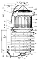
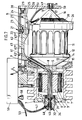
- the delivery device has a housing 1 to be fastened, for example, to a carrier of a weaving machine.
- This houses a stator 3 in a housing cavity 2, in which a rotor 4 rotates.
- the latter is penetrated by a rotor shaft 5.
- Its thread-threading end sits in a roller bearing 6, which is inserted in a cover 7 closing the housing cavity 2.
- a cross-sectionally larger collar 8 of the rotor shaft 5 facing away from the threading end starts from an inclined thread guide tube 9, the mouth end 10 of which is bent in the axial direction of a storage drum 11 arranged coaxially to the rotor shaft 5.
- the storage drum 11 forms a thread run-up truncated cone surface 12, so that when the thread guide tube 9 rotates, the rear thread turns advance the front thread turns already on the storage drum toward the head end of the storage drum 11.
- the storage drum itself is rotatably arranged. So that it does not rotate together with the thread guide tube 9, it is firmly connected to a truncated cone 13 equipped with magnets, not shown. Its magnets are located opposite to fixed magnets 14 of a ring 15 on the housing side.
- the storage drum 11 At its free-flying front end, the storage drum 11 carries a head cone 16. Its base lies against the front side of the storage drum and is somewhat smaller than the diameter of the storage drum 11.
- the lateral surface area M of the head cone 16 starts from the base edge B and extends in a straight line up to to the cone tip 17. The same extends to the inlet opening 18 of a thread take-off eye 19.
- the extension arm 21 which extends beyond the storage drum 11 is located at such a parallel distance from the storage drum 11 that it does not impair the orbital movement of the thread guide tube 9.
- the boom 21 receives a compressed air cylinder 22. Its piston rod 23 engages a sliding carriage 24 which is longitudinally displaceable in the interior of the boom 21. Relative to this, a carrier 25 is guided for a brake ring 26 that runs concentrically to the storage drum axis.
- the sliding carriage 24 supports an adjusting screw 27, for the actuating end 28 of which the baffle 20 forms an opening 29. Rotating the actuating handle 28 is accompanied by a longitudinal displacement of the carrier 25, depending on the direction in which the brake ring 26 is to be adjusted.
- the brake ring 26 is provided with bristles 30 directed toward the drum in such a way that they are aligned with the lateral surface of the head cone 16. In the working position, the bristle ends rest against the head cone 16 of the storage drum 11.
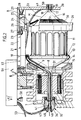
- the thread guide tube 9 continues into a thread channel 31 which extends centrally through the rotor shaft and which widens at the end on the threading side.
- a suction blow nozzle 32 is provided in the housing cover 7.
- a spacer sleeve 33 In a central opening of the housing cover 7 there is a spacer sleeve 33 in which the nozzle housing 34 is firmly inserted.
- the nozzle housing 34 receives at its end facing the rotor shaft 5 a sealing collar 35 which extends to the free end of the rotor shaft 5. Accordingly, the thread channel 31 directly adjoins the outlet opening 36 of the sealing collar 35.
- the outlet opening 36 in turn is connected to a short through-flow channel 37 of the nozzle body 34, which channel 37 subsequently widens into a frustoconical channel 38 in order to then merge into a circular-cylindrical channel section 39.
- a nozzle body 40 is pressed into this. In the middle, it forms a thread passage channel 41, which is smaller in diameter than that of the flow channel 37 in the nozzle body 34.
- the nozzle body 40 is equipped with a truncated cone section 42, the cone angle of which is smaller than that of the truncated cone Channel 38.
- the smallest diameter of the truncated cone section 42 is smaller than that of the flow channel 37, so that an annular gap 43 remains accordingly.
- the nozzle body 40 On its circular-cylindrical remaining length, the nozzle body 40 forms an annular chamber 44, in whose wall 45 on the annular gap side a ring of air passage holes 46 is provided. A compressed air supply line 47 opens into the annular chamber 44. A threading eyelet 48 is then arranged upstream of the nozzle body 40 and is in turn firmly embedded in the nozzle housing 44.
- the thread take-off eye 19 is also designed as a suction blowing nozzle. It has a nozzle housing 49 inserted into the baffle wall 20 with a nozzle body 50 which corresponds in structure to that of the suction blowing nozzle 32.
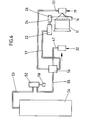
- a common valve 52 is assigned to the feed lines 47, 51 of the two suction blowing nozzles 19, 32. The latter is connected to a compressed air source 54 via a compressed air line 53.
- a feed line 55 extends from the valve 52 to a distributor 56, which is connected both to the supply lines 47, 51 and to the supply line 57, which leads to the compressed air cylinder 22 .
- the valve 52 can be controlled by means of a handle 58.
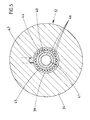
- both the suction blowing nozzles 19, 32 and the compressed air cylinder 22 are fed via the compressed air line 53 and feed line 55 via the distributor 56, which displaces the brake ring 26 in the axial direction in such a way that its bristles enter a gap position with respect to the drum surface, see gap 60 in Fig. 3.
- the aforementioned handle 58 is advantageously located on a box 59 connected to the housing 1, in which the valve 52 as well as the distributor 56 and the corresponding connections are accommodated.
- the width of the baffle 20 receiving the suction blowing nozzle 19 corresponds approximately to one third of the diameter of the storage drum 11.
- the rotor shaft 5 Before threading a thread F, the rotor shaft 5 is stopped in such a position that the thread guide tube 9 originating from the collar 8 or its mouth end 10 lies in a plane vertically above the thread take-off eye 19.
- the handle 58 is then to be actuated, the suction blowing nozzles 19, 32 receiving compressed air at the same time.
- This also applies to the compressed air cylinder 22, which displaces the brake ring 26 via its piston rod 23 and sliding carriage 24, so that its bristles reach a gap-forming release position, cf. Fig. 3.
- the thread end is now to be brought into the area of the threading eyelet 48.
- the radially inward on the thread take-off Eyelet 19 directed deflection then takes place by means of the suction air flow lying on the lateral surface of the head cone 16, which deflection is supported by the gravity of the thread end.
- the baffle 20 represents a limitation of the trajectory, so that the thread end does not go beyond the baffle, but surely reaches the extraction eyelet 19 designed as a suction blow nozzle and from there also emerges from the venturi principle.
- the handle 58 can return to its starting position with the interruption of the compressed air supply.
- a spring, not shown, housed in the compressed air cylinder 22 then returns the brake ring 26 to its starting position.
- the bent mouth end 10 is missing in the thread guide tube 9.
- the mouth end 61 which in this second exemplary embodiment extends in the same direction as the thread guide tube, is directed into a deflection channel 62 running parallel to the storage drum axis direction. This is located in a block 63 inserted into the boom 21 and extending below the compressed air cylinder 22.
- the deflection channel 62 has three adjoining bottom sections 62 ', 62 ", 62"'.
- the third bottom section 62'" runs at an opposite angle to the drum axis and directs the thread end into the gap 60 between bristles 30 and storage drum in the direction of the head cone 16, baffle 20 and suction blow nozzle 19.
- the threading process is also carried out while the handle 58 is pressed.
- the deflection of the thread now takes place in the transition region between the mouth end 61 and the suction blowing nozzle 19 through the deflection channel 62, so that additional deflection nozzles can also be omitted in this version.
- the funnel-shaped enlargement 64 of the deflection channel 62 on the input side has a facilitating effect during the threading process.
- the threading of the thread always takes place in the position in which the mouth end 51 of the thread guide tube 9 is located in a plane vertically above the thread take-off eye. Then both the force of gravity and the corresponding lateral surface of the head cone located in the same plane can be used for thread guidance.
Landscapes
- Engineering & Computer Science (AREA)
- Textile Engineering (AREA)
- Forwarding And Storing Of Filamentary Material (AREA)
- Looms (AREA)
- Yarns And Mechanical Finishing Of Yarns Or Ropes (AREA)
- Coiling Of Filamentary Materials In General (AREA)
- Spinning Methods And Devices For Manufacturing Artificial Fibers (AREA)
- Spinning Or Twisting Of Yarns (AREA)
- Application Of Or Painting With Fluid Materials (AREA)
- Extrusion Moulding Of Plastics Or The Like (AREA)
- Braiding, Manufacturing Of Bobbin-Net Or Lace, And Manufacturing Of Nets By Knotting (AREA)
- Treatment Of Fiber Materials (AREA)
Claims (15)
Priority Applications (3)
| Application Number | Priority Date | Filing Date | Title |
|---|---|---|---|
| EP94119612A EP0657379A2 (fr) | 1990-03-07 | 1990-12-10 | Dispositif fournisseur de fil |
| EP94116058A EP0659918B1 (fr) | 1990-03-07 | 1990-12-10 | Dispositif fournisseur de fil |
| DE9018101U DE9018101U1 (de) | 1990-03-07 | 1990-12-10 | Liefervorrichtung für laufende Fäden |
Applications Claiming Priority (2)
| Application Number | Priority Date | Filing Date | Title |
|---|---|---|---|
| DE4007131 | 1990-03-07 | ||
| DE4007131A DE4007131C2 (de) | 1990-03-07 | 1990-03-07 | Liefervorrichtung für laufende Fäden |
Related Child Applications (3)
| Application Number | Title | Priority Date | Filing Date |
|---|---|---|---|
| EP94116058A Division EP0659918B1 (fr) | 1990-03-07 | 1990-12-10 | Dispositif fournisseur de fil |
| EP94116058.2 Division-Into | 1994-10-12 | ||
| EP94119612.3 Division-Into | 1994-12-12 |
Publications (3)
| Publication Number | Publication Date |
|---|---|
| EP0446447A1 EP0446447A1 (fr) | 1991-09-18 |
| EP0446447B1 true EP0446447B1 (fr) | 1995-07-05 |
| EP0446447B2 EP0446447B2 (fr) | 2000-11-22 |
Family
ID=6401592
Family Applications (3)
| Application Number | Title | Priority Date | Filing Date |
|---|---|---|---|
| EP94116058A Expired - Lifetime EP0659918B1 (fr) | 1990-03-07 | 1990-12-10 | Dispositif fournisseur de fil |
| EP90123730A Expired - Lifetime EP0446447B2 (fr) | 1990-03-07 | 1990-12-10 | Dispositif fournisseur de fil |
| EP94119612A Withdrawn EP0657379A2 (fr) | 1990-03-07 | 1990-12-10 | Dispositif fournisseur de fil |
Family Applications Before (1)
| Application Number | Title | Priority Date | Filing Date |
|---|---|---|---|
| EP94116058A Expired - Lifetime EP0659918B1 (fr) | 1990-03-07 | 1990-12-10 | Dispositif fournisseur de fil |
Family Applications After (1)
| Application Number | Title | Priority Date | Filing Date |
|---|---|---|---|
| EP94119612A Withdrawn EP0657379A2 (fr) | 1990-03-07 | 1990-12-10 | Dispositif fournisseur de fil |
Country Status (9)
| Country | Link |
|---|---|
| US (1) | US5181544A (fr) |
| EP (3) | EP0659918B1 (fr) |
| JP (1) | JP3021712B2 (fr) |
| CN (1) | CN1026424C (fr) |
| AT (2) | ATE253134T1 (fr) |
| BR (1) | BR9100911A (fr) |
| CZ (1) | CZ281399B6 (fr) |
| DE (3) | DE4007131C2 (fr) |
| ES (1) | ES2074112T3 (fr) |
Families Citing this family (28)
| Publication number | Priority date | Publication date | Assignee | Title |
|---|---|---|---|---|
| DE9117045U1 (de) * | 1991-06-18 | 1995-05-11 | Iro Ab, Ulricehamn | Fadenspeicher- und -liefervorrichtung |
| IT226136Y1 (it) * | 1991-09-19 | 1997-04-18 | Roy Electrotex Spa | Miglioramenti costruttivi per porgitrama per telai di tessitura. |
| IT1259551B (it) * | 1992-04-22 | 1996-03-20 | Lgl Electronics Spa | Dispositivo elettropneumatico per l'infilaggio automatico di apparecchi alimentatori di trama a macchine tessili ed apparecchio alimentatore di trama incorporante detto dispositivo |
| IT1258241B (it) * | 1992-11-05 | 1996-02-22 | Alimentatore di trama | |
| IT1263623B (it) * | 1993-02-23 | 1996-08-27 | Roj Electrotex Nuova Srl | Alimentatore di filo |
| SE508469C2 (sv) * | 1993-04-21 | 1998-10-12 | Sipra Patent Beteiligung | Garnmataranordning i en textilmaskin samt förfarande för användning av garnmataranordning |
| DE9307967U1 (de) * | 1993-05-26 | 1994-10-06 | Palitex Project-Company GmbH, 47804 Krefeld | Doppeldraht-Zwirnspindel |
| TW286331B (fr) * | 1994-03-03 | 1996-09-21 | Micron Instr | |
| DE9406102U1 (de) * | 1994-04-13 | 1995-08-10 | Sobrevin Société de brevets industriels-Etablissement, Vaduz | Fadenspeicher mit Fadenabzugsbremse |
| US5546994A (en) * | 1994-10-14 | 1996-08-20 | Sobrevin Societe De Brevets Industriels-Etablissement | Thread storage drum with frustoconical brake strip |
| IT1280434B1 (it) * | 1995-07-18 | 1998-01-20 | Lgl Electronics Spa | Dispositivo elettropneumatico perfezionato per l'infilaggio automatico di apparecchi alimentatori di trama ed alimentatore di |
| DE19533310A1 (de) * | 1995-07-24 | 1997-01-30 | Iro Ab | Fadenliefergerät |
| US5947403A (en) * | 1995-07-24 | 1999-09-07 | Iro Ab | Yarn feeding device |
| DE19533547A1 (de) * | 1995-09-11 | 1997-03-13 | Iro Ab | Pneumatische Ventileinrichtung für ein Fadenliefergerät und Fadenliefergerät |
| DE19609871A1 (de) * | 1996-03-13 | 1997-09-18 | Iro Ab | Fadenliefergerät |
| IT239803Y1 (it) * | 1996-09-03 | 2001-03-13 | Lgl Electronics Spa | Dispositivo di ritegno a sgancio rapido del supporto portafreno diapparecchi alimentatori di trama per macchine tessili |
| IT1302068B1 (it) * | 1998-02-26 | 2000-07-20 | Lgl Electronics Spa | Metodo e dispositivo di infilaggio pneumatico di apparecchialimentatori di trama a macchine tessili. |
| DE10107688A1 (de) * | 2001-02-19 | 2002-08-29 | Iro Patent Ag Baar | Fadenliefergerät |
| ITTO20020023U1 (it) * | 2002-02-01 | 2003-08-01 | Lgl Electronics Spa | ,,dispositivo di ritegno del supporto portafreno in dispositivi alimentatori di trama,, |
| DE10358283A1 (de) * | 2003-12-12 | 2005-07-21 | Iro Ab | Fadenmessliefergerät |
| SE0400861D0 (sv) * | 2004-04-01 | 2004-04-01 | Iropa Ag | Garnmatningsanordning |
| CN102634913A (zh) * | 2012-04-06 | 2012-08-15 | 经纬纺织机械股份有限公司 | 无捻度变化储纬装置 |
| IT201800007866A1 (it) * | 2018-08-06 | 2020-02-06 | Lgl Electronics Spa | Dispositivo frena-trama per alimentatori di filato ad accumulo |
| CZ2019389A3 (cs) * | 2019-06-19 | 2020-12-30 | Rieter Cz S.R.O. | Zařízení pro nasávání a dopravu příze pro uspořádání na obslužném robotu textilního stroje pro výrobu příze, obslužný robot pro obsluhu pracovního místa textilního stroje a textilní stroj |
| CN112553764A (zh) * | 2020-12-01 | 2021-03-26 | 张家港市凯利雅特种纺织纱线有限公司 | 氨纶纱输纱装置 |
| CN112609299B (zh) * | 2020-12-10 | 2022-08-19 | 青岛村田机械制造有限公司 | 一种在操作时避免储纬器处断纬或漏纬的纺织储纬装置 |
| CN114000246B (zh) * | 2021-11-30 | 2022-11-29 | 嵊州市三凌动力科技有限公司 | 储纬器用三角压片及其制造方法 |
| CN119160714B (zh) * | 2024-11-22 | 2025-03-18 | 山东明福染业有限公司 | 一种用于植物染色的纱线收集装置 |
Family Cites Families (7)
| Publication number | Priority date | Publication date | Assignee | Title |
|---|---|---|---|---|
| BE759801A (fr) * | 1969-12-04 | 1971-05-17 | Snia Viscosa | Perfectionnements apportes aux dispositifs pour ramasser, aspirer et eliminer des filaments et fils textiles, ainsi que les dispositifs perfectionnes obtenus |
| IT1133900B (it) * | 1980-10-15 | 1986-07-24 | Roy Electrotex Spa | Mezzi per effettuare la frenatura del filato in uscita in dispositivi alimentatori di filato a tensione costante e regolabile,particolarmente per macchine tessili |
| DE8712946U1 (de) * | 1987-09-25 | 1987-12-10 | Aktiebolaget Iro, Ulricehamn | Fadenspeicher- und -liefervorrichtung |
| US4969489A (en) * | 1988-07-14 | 1990-11-13 | Nissan Motor Co., Ltd. | Weft threading system for fluid jet loom using the storage drum winding arm |
| US5016680A (en) * | 1989-03-03 | 1991-05-21 | Kabushiki Kaisha Toyoda Jidoshokki Seisakusho | Weft processing and releasing apparatus in a jet loom |
| IT1236993B (it) * | 1989-12-29 | 1993-05-12 | Roy Electrotex Spa | Alimentatore di trama per telai di tessitura a pinze e a proiettili |
| FR2978758B1 (fr) | 2011-08-02 | 2013-08-02 | Saint Gobain | Enceinte de flottage du verre |
-
1990
- 1990-03-07 DE DE4007131A patent/DE4007131C2/de not_active Expired - Fee Related
- 1990-12-10 AT AT94116058T patent/ATE253134T1/de not_active IP Right Cessation
- 1990-12-10 AT AT90123730T patent/ATE124732T1/de not_active IP Right Cessation
- 1990-12-10 ES ES90123730T patent/ES2074112T3/es not_active Expired - Lifetime
- 1990-12-10 EP EP94116058A patent/EP0659918B1/fr not_active Expired - Lifetime
- 1990-12-10 DE DE59009377T patent/DE59009377D1/de not_active Expired - Lifetime
- 1990-12-10 EP EP90123730A patent/EP0446447B2/fr not_active Expired - Lifetime
- 1990-12-10 DE DE59010936T patent/DE59010936D1/de not_active Expired - Fee Related
- 1990-12-10 EP EP94119612A patent/EP0657379A2/fr not_active Withdrawn
-
1991
- 1991-01-29 US US07/647,052 patent/US5181544A/en not_active Expired - Lifetime
- 1991-02-20 CN CN91101057A patent/CN1026424C/zh not_active Expired - Fee Related
- 1991-03-06 BR BR919100911A patent/BR9100911A/pt unknown
- 1991-03-06 CZ CS91584A patent/CZ281399B6/cs unknown
- 1991-03-07 JP JP3041947A patent/JP3021712B2/ja not_active Expired - Fee Related
Also Published As
| Publication number | Publication date |
|---|---|
| CN1026424C (zh) | 1994-11-02 |
| DE59009377D1 (de) | 1995-08-10 |
| DE4007131A1 (de) | 1991-09-12 |
| ATE253134T1 (de) | 2003-11-15 |
| DE4007131C2 (de) | 1999-12-30 |
| JP3021712B2 (ja) | 2000-03-15 |
| US5181544A (en) | 1993-01-26 |
| EP0659918A2 (fr) | 1995-06-28 |
| BR9100911A (pt) | 1991-11-05 |
| ES2074112T3 (es) | 1995-09-01 |
| CN1054624A (zh) | 1991-09-18 |
| CZ281399B6 (cs) | 1996-09-11 |
| ATE124732T1 (de) | 1995-07-15 |
| EP0446447A1 (fr) | 1991-09-18 |
| CS9100584A2 (en) | 1991-09-15 |
| EP0659918B1 (fr) | 2003-10-29 |
| DE59010936D1 (de) | 2003-12-04 |
| EP0659918A3 (fr) | 1997-11-19 |
| JPH04213561A (ja) | 1992-08-04 |
| EP0446447B2 (fr) | 2000-11-22 |
| EP0657379A2 (fr) | 1995-06-14 |
Similar Documents
| Publication | Publication Date | Title |
|---|---|---|
| EP0446447B1 (fr) | Dispositif fournisseur de fil | |
| WO2008095631A1 (fr) | Dispositif de filage à air | |
| CH681894A5 (fr) | ||
| DE102016119983A1 (de) | Pneumatisches Fadenspeicherorgan, Arbeitsstelle einer Textilmaschine mit einem Fadenspeicherorgan und Textilmaschine mit einer Vielzahl von Arbeitsstellen mit einem Fadenspeicherorgan | |
| CH682913A5 (de) | Verfahren und Vorrichtung zum Vorbereiten zu spleissender Fadenenden. | |
| DE3444821A1 (de) | Vorrichtung zum einlegen des fadenendes einer textilspule in die spulenhuelse | |
| EP0365472B1 (fr) | Dispositif pour enfiler un fil dans un métier à tisser | |
| DE2758064B2 (de) | Verfahren und Vorrichtung zum Beseitigen einer Unregelmäßigkeit im Faden an einer Spinnstelle einer Offen-End-Spinnvorrichtung | |
| DE3025068A1 (de) | Vorrichtung fuer die zufuehrung von textilem bandmaterial an einen verbraucher | |
| DE3819426C2 (fr) | ||
| EP0527355A1 (fr) | Procédé et dispositif pour l'introduction pneumatique d'une mèche de fibres dans un métier à filer | |
| CH673024A5 (fr) | ||
| DE3734284A1 (de) | Fadenspeicher- und -liefervorrichtung | |
| EP0822276B1 (fr) | Dispositif pour contrôler le courant d'air dans un métier à filer à bout ouvert | |
| DE4000856A1 (de) | Schussseitig angeordnete fadenschneidevorrichtung einer luftwebmaschine | |
| CH652994A5 (de) | Verfahren und spulmaschine zum aufwickeln eines mit hoher geschwindigkeit kontinuierlich angelieferten fadens auf eine spule. | |
| DE9018101U1 (de) | Liefervorrichtung für laufende Fäden | |
| DE10150565B4 (de) | Verfahren und Vorrichtung zur Vorbereitung eines abgelängten Fadenendes für das Wiederanspinnen einer Offenend-Spinnvorrichtung | |
| DE1535570B1 (de) | Saugkanal zur Bildung einer Schleife eines Schussfadens an Webmaschinen mit Entnahme des Schussfadens von ortsfesten Spulen | |
| DE3247288C2 (de) | Verfahren zur Aufbereitung eines Garnendes für das Anspinnen in einem Spinnrotor einer Offenendspinneinheit und Vorrichtung zur Durchführung des Verfahrens | |
| DE3915608A1 (de) | Aufspulmaschine | |
| DE1069044B (de) | Anzwirnvorrichtung für eine Streckzwirnmaschine | |
| EP0294795B1 (fr) | Procédé et dispositif pour rattacher un fil sur une machine de filature à friction | |
| DE102006018242A1 (de) | Luftdüsenspinnvorrichtung | |
| DE1535570C (de) | Saugkanal zur Bildung einer Schleife eines Schußfadens an Webmaschinen mit Entnahme des Schußfadens von ortsfesten Spulen |
Legal Events
| Date | Code | Title | Description |
|---|---|---|---|
| PUAI | Public reference made under article 153(3) epc to a published international application that has entered the european phase |
Free format text: ORIGINAL CODE: 0009012 |
|
| AK | Designated contracting states |
Kind code of ref document: A1 Designated state(s): AT BE CH DE DK ES FR GB GR IT LI LU NL SE |
|
| 17P | Request for examination filed |
Effective date: 19910912 |
|
| 17Q | First examination report despatched |
Effective date: 19930824 |
|
| GRAA | (expected) grant |
Free format text: ORIGINAL CODE: 0009210 |
|
| AK | Designated contracting states |
Kind code of ref document: B1 Designated state(s): AT BE CH DE DK ES FR GB GR IT LI LU NL SE |
|
| PG25 | Lapsed in a contracting state [announced via postgrant information from national office to epo] |
Ref country code: DK Effective date: 19950705 Ref country code: GR Free format text: LAPSE BECAUSE OF FAILURE TO SUBMIT A TRANSLATION OF THE DESCRIPTION OR TO PAY THE FEE WITHIN THE PRESCRIBED TIME-LIMIT Effective date: 19950705 |
|
| REF | Corresponds to: |
Ref document number: 124732 Country of ref document: AT Date of ref document: 19950715 Kind code of ref document: T |
|
| XX | Miscellaneous (additional remarks) |
Free format text: TEILANMELDUNG 94116058.2 EINGEREICHT AM 10/12/90. |
|
| ET | Fr: translation filed | ||
| REF | Corresponds to: |
Ref document number: 59009377 Country of ref document: DE Date of ref document: 19950810 |
|
| GBT | Gb: translation of ep patent filed (gb section 77(6)(a)/1977) |
Effective date: 19950720 |
|
| REG | Reference to a national code |
Ref country code: ES Ref legal event code: FG2A Ref document number: 2074112 Country of ref document: ES Kind code of ref document: T3 |
|
| ITF | It: translation for a ep patent filed | ||
| PGFP | Annual fee paid to national office [announced via postgrant information from national office to epo] |
Ref country code: LU Payment date: 19951101 Year of fee payment: 6 |
|
| PGFP | Annual fee paid to national office [announced via postgrant information from national office to epo] |
Ref country code: AT Payment date: 19951213 Year of fee payment: 6 |
|
| PGFP | Annual fee paid to national office [announced via postgrant information from national office to epo] |
Ref country code: NL Payment date: 19951230 Year of fee payment: 6 |
|
| PLBI | Opposition filed |
Free format text: ORIGINAL CODE: 0009260 |
|
| PLBQ | Unpublished change to opponent data |
Free format text: ORIGINAL CODE: EPIDOS OPPO |
|
| 26 | Opposition filed |
Opponent name: IRO AB Effective date: 19951208 |
|
| NLR1 | Nl: opposition has been filed with the epo |
Opponent name: IRO AB |
|
| PLBF | Reply of patent proprietor to notice(s) of opposition |
Free format text: ORIGINAL CODE: EPIDOS OBSO |
|
| PLBF | Reply of patent proprietor to notice(s) of opposition |
Free format text: ORIGINAL CODE: EPIDOS OBSO |
|
| RDAH | Patent revoked |
Free format text: ORIGINAL CODE: EPIDOS REVO |
|
| PG25 | Lapsed in a contracting state [announced via postgrant information from national office to epo] |
Ref country code: LU Free format text: LAPSE BECAUSE OF NON-PAYMENT OF DUE FEES Effective date: 19961210 Ref country code: AT Effective date: 19961210 |
|
| APAC | Appeal dossier modified |
Free format text: ORIGINAL CODE: EPIDOS NOAPO |
|
| APAE | Appeal reference modified |
Free format text: ORIGINAL CODE: EPIDOS REFNO |
|
| PG25 | Lapsed in a contracting state [announced via postgrant information from national office to epo] |
Ref country code: NL Effective date: 19970701 |
|
| NLV4 | Nl: lapsed or anulled due to non-payment of the annual fee |
Effective date: 19970701 |
|
| PGFP | Annual fee paid to national office [announced via postgrant information from national office to epo] |
Ref country code: GB Payment date: 19971015 Year of fee payment: 8 |
|
| PGFP | Annual fee paid to national office [announced via postgrant information from national office to epo] |
Ref country code: SE Payment date: 19971218 Year of fee payment: 8 |
|
| PGFP | Annual fee paid to national office [announced via postgrant information from national office to epo] |
Ref country code: ES Payment date: 19971230 Year of fee payment: 8 |
|
| PG25 | Lapsed in a contracting state [announced via postgrant information from national office to epo] |
Ref country code: GB Free format text: LAPSE BECAUSE OF NON-PAYMENT OF DUE FEES Effective date: 19981210 |
|
| PG25 | Lapsed in a contracting state [announced via postgrant information from national office to epo] |
Ref country code: SE Free format text: LAPSE BECAUSE OF NON-PAYMENT OF DUE FEES Effective date: 19981211 |
|
| GBPC | Gb: european patent ceased through non-payment of renewal fee |
Effective date: 19981210 |
|
| APAE | Appeal reference modified |
Free format text: ORIGINAL CODE: EPIDOS REFNO |
|
| APAC | Appeal dossier modified |
Free format text: ORIGINAL CODE: EPIDOS NOAPO |
|
| PLAW | Interlocutory decision in opposition |
Free format text: ORIGINAL CODE: EPIDOS IDOP |
|
| PLAW | Interlocutory decision in opposition |
Free format text: ORIGINAL CODE: EPIDOS IDOP |
|
| PUAH | Patent maintained in amended form |
Free format text: ORIGINAL CODE: 0009272 |
|
| STAA | Information on the status of an ep patent application or granted ep patent |
Free format text: STATUS: PATENT MAINTAINED AS AMENDED |
|
| 27A | Patent maintained in amended form |
Effective date: 20001122 |
|
| AK | Designated contracting states |
Kind code of ref document: B2 Designated state(s): AT BE CH DE DK ES FR GB GR IT LI LU NL SE |
|
| XX | Miscellaneous (additional remarks) |
Free format text: TEILANMELDUNG 94116058.2 EINGEREICHT AM 10/12/90. |
|
| ET3 | Fr: translation filed ** decision concerning opposition | ||
| REG | Reference to a national code |
Ref country code: CH Ref legal event code: AEN Free format text: AUFRECHTERHALTUNG DES PATENTES IN GEAENDERTER FORM |
|
| ITF | It: translation for a ep patent filed | ||
| PG25 | Lapsed in a contracting state [announced via postgrant information from national office to epo] |
Ref country code: ES Free format text: LAPSE BECAUSE OF FAILURE TO SUBMIT A TRANSLATION OF THE DESCRIPTION OR TO PAY THE FEE WITHIN THE PRESCRIBED TIME-LIMIT Effective date: 20010304 |
|
| PGFP | Annual fee paid to national office [announced via postgrant information from national office to epo] |
Ref country code: FR Payment date: 20011220 Year of fee payment: 12 |
|
| PGFP | Annual fee paid to national office [announced via postgrant information from national office to epo] |
Ref country code: CH Payment date: 20020110 Year of fee payment: 12 |
|
| PG25 | Lapsed in a contracting state [announced via postgrant information from national office to epo] |
Ref country code: LI Free format text: LAPSE BECAUSE OF NON-PAYMENT OF DUE FEES Effective date: 20021231 Ref country code: CH Free format text: LAPSE BECAUSE OF NON-PAYMENT OF DUE FEES Effective date: 20021231 |
|
| REG | Reference to a national code |
Ref country code: CH Ref legal event code: PL |
|
| PG25 | Lapsed in a contracting state [announced via postgrant information from national office to epo] |
Ref country code: FR Free format text: LAPSE BECAUSE OF NON-PAYMENT OF DUE FEES Effective date: 20030901 |
|
| REG | Reference to a national code |
Ref country code: FR Ref legal event code: ST |
|
| APAH | Appeal reference modified |
Free format text: ORIGINAL CODE: EPIDOSCREFNO |
|
| PGFP | Annual fee paid to national office [announced via postgrant information from national office to epo] |
Ref country code: BE Payment date: 20061205 Year of fee payment: 17 |
|
| PGFP | Annual fee paid to national office [announced via postgrant information from national office to epo] |
Ref country code: IT Payment date: 20071220 Year of fee payment: 18 |
|
| BERE | Be: lapsed |
Owner name: SOC. DE BREVETS INDUSTRIELS-ETABLISSEMENT *SOBREVI Effective date: 20071231 |
|
| PG25 | Lapsed in a contracting state [announced via postgrant information from national office to epo] |
Ref country code: BE Free format text: LAPSE BECAUSE OF NON-PAYMENT OF DUE FEES Effective date: 20071231 |
|
| PG25 | Lapsed in a contracting state [announced via postgrant information from national office to epo] |
Ref country code: ES Free format text: LAPSE BECAUSE OF FAILURE TO SUBMIT A TRANSLATION OF THE DESCRIPTION OR TO PAY THE FEE WITHIN THE PRESCRIBED TIME-LIMIT Effective date: 19981231 |
|
| PGFP | Annual fee paid to national office [announced via postgrant information from national office to epo] |
Ref country code: DE Payment date: 20100222 Year of fee payment: 20 |
|
| PG25 | Lapsed in a contracting state [announced via postgrant information from national office to epo] |
Ref country code: DE Free format text: LAPSE BECAUSE OF EXPIRATION OF PROTECTION Effective date: 20101210 |
|
| PG25 | Lapsed in a contracting state [announced via postgrant information from national office to epo] |
Ref country code: IT Free format text: LAPSE BECAUSE OF NON-PAYMENT OF DUE FEES Effective date: 20081210 |