EP0446881B1 - Sound effect device for radio controllable toy vehicle - Google Patents
Sound effect device for radio controllable toy vehicle Download PDFInfo
- Publication number
- EP0446881B1 EP0446881B1 EP91103792A EP91103792A EP0446881B1 EP 0446881 B1 EP0446881 B1 EP 0446881B1 EP 91103792 A EP91103792 A EP 91103792A EP 91103792 A EP91103792 A EP 91103792A EP 0446881 B1 EP0446881 B1 EP 0446881B1
- Authority
- EP
- European Patent Office
- Prior art keywords
- sound
- switch
- microcomputer
- engine
- toy vehicle
- Prior art date
- Legal status (The legal status is an assumption and is not a legal conclusion. Google has not performed a legal analysis and makes no representation as to the accuracy of the status listed.)
- Expired - Lifetime
Links
Images


Classifications
-
- A—HUMAN NECESSITIES
- A63—SPORTS; GAMES; AMUSEMENTS
- A63H—TOYS, e.g. TOPS, DOLLS, HOOPS OR BUILDING BLOCKS
- A63H17/00—Toy vehicles, e.g. with self-drive; ; Cranes, winches or the like; Accessories therefor
- A63H17/26—Details; Accessories
- A63H17/34—Arrangements for imitating the noise of motors
Definitions
- This invention relates to a radio-controllable toy vehicle having a built-in sound effect device in accordance with the preamble of claim 1.
- a toy vehicle is disclosed in Japanese Utility Model publication No. 60-39040.
- the sound effect device disclosed in this document is capable of producing a pseudo idling sound which is generated in a normal driving condition, and a realistic engine sound proportionate to the number of revolutions of a power drive unit such as a drive shaft or wheel, on the basis of a pulse signal corresponding to the number of revolutions of the power drive unit.
- a pulse signal is generated due to a change in the number of revolutions of the drive unit, no realistic engine sounds such as an engine racing sound and various engine sounds generated upon gear-shifting can be produced when the number of revolutions is zero or not changed.
- An improved toy vehicle comprising a sound effect device according to the preamble of claim 1 developed in order to eliminate aforementioned problem is disclosed in Japanese Patent Laid-Open publication No. 62-277983.
- the device differs from the foregoing conventional one in employing a one-shot pulse generator provided on a transmitter and a controller provided on a receiver for generating a realistic engine sound.
- the generator emits a neutral pulse signal so as to switch a driving condition of a toy vehicle between idling and running by shifting a change-over switch of the transmitter between ON- and OFF-positions, respectively.
- the controller controls the engine sound generation on the basis of the neutral pulse signal and a direct-current voltage signal proportionate to a number of revolutions of a motor depending upon a drive pulse signal.
- the controller includes a voltage variable frequency circuit, wherein, when a driving condition of the toy vehicle is switched from idling to running and vice versa, a direct current voltage is varied by integrating means so that a wave form of the varied voltage has saw-tooth shape. Depending upon the saw-tooth shape of the varied voltage and the neutral pulse signal, the controller generates realistic engine sounds such as an engine racing sound upon idling and engine acceleration and deceleration sounds upon gear-shifting.
- the conventional improved toy vehicle producing the aforementioned realistic engine sounds consistent with a driving condition of the toy vehicle can not generate a wide variety of realistic sounds such as a rotation sound of a starting motor, an engine acceleration sound, an idling sound, a tire-squealing sound upon sharp turning and a braking sound.
- the conventional improved toy vehicle in order to generate a special kind of sound such as a turbo engine sound, is provided with an oscillator having a fixed frequency which emits a pulse corresponding to the sound.
- the conventional improved toy vehicle since the time constant of an integrating circuit should be changed in order to produce separate types of realistic sounds upon engine-racing or gear-shifting, the conventional improved toy vehicle is also provided with a switch circuit for increasing or decreasing capacity which is necessary upon changing the time constant according to the driving condition of the toy vehicle. To this end, the conventional improved toy vehicle has a complicated circuit constitution.
- an engine sound on/off switch and a starting motor sound on/off switch are provided in the inventive toy vehicle, which switches are electrically connected to the microcomputer.
- the microcomputer receives signals relative to a driving condition of the toy vehicle which are delivered from the decoder circuit.
- the microcomputer is set to perform a processing for generating realistic engine sounds through the amplifier in the speaker depending upon the delivered signals, and subsequently a rotation sound of the starting motor, an engine acceleration sound and an idling sound.
- FIG. 1 is a circuit diagram of a sound effect device of a toy vehicle according to the present invention
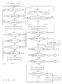
- FIGS. 2 to 5 are flow charts illustrating each of steps in the sound effect processing for producing various realistic sounds, which is conducted by a 1-chip microcomputer shown in FIG. 1.
- a circuit diagram of a sound effect device used for a radio controllable toy vehicle shows a transmitter 10, a receiving circuit 12 for receiving a signal from the transmitter 10, a decoder circuit 14 for generating a radio control signal, a power-motor drive circuit 16, a steering drive circuit 18, a motor unit 20, a steering unit 22, a 1-chip microcomputer 24, an amplifier 26, a speaker 28, an engine sound on/off switch 30 and a starting motor sound on/off switch 32 for energizing a starting motor.
- the receiving circuit 12 built in a radio-controllable toy vehicle serves for receiving a signal delivered from the transmitter 10.
- the radio control signal received is to the decoder circuit 14 and converted therein into separate signals for controlling the motor unit (MU) 20 and the steering unit (SU) 22.
- the signals converted are respectively transmitted to the power-motor drive circuit 16 and the steering drive circuit 18, so that the motor unit 20 and the steering unit 22 are actuated. Accordingly, the toy vehicle is controllably maneuvered or travelled in forward and backward direction and allowed to turn right and left by actuation of control sticks (not shown in the drawings) provided onto the transmitter 10.
- the decoder circuit 14 includes a plurality of output terminals, for instance a right-turn signal output terminal (1), a left-turn signal output terminal (2), a reverse motion signal output terminal (3), a forward motion signal output terminal (4), a turbo signal output terminal (5) and a klaxon horn signal output terminal (6), which are respectively connected to the microcomputer 24.
- the engine sound on/off switch 30 and the startingmotor sound on/off switch 32 are connected to the microcomputer 24.
- a speaker 28 is connected through an amplifier 26 to the microcomputer 24.
- a sound effect processing is started by a program stored in ROM (not shown in the drawings) of the microcomputer 24 on the basis of the signal delivered from the output terminal. Namely, many kinds of sounds which simulate various driving conditions are realistically emitted in the speaker 28 of the toy vehicle.
- FIGS. 2 to 5 are flow chart illustrating steps in the sound effect processing conducted by the microcomputer 24 according to a driving condition of the toy vehicle such as a racing car.
- the sound effect processing is controlled by the microcomputer 24 as follows.
- a main switch for power supply (not shown in the drawings) disposed on the toy vehicle is turned on.
- the microcomputer 24 starts in SILENT mode in which no sound is generated.
- the engine sound on/off switch 30 is shifted from OFF-position to ON-position as shown in FIG. 1, an engine sound-ON input signal is transmitted to the microcomputer 24 so that a condition of the microcomputer 24 is changed from the SILENT mode to a standby mode for generating sounds in the speaker 28.
- the starting motor sound on/off switch 32 is connected to the microcomputer 24 as well as the engine sound on/off switch 30, both of which are associatively connected to each other as shown in FIG. 1.
- the starting motor sound on/off switch 32 is associated with the switch 30 so as to be shifted from OFF-position to ON-position.
- the microcomputer 24 even in case that the starting motor sound on/off switch 32 is shifted to either ON-position or the OFF-position, no signal is transmitted to the microcomputer 24. Therefore, a processing for generating a rotation sound of a starting motor is not started and the microcomputer 24 is in the SILENT mode.
- a START-ON signal is transmitted to the microcomputer 24.
- the microcomputer 24 which is connected through the amplifier 26 to the speaker 28 conducts a processing for generating the rotation sound of the starting motor.
- the rotation sound is generated in the speaker 28.
- the microcomputer initiates a processing for generating an engine acceleration sound from the speaker 28.
- the starting motor sound on/off switch 32 is allowed to be automatically shifted from the START-position to the ON-position when released from a pressure force by an operator. For this reason, when the starting motor sound on/off switch 32 is shifted from the START-position to the ON-position before the rotation sound is generated four times, the engine sound is not generated and the SILENT mode starts again.
- the microcomputer 24 initiates a processing for generating an idling sound in the speaker 28.
- an accelerator stick of the transmitter 10 when an accelerator stick of the transmitter 10 is moved to ON-position, an engine-racing sound generation signal is transmitted to the microcomputer 24, so that an engine-racing sound is generated in the speaker 28.
- a klaxon horn sound generation signal is delivered through the receiving circuit 12 to a klaxon horn signal output terminal (6) of the decoder circuit 14. The signal is transmitted from the output terminal (6) to the microcomputer 24 so that a klaxon horn sound is generated in the speaker 28.
- a processing B1 as shown in FIG.
- FIG. 3 for generating another kind of sound is started.
- a high-speed forward signal is delivered from the decoder circuit 14 through the power-motor drive circuit 16 to the motor unit 20.
- the motor unit 20 is actuated to start forward movement of the toy vehicle at high speed.
- a high-speed engine sound generation signal is delivered from the turbo signal output terminal (5) of the decoder circuit 14 to the microcomputer 24.
- the microcomputer 24 initiates a processing for generating a high-speed engine sound in accordance with the signal delivered.
- a left- or right-turn signal is delivered from the decoder circuit 14 through the steering drive circuit 18 to the steering unit 22.
- the steering unit 22 is actuated to turn front wheels of the toy vehicle to the left or right.
- a tire-squealing sound generation signal is transmitted to the microcomputer 24 from the right-turn signal output terminal (1) or the left-turn signal output terminal (2) of the decoder circuit 14. Then, the microcomputer 24 performs a processing for generating a tire-squealing sound upon sharp turning.
- a reverse signal is delivered from the decoder circuit 14 through the power-motor drive circuit 16 to the motor unit 20.
- the motor unit 20 is actuated to change a moving direction of the toy vehicle from forward to reverse.
- an emergency braking sound generation signal is delivered from a reverse signal output terminal (3) of the decoder circuit 14 to the microcomputer 24.
- the microcomputer 24 initiates a processing for generating an emergency braking sound. If the REVERSE stick is in OFF-position in the same condition, a processing A1 shown in FIG. 2 is started.
- an intermediate-speed forward signal is transmitted to the motor unit 20 through the receiving circuit 12, the decoder circuit 14 and the power-motor drive circuit 16.
- the motor unit 20 is actuated to start forward movement of the toy vehicle at intermediate speed.
- an intermediate-speed engine sound generation signal is delivered from a forward signal output terminal (4) of the decoder circuit 14 to the microcomputer 24.
- the microcomputer 24 initiates a processing B2 for generating an intermediate-speed engine sound as shown in FIG. 4.
- a reverse signal is transmitted to the motor unit 20 through the receiving circuit 12, the decoder circuit 14 and the power-motor drive circuit 16.
- the motor unit 20 is actuated to change a moving direction of the toy vehicle from forward to reverse.
- a small braking sound generation signal is delivered from the reverse signal output terminal (3) to the microcomputer 24. Then, the microcomputer 24 performs a processing for generating a small braking sound. If the REVERSE stick is in the OFF-position in the same condition, the processing A1 shown in FIG. 2 is started.
- the microcomputer 24 initiates a processing for generating a racing start signal sound after ten seconds lapse.
- a toy vehicle movement signal is transmitted to the motor unit 20 through the receiving circuit 12, the decoder circuit 14 and the power-motor drive circuit 16 when any one of the TURBO, FORWARD and REVERSE sticks of the transmitter 10 is moved to the ON-position (see FIG. 2).
- the motor unit 20 is actuated to move the toy vehicle according to the transmitted signal.
- an engine sound generation signal is delivered from any one of the output terminals (5, 4, 3) of the decoder circuit 14 to the microcomputer 24.
- the microcomputer 24 performs a processing for generating the high-speed, intermediatespeed or low-speed engine sound depending upon the movement of the toy vehicle caused by the motor unit 20.
- the microcomputer 24 initiates a processing for generating the racing start signal sound, each time the starting motor on/off switch 32 is not in the START-position for a given period and a condition of the microcomputer 24 is in the SILENT mode. Therefore, a racing start of the toy vehicle can be realistically simulated due to the generation of the racing start signal sound.
- the sound effect device of the invention described above includes the 1-chip microcomputer 24 to which a signal for generating a realistic sound depending upon the toy vehicle movement is delivered from the decoder circuit 14.
- the device of the invention is also provided with the engine sound on/off switch 30 and the starting motor on/off switch 32 which are electrically and operatively associated with each other, an oscillator 34, an amplifier 26, the speaker 23 and a small number of resistors, capacity meters and diodes. Therefore, the device of the invention having such a simple circuitry constitution can be readily miniaturized.
- various sound effects depending upon various driving conditions of the toy vehicle can be achieved only by modifying a sound-effects-generation control program stored in ROM (not shown in the drawings) of the microcomputer 24.
- the sound effect device for the radio-controllable toy vehicle accomplishes the generation or simulation of wide variety of realistic sounds such as the rotation sound of the starting motor, the engine-accelerating sound, the klaxon horn sound, the emergency braking sound, the tire-squealing sound corresponding to steering operation.
- the disclosed sound effect device realizes the various sound effects depending upon the driving conditions of the toy vehicle by modifying the program stored in the microcomputer without any change in the circuitry constitution, resulting in ready utilization for various types of the toy vehicles.
Landscapes
- Toys (AREA)
Applications Claiming Priority (2)
| Application Number | Priority Date | Filing Date | Title |
|---|---|---|---|
| JP2062733A JP2983572B2 (ja) | 1990-03-15 | 1990-03-15 | 無線操作走行玩具の擬似音発生装置 |
| JP62733/90 | 1990-03-15 |
Publications (2)
| Publication Number | Publication Date |
|---|---|
| EP0446881A1 EP0446881A1 (en) | 1991-09-18 |
| EP0446881B1 true EP0446881B1 (en) | 1995-01-04 |
Family
ID=13208871
Family Applications (1)
| Application Number | Title | Priority Date | Filing Date |
|---|---|---|---|
| EP91103792A Expired - Lifetime EP0446881B1 (en) | 1990-03-15 | 1991-03-13 | Sound effect device for radio controllable toy vehicle |
Country Status (8)
| Country | Link |
|---|---|
| US (1) | US5088955A (da) |
| EP (1) | EP0446881B1 (da) |
| JP (1) | JP2983572B2 (da) |
| AT (1) | ATE116570T1 (da) |
| DE (1) | DE69106409T2 (da) |
| DK (1) | DK0446881T3 (da) |
| ES (1) | ES2066248T3 (da) |
| GR (1) | GR3015503T3 (da) |
Families Citing this family (24)
| Publication number | Priority date | Publication date | Assignee | Title |
|---|---|---|---|---|
| US5734726A (en) * | 1993-11-03 | 1998-03-31 | Pragmatic Designs, Inc. | Device and method for controlling digitally-stored sounds to provide smooth acceleration and deceleration effects |
| WO1996004053A1 (en) * | 1994-08-03 | 1996-02-15 | Richard Yanofsky | Sound generating toy glove |
| US5555815A (en) * | 1994-10-13 | 1996-09-17 | Neil P. Young | Model train horn control system |
| US5754094A (en) * | 1994-11-14 | 1998-05-19 | Frushour; Robert H. | Sound generating apparatus |
| US5820442A (en) * | 1996-12-09 | 1998-10-13 | Helder; Glenn R. | Super sound engine/transmission sound enhancer |
| US5871386A (en) * | 1997-07-25 | 1999-02-16 | William T. Wilkinson | Remote controlled movable ball amusement device |
| US6139398A (en) * | 1998-02-03 | 2000-10-31 | Rokenbok Toy Co | System for, and method of, minimizing the consumption of battery energy in a toy vehicle |
| US6765356B1 (en) | 1998-11-04 | 2004-07-20 | Lionel L.L.C. | Control and motor arrangement for use in model train |
| US7243053B1 (en) | 1999-10-22 | 2007-07-10 | Shoot The Moon Products Ii, Llc | Method and apparatus for virtual control of operational scale models |
| US6338664B1 (en) * | 2000-06-12 | 2002-01-15 | New Bright Industrial Co., Ltd. | Toy vehicle having center steering circuit and remote controller with toggle function |
| US6457681B1 (en) * | 2000-12-07 | 2002-10-01 | Mike's Train House, Inc. | Control, sound, and operating system for model trains |
| CN100393383C (zh) * | 2001-10-30 | 2008-06-11 | 麦特尔公司 | 玩具车无线控制系统 |
| JP4357185B2 (ja) * | 2003-01-17 | 2009-11-04 | 株式会社コナミデジタルエンタテインメント | 遠隔操作玩具とその拡張ユニット |
| US20060014471A1 (en) * | 2003-05-21 | 2006-01-19 | Konami Corporation | Sound apparatus |
| US7606374B2 (en) * | 2003-10-09 | 2009-10-20 | Yamaha Hatsudoki Kabushiki Kaisha | Engine sound synthesizer, motor vehicle and game machine employing the engine sound synthesizer, engine sound synthesizing method, and recording medium containing computer program for engine sound synthesis |
| US20080132143A1 (en) * | 2005-01-14 | 2008-06-05 | Nikko Co., Ltd. | Reality Generating Device |
| US8145382B2 (en) * | 2005-06-17 | 2012-03-27 | Greycell, Llc | Entertainment system including a vehicle |
| US20090156088A1 (en) * | 2005-09-09 | 2009-06-18 | Nikko Co., Ltd. | Ambience creation device, traveling toy, ambience creation method, and ambience creation program |
| US20080060861A1 (en) * | 2006-09-12 | 2008-03-13 | Andrew Baur | Entertainment vehicle that simulates a vehicle with an internal combustion engine and multiple gear ratios |
| US20080070197A1 (en) * | 2006-09-20 | 2008-03-20 | Mattel, Inc. | Interactive toy vehicle cockpit |
| US7918240B2 (en) * | 2008-07-01 | 2011-04-05 | Mattel, Inc. | Systems for preventing overinflation of inner tubes |
| US8164429B2 (en) * | 2008-07-30 | 2012-04-24 | Mattel, Inc. | Operational-state responsive audiovisual systems |
| CN107005766B (zh) * | 2014-07-16 | 2020-06-23 | 特拉克赛卡斯公司 | 用于模型交通工具的装载音频系统 |
| USD834111S1 (en) | 2014-10-01 | 2018-11-20 | Traxxas Lp | Transducer mount |
Family Cites Families (5)
| Publication number | Priority date | Publication date | Assignee | Title |
|---|---|---|---|---|
| US4258499A (en) * | 1978-03-15 | 1981-03-31 | Mabuchi Motor Co. Ltd. | Electrically-operated mobile model toy |
| US4219962A (en) * | 1978-08-28 | 1980-09-02 | Scienco, Inc. | Toy vehicle |
| US4325199A (en) * | 1980-10-14 | 1982-04-20 | Mcedwards Timothy K | Engine sound simulator |
| US4964837B1 (en) * | 1989-02-16 | 1993-09-14 | B. Collier Harry | Radio controlled model vehicle having coordinated sound effects system |
| US4946416A (en) * | 1989-11-01 | 1990-08-07 | Innova Development Corporation | Vehicle with electronic sounder and direction sensor |
-
1990
- 1990-03-15 JP JP2062733A patent/JP2983572B2/ja not_active Expired - Fee Related
-
1991
- 1991-03-12 US US07/669,505 patent/US5088955A/en not_active Expired - Lifetime
- 1991-03-13 ES ES91103792T patent/ES2066248T3/es not_active Expired - Lifetime
- 1991-03-13 AT AT91103792T patent/ATE116570T1/de not_active IP Right Cessation
- 1991-03-13 DE DE69106409T patent/DE69106409T2/de not_active Expired - Fee Related
- 1991-03-13 EP EP91103792A patent/EP0446881B1/en not_active Expired - Lifetime
- 1991-03-13 DK DK91103792.7T patent/DK0446881T3/da active
-
1995
- 1995-03-20 GR GR950400634T patent/GR3015503T3/el unknown
Also Published As
| Publication number | Publication date |
|---|---|
| JPH03264085A (ja) | 1991-11-25 |
| EP0446881A1 (en) | 1991-09-18 |
| JP2983572B2 (ja) | 1999-11-29 |
| DE69106409D1 (de) | 1995-02-16 |
| US5088955A (en) | 1992-02-18 |
| ATE116570T1 (de) | 1995-01-15 |
| GR3015503T3 (en) | 1995-06-30 |
| DK0446881T3 (da) | 1995-03-13 |
| ES2066248T3 (es) | 1995-03-01 |
| DE69106409T2 (de) | 1995-05-18 |
Similar Documents
| Publication | Publication Date | Title |
|---|---|---|
| EP0446881B1 (en) | Sound effect device for radio controllable toy vehicle | |
| US3970160A (en) | Control means for electrically powered transportation means | |
| US7243746B1 (en) | Recreational electric vehicle | |
| CN107697000B (zh) | 一种电动车的智能加速及音效控制系统 | |
| CN103003101A (zh) | 车辆报警声发射装置 | |
| CN100393383C (zh) | 玩具车无线控制系统 | |
| GB2248191A (en) | A key action,moveable toy | |
| KR20240024214A (ko) | 전기 차량 모방 시스템 및 방법 | |
| JP2000316201A (ja) | 疑似エンジン音発生装置 | |
| JP3113308B2 (ja) | 電気走行車 | |
| EP1844828A1 (en) | Reality generating device | |
| WO2005009572A1 (ja) | 模型用走行装置、並びにその走行装置を備えた模型及び遠隔操作玩具 | |
| JPH03200480A (ja) | 電動車両における自動運転操作方式 | |
| KR100716700B1 (ko) | 사운드 장치 | |
| US20250222784A1 (en) | Battery electric vehicle | |
| JPH0539756Y2 (da) | ||
| CN120517519A (zh) | 一种行驶设备的音效模拟装置、行驶设备和音效模拟方法 | |
| EP1131223A1 (en) | Improvements relating to variable speed control devices | |
| JP3653214B2 (ja) | 小型電動車の制御装置 | |
| JPH02252484A (ja) | 電動ラジコン模型車両 | |
| JP2019142252A (ja) | 車両制御システム及びそれを搭載した車両 | |
| GB2287115A (en) | Radio controlled toy | |
| KR0150379B1 (ko) | 자동차용 경음기 | |
| JP2004129857A (ja) | 疑似音発生装置 | |
| JPS61119457A (ja) | 車両用自動ブレ−キシステム |
Legal Events
| Date | Code | Title | Description |
|---|---|---|---|
| PUAI | Public reference made under article 153(3) epc to a published international application that has entered the european phase |
Free format text: ORIGINAL CODE: 0009012 |
|
| AK | Designated contracting states |
Kind code of ref document: A1 Designated state(s): AT BE CH DE DK ES FR GB GR IT LI LU NL SE |
|
| 17P | Request for examination filed |
Effective date: 19920123 |
|
| 17Q | First examination report despatched |
Effective date: 19921215 |
|
| GRAA | (expected) grant |
Free format text: ORIGINAL CODE: 0009210 |
|
| AK | Designated contracting states |
Kind code of ref document: B1 Designated state(s): AT BE CH DE DK ES FR GB GR IT LI LU NL SE |
|
| REF | Corresponds to: |
Ref document number: 116570 Country of ref document: AT Date of ref document: 19950115 Kind code of ref document: T |
|
| REF | Corresponds to: |
Ref document number: 69106409 Country of ref document: DE Date of ref document: 19950216 |
|
| ET | Fr: translation filed | ||
| REG | Reference to a national code |
Ref country code: ES Ref legal event code: FG2A Ref document number: 2066248 Country of ref document: ES Kind code of ref document: T3 |
|
| REG | Reference to a national code |
Ref country code: DK Ref legal event code: T3 |
|
| ITF | It: translation for a ep patent filed | ||
| REG | Reference to a national code |
Ref country code: GR Ref legal event code: FG4A Free format text: 3015503 |
|
| PLBE | No opposition filed within time limit |
Free format text: ORIGINAL CODE: 0009261 |
|
| STAA | Information on the status of an ep patent application or granted ep patent |
Free format text: STATUS: NO OPPOSITION FILED WITHIN TIME LIMIT |
|
| 26N | No opposition filed | ||
| PGFP | Annual fee paid to national office [announced via postgrant information from national office to epo] |
Ref country code: GR Payment date: 19980220 Year of fee payment: 8 |
|
| PGFP | Annual fee paid to national office [announced via postgrant information from national office to epo] |
Ref country code: AT Payment date: 19980320 Year of fee payment: 8 Ref country code: LU Payment date: 19980320 Year of fee payment: 8 Ref country code: SE Payment date: 19980320 Year of fee payment: 8 |
|
| PGFP | Annual fee paid to national office [announced via postgrant information from national office to epo] |
Ref country code: DK Payment date: 19980323 Year of fee payment: 8 |
|
| PGFP | Annual fee paid to national office [announced via postgrant information from national office to epo] |
Ref country code: ES Payment date: 19980324 Year of fee payment: 8 |
|
| PGFP | Annual fee paid to national office [announced via postgrant information from national office to epo] |
Ref country code: CH Payment date: 19980325 Year of fee payment: 8 |
|
| PG25 | Lapsed in a contracting state [announced via postgrant information from national office to epo] |
Ref country code: AT Free format text: LAPSE BECAUSE OF NON-PAYMENT OF DUE FEES Effective date: 19990313 Ref country code: LU Free format text: LAPSE BECAUSE OF NON-PAYMENT OF DUE FEES Effective date: 19990313 |
|
| PG25 | Lapsed in a contracting state [announced via postgrant information from national office to epo] |
Ref country code: SE Free format text: LAPSE BECAUSE OF NON-PAYMENT OF DUE FEES Effective date: 19990314 |
|
| PG25 | Lapsed in a contracting state [announced via postgrant information from national office to epo] |
Ref country code: ES Free format text: LAPSE BECAUSE OF EXPIRATION OF PROTECTION Effective date: 19990315 |
|
| PG25 | Lapsed in a contracting state [announced via postgrant information from national office to epo] |
Ref country code: LI Free format text: LAPSE BECAUSE OF NON-PAYMENT OF DUE FEES Effective date: 19990331 Ref country code: GR Free format text: LAPSE BECAUSE OF NON-PAYMENT OF DUE FEES Effective date: 19990331 Ref country code: CH Free format text: LAPSE BECAUSE OF NON-PAYMENT OF DUE FEES Effective date: 19990331 Ref country code: DK Free format text: LAPSE BECAUSE OF NON-PAYMENT OF DUE FEES Effective date: 19990331 |
|
| EUG | Se: european patent has lapsed |
Ref document number: 91103792.7 |
|
| REG | Reference to a national code |
Ref country code: CH Ref legal event code: PL |
|
| EUG | Se: european patent has lapsed |
Ref document number: 91103792.7 |
|
| REG | Reference to a national code |
Ref country code: DK Ref legal event code: EBP |
|
| PGFP | Annual fee paid to national office [announced via postgrant information from national office to epo] |
Ref country code: BE Payment date: 20000324 Year of fee payment: 10 |
|
| PG25 | Lapsed in a contracting state [announced via postgrant information from national office to epo] |
Ref country code: BE Free format text: LAPSE BECAUSE OF NON-PAYMENT OF DUE FEES Effective date: 20010331 |
|
| REG | Reference to a national code |
Ref country code: ES Ref legal event code: FD2A Effective date: 20010601 |
|
| BERE | Be: lapsed |
Owner name: NIKKO CO. LTD Effective date: 20010331 |
|
| REG | Reference to a national code |
Ref country code: GB Ref legal event code: IF02 |
|
| PG25 | Lapsed in a contracting state [announced via postgrant information from national office to epo] |
Ref country code: IT Free format text: LAPSE BECAUSE OF NON-PAYMENT OF DUE FEES;WARNING: LAPSES OF ITALIAN PATENTS WITH EFFECTIVE DATE BEFORE 2007 MAY HAVE OCCURRED AT ANY TIME BEFORE 2007. THE CORRECT EFFECTIVE DATE MAY BE DIFFERENT FROM THE ONE RECORDED. Effective date: 20050313 |
|
| REG | Reference to a national code |
Ref country code: GB Ref legal event code: 732E |
|
| PGFP | Annual fee paid to national office [announced via postgrant information from national office to epo] |
Ref country code: NL Payment date: 20080316 Year of fee payment: 18 Ref country code: GB Payment date: 20080312 Year of fee payment: 18 |
|
| NLS | Nl: assignments of ep-patents |
Owner name: NIKKO CO., LTD. Effective date: 20080408 |
|
| PGFP | Annual fee paid to national office [announced via postgrant information from national office to epo] |
Ref country code: FR Payment date: 20080311 Year of fee payment: 18 Ref country code: DE Payment date: 20080306 Year of fee payment: 18 |
|
| REG | Reference to a national code |
Ref country code: FR Ref legal event code: TP |
|
| GBPC | Gb: european patent ceased through non-payment of renewal fee |
Effective date: 20090313 |
|
| NLV4 | Nl: lapsed or anulled due to non-payment of the annual fee |
Effective date: 20091001 |
|
| REG | Reference to a national code |
Ref country code: FR Ref legal event code: ST Effective date: 20091130 |
|
| PG25 | Lapsed in a contracting state [announced via postgrant information from national office to epo] |
Ref country code: DE Free format text: LAPSE BECAUSE OF NON-PAYMENT OF DUE FEES Effective date: 20091001 |
|
| PG25 | Lapsed in a contracting state [announced via postgrant information from national office to epo] |
Ref country code: NL Free format text: LAPSE BECAUSE OF NON-PAYMENT OF DUE FEES Effective date: 20091001 |
|
| PG25 | Lapsed in a contracting state [announced via postgrant information from national office to epo] |
Ref country code: GB Free format text: LAPSE BECAUSE OF NON-PAYMENT OF DUE FEES Effective date: 20090313 Ref country code: FR Free format text: LAPSE BECAUSE OF NON-PAYMENT OF DUE FEES Effective date: 20091123 |