EP0446892B1 - Verfahren zur optischen Aufzeichnung von Daten auf einem Medium - Google Patents
Verfahren zur optischen Aufzeichnung von Daten auf einem Medium Download PDFInfo
- Publication number
- EP0446892B1 EP0446892B1 EP91103832A EP91103832A EP0446892B1 EP 0446892 B1 EP0446892 B1 EP 0446892B1 EP 91103832 A EP91103832 A EP 91103832A EP 91103832 A EP91103832 A EP 91103832A EP 0446892 B1 EP0446892 B1 EP 0446892B1
- Authority
- EP
- European Patent Office
- Prior art keywords
- recording
- irradiation
- signal
- power levels
- recording medium
- Prior art date
- Legal status (The legal status is an assumption and is not a legal conclusion. Google has not performed a legal analysis and makes no representation as to the accuracy of the status listed.)
- Expired - Lifetime
Links
Images


Classifications
-
- G—PHYSICS
- G11—INFORMATION STORAGE
- G11B—INFORMATION STORAGE BASED ON RELATIVE MOVEMENT BETWEEN RECORD CARRIER AND TRANSDUCER
- G11B7/00—Recording or reproducing by optical means, e.g. recording using a thermal beam of optical radiation by modifying optical properties or the physical structure, reproducing using an optical beam at lower power by sensing optical properties; Record carriers therefor
- G11B7/12—Heads, e.g. forming of the optical beam spot or modulation of the optical beam
- G11B7/125—Optical beam sources therefor, e.g. laser control circuitry specially adapted for optical storage devices; Modulators, e.g. means for controlling the size or intensity of optical spots or optical traces
- G11B7/126—Circuits, methods or arrangements for laser control or stabilisation
-
- G—PHYSICS
- G11—INFORMATION STORAGE
- G11B—INFORMATION STORAGE BASED ON RELATIVE MOVEMENT BETWEEN RECORD CARRIER AND TRANSDUCER
- G11B27/00—Editing; Indexing; Addressing; Timing or synchronising; Monitoring; Measuring tape travel
- G11B27/36—Monitoring, i.e. supervising the progress of recording or reproducing
-
- G—PHYSICS
- G11—INFORMATION STORAGE
- G11B—INFORMATION STORAGE BASED ON RELATIVE MOVEMENT BETWEEN RECORD CARRIER AND TRANSDUCER
- G11B7/00—Recording or reproducing by optical means, e.g. recording using a thermal beam of optical radiation by modifying optical properties or the physical structure, reproducing using an optical beam at lower power by sensing optical properties; Record carriers therefor
- G11B7/004—Recording, reproducing or erasing methods; Read, write or erase circuits therefor
- G11B7/0045—Recording
- G11B7/00455—Recording involving reflectivity, absorption or colour changes
-
- G—PHYSICS
- G11—INFORMATION STORAGE
- G11B—INFORMATION STORAGE BASED ON RELATIVE MOVEMENT BETWEEN RECORD CARRIER AND TRANSDUCER
- G11B7/00—Recording or reproducing by optical means, e.g. recording using a thermal beam of optical radiation by modifying optical properties or the physical structure, reproducing using an optical beam at lower power by sensing optical properties; Record carriers therefor
- G11B7/24—Record carriers characterised by shape, structure or physical properties, or by the selection of the material
- G11B7/2407—Tracks or pits; Shape, structure or physical properties thereof
- G11B7/24085—Pits
-
- G—PHYSICS
- G11—INFORMATION STORAGE
- G11B—INFORMATION STORAGE BASED ON RELATIVE MOVEMENT BETWEEN RECORD CARRIER AND TRANSDUCER
- G11B11/00—Recording on or reproducing from the same record carrier wherein for these two operations the methods are covered by different main groups of groups G11B3/00 - G11B7/00 or by different subgroups of group G11B9/00; Record carriers therefor
- G11B11/10—Recording on or reproducing from the same record carrier wherein for these two operations the methods are covered by different main groups of groups G11B3/00 - G11B7/00 or by different subgroups of group G11B9/00; Record carriers therefor using recording by magnetic means or other means for magnetisation or demagnetisation of a record carrier, e.g. light induced spin magnetisation; Demagnetisation by thermal or stress means in the presence or not of an orienting magnetic field
- G11B11/105—Recording on or reproducing from the same record carrier wherein for these two operations the methods are covered by different main groups of groups G11B3/00 - G11B7/00 or by different subgroups of group G11B9/00; Record carriers therefor using recording by magnetic means or other means for magnetisation or demagnetisation of a record carrier, e.g. light induced spin magnetisation; Demagnetisation by thermal or stress means in the presence or not of an orienting magnetic field using a beam of light or a magnetic field for recording by change of magnetisation and a beam of light for reproducing, i.e. magneto-optical, e.g. light-induced thermomagnetic recording, spin magnetisation recording, Kerr or Faraday effect reproducing
- G11B11/10502—Recording on or reproducing from the same record carrier wherein for these two operations the methods are covered by different main groups of groups G11B3/00 - G11B7/00 or by different subgroups of group G11B9/00; Record carriers therefor using recording by magnetic means or other means for magnetisation or demagnetisation of a record carrier, e.g. light induced spin magnetisation; Demagnetisation by thermal or stress means in the presence or not of an orienting magnetic field using a beam of light or a magnetic field for recording by change of magnetisation and a beam of light for reproducing, i.e. magneto-optical, e.g. light-induced thermomagnetic recording, spin magnetisation recording, Kerr or Faraday effect reproducing characterised by the transducing operation to be executed
- G11B11/1053—Recording on or reproducing from the same record carrier wherein for these two operations the methods are covered by different main groups of groups G11B3/00 - G11B7/00 or by different subgroups of group G11B9/00; Record carriers therefor using recording by magnetic means or other means for magnetisation or demagnetisation of a record carrier, e.g. light induced spin magnetisation; Demagnetisation by thermal or stress means in the presence or not of an orienting magnetic field using a beam of light or a magnetic field for recording by change of magnetisation and a beam of light for reproducing, i.e. magneto-optical, e.g. light-induced thermomagnetic recording, spin magnetisation recording, Kerr or Faraday effect reproducing characterised by the transducing operation to be executed to compensate for the magnetic domain drift or time shift
-
- G—PHYSICS
- G11—INFORMATION STORAGE
- G11B—INFORMATION STORAGE BASED ON RELATIVE MOVEMENT BETWEEN RECORD CARRIER AND TRANSDUCER
- G11B11/00—Recording on or reproducing from the same record carrier wherein for these two operations the methods are covered by different main groups of groups G11B3/00 - G11B7/00 or by different subgroups of group G11B9/00; Record carriers therefor
- G11B11/10—Recording on or reproducing from the same record carrier wherein for these two operations the methods are covered by different main groups of groups G11B3/00 - G11B7/00 or by different subgroups of group G11B9/00; Record carriers therefor using recording by magnetic means or other means for magnetisation or demagnetisation of a record carrier, e.g. light induced spin magnetisation; Demagnetisation by thermal or stress means in the presence or not of an orienting magnetic field
- G11B11/105—Recording on or reproducing from the same record carrier wherein for these two operations the methods are covered by different main groups of groups G11B3/00 - G11B7/00 or by different subgroups of group G11B9/00; Record carriers therefor using recording by magnetic means or other means for magnetisation or demagnetisation of a record carrier, e.g. light induced spin magnetisation; Demagnetisation by thermal or stress means in the presence or not of an orienting magnetic field using a beam of light or a magnetic field for recording by change of magnetisation and a beam of light for reproducing, i.e. magneto-optical, e.g. light-induced thermomagnetic recording, spin magnetisation recording, Kerr or Faraday effect reproducing
- G11B11/10595—Control of operating function
Definitions
- the present invention relates to an optical data medium recording method which records a data signal by means of a laser beam or similar light source, and particularly to a method of obtaining the optimum irradiation conditions according to changes in the recording medium and recording device.
- EP-A-0 319 102 discloses a method of recording data onto an optical data medium according to which reference marks are recorded in a special area of the medium. The marks are subsequently read to adjust a reference level which is used for converting user data read from another area of the medium into binary code.
- EP-A-0 288 1 14 discloses a method of recording data onto an optical data medium according to which adjustment information is recorded on the disc, which information is indicative of the signal waveforms required to record on the medium. The waveforms of signals to be recorded on the medium are adjusted according to the adjustment information.
- EP-A-0 289 004 discloses another recording method using a table storing the optimum laser power and pulse length for various values of parameters like temperature.
- the power and the pulse length of the recording laser beam on one hand, and the temperature on the other hand, are measured and compared to the values in the table.
- the parameters of the recording laser beam are then adjusted to match those stored in the table.
- optical disk devices technologies for writing or reading a data signal to or from, respectively, an optical data recording medium using a laser beam are already commonly applied in optical disk devices.
- the data recording medium shall therefore be referred to as an optical disk.
- CDs compact discs
- laser video discs and in write-once optical filing and retrieval systems.
- Rewritable optical devices have just recently become widely available, though they are still not common.
- phase change disk which utilizes the reversible state capability of certain materials which change between an amorphous and crystalline state or between different crystalline states.
- the recording thin-films used in these devices assume either an amorphous or distinct crystalline state, and can be switched between these states, by specific heating and cooling conditions induced by a laser beam.
- the optical constants (refractive index, extinction coefficient) of these materials change with the amorphous and crystalline state.
- a data signal is written to the phase-change disk by selectively forming these two states in the recording thin-film according to the data signal, and the signal is read from the disk using the resulting optical changes (transmissivity or reflectivity).
- a light irradiation method as shown in Fig. 9 has been proposed as one way to obtain these two states. Described in the Japanese Journal of Applied Physics (Vol. 1.26 (1987), Supplement 26-4, p. 67), this method emits to the recording thin-film on the optical disk a laser beam (b), the power of which is modulated between two power levels, a peak power Pp and a bias power Pb (Pp > Pb), according to the data signal (a).
- the power levels Pp and Pb which define the laser irradiation conditions are constant levels optimized according to the type of optical disk. However, the optimum irradiation conditions required for any given recording thin-film vary with the passage of time and variations in the manufacturing conditions even for optical disks manufactured under the same conditions. In addition, the power of the laser beam actually reaching the recording thin-film of the optical disk will also vary with soiling of the optical disk surface, or a change in the operating conditions or a drop in the transmission efficiency of the optical system in the recording device.
- Fig. 14 Shown in Fig. 14 is the C/N irradiation power dependency as one example of the changes in an optical disk.
- the optical disk and irradiation conditions are the same as those described hereinbelow with reference to the first embodiment of the present invention, and only those points related to the changes in the optical disk are described here.
- Curve A represents the recording characteristics measured at an initial (clean) state
- curve B represents the recording characteristics measured after the same optical disk was soiled by exposure for a predetermined period to a dusty environment.
- the laser power yielding the greatest C/N ratio may be considered to be the optimum conditions for optical disk recording.
- the results of evaluation during the optical disk manufacturing process correspond to the state represented by curve A where the optimum irradiation power is 10 mW.
- an object of the present invention is to provide methods for setting the optimum irradiation conditions with respect to the recording medium when recording a data signal.
- a recording method as thus described can determine the optimum conditions from a combination of recording medium and recording device conditions at the time the recording is made. As a result, a recording with a low error rate can be obtained by adapting the irradiation conditions to changes occurring with the passage of time in the recording medium and the recording device.
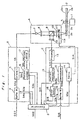
- Fig. 1 is a block diagram of an optical data recording device comprising a function which determines the irradiation conditions according to a method of the present invention. The operation of each component part thereof is described first below.
- This recording device comprises a spindle motor 1 which rotates an optical disk 2, an optical section A for focusing a laser beam on the optical disk 2, a data recording section B which modulates the laser beam, and a playback control section C which reads the data from the optical disk 2 and controls the laser spot.
- the operation of each circuit is managed by a controller 3.
- the optical disk 2 comprises a substrate 2a and a recording layer 2b on the substrate 2a.
- the surface of the substrate 2a comprises a groove and land structure guide track for tracking, or an address signal for recording position detection.
- the optical disk 2 comprises separately from the data area 2c to which the data signal is recorded a test area 2d for setting the light irradiation conditions.
- the material of the substrate 2a may be polymethyl methacrylate (PMMA), polycarbonate (PC), or a similar resin, or glass.
- the recording layer 2b to which the signal is recorded by means of light irradiation phase changes may be a GeTe, GeSbTe, InSe, InSeTlCo, GeSnTeAu, GeSbTeSe, SeSnTeO, SeTeS, or similar amorphous-crystalline state phase change material, or an InSb, AgZn, or similar crystalline-crystalline phase change material.
- TbFeCo, GdTbFe, and similar optomagnetic recording materials can also be used.
- the recording procedure in a regular mode after the irradiation conditions are set is defined below.
- the data signal SO1 recorded to the optical disk 2 is input to the data recording section B, which converts the electrical data signal to a power modulated optical signal, and stored initially to buffer memory 4.
- the buffer memory 4 outputs a data signal S4a to the drive circuit 5 at a timing determined according to a gate signal S3a from the controller 3.
- the drive circuit 5 generates a modulated current S5 according to the gate signal S4a and the conditions from the recording setting device 6, and drives the semiconductor laser 7. From the semiconductor laser 7 is generated a light beam power modulated between a peak power Pp and a bias power Pb.
- the light of the semiconductor laser 7 is regulated to a parallel beam by the collimeter lens 8, passed through a polarization beam splitter 9 and 1/4-wave plate 10, and focused by objective lens 11 to an approximately 10 ⁇ m spot diameter, which is the wavelength limit, on the recording thin-film 2b of the optical disk 2.
- a recording mark amorphous state
- a recording mark corresponding to the data signal as shown in Fig. 9 (c) is formed on the recording thin-film 2b, thus recording the signal.
- a continuous beam at a constant read power level Pr is irradiated to the optical disk 2.
- the reflected light from the recording thin-film 2b passes through the objective lens 11 and 1/4-wave plate 10, is reflected by the polarization beam splitter 9 and is thus incident upon the light detector 12.
- the signal resulting from optoelectric conversion by the light detector 12 is amplified by the preamplifier 13 in the playback control section C.
- the playback control section C converts the low frequency component of the preamplifier signal S13 to a control signal S14, and drives the voice coil 11a supporting the objective lens 11 for tracking and focusing the laser spot on the optical disk.
- the demodulation circuit 15 uses the high frequency component of the signal from the preamplifier 13 to demodulate the data signal resulting from the recording mark formed on the optical disk 2.
- the demodulated data signal S15a is temporarily stored in the buffer memory 16, and the data signal S16 is output to an external device according to the signal S3c specified from the controller.
- the device as thus described can thereby record a data signal to an optical disk and read the signal from the recorded area of the disk.
- the controller 3 By first inputting to the controller 3 a reference signal S02 which shows that factors causing a change in the condition of the optical disk have occurred, the operation for setting the irradiation conditions of the optical disk is started.
- the controller 3 outputs irradiation conditions setting mode signals S3b and S3a to the recording setting device 6 and the servo 14, respectively.
- the servo 14 moves the position of the laser beam to the test area 2d, sequentially reads various recording patterns from the pattern generator 17 by the recording setting device 6, and operates the drive circuit 5 according to these recording patterns. As a result, a recording marks which differ according to the irradiation conditions are formed on the optical disk.
- the irradiation conditions of the recording marks are detected by the DC component of the preamplifier output signal S13 by means of the reflectivity measuring device 19, and the optimum irradiation conditions are determined by the controller 3 through a process of adapting the signal S19, which represents the results of the reflectivity measurement, to the irradiation conditions.
- the DC component of the output signal can also be a sum signal of the tracking signal, which is one of the servo signals for the optical disk, or a sum signal of the focusing signal.
- the error correction signal S15b generated in the data demodulation process and output from the demodulation circuit 15 can be detected by the error detector 18, and the optimum irradiation conditions can be determined by adapting the error signal S18 and the irradiation conditions.
- the irradiation conditions are reset by generating the reference signal SO2 used in setting the irradiation conditions when factors which change the irradiation conditions of the optical disk occur, or when errors are detected in the actual write/read operation.
- the actual operating conditions are defined so that the irradiation conditions set signal is generated when the optical disk is changed, when the disk drive is started, when the ambient temperature of the operating environment changes more than a predetermined amount, when a predetermined period of time has passed after the irradiation conditions are set, or when more than a predetermined number of errors are detected in the read signal.
- any changes in the disk or the drive or changes relating to both the disk and the drive can be controlled. Furthermore, by monitoring any changes in the temperature of the operating environment and the passage of time after the irradiation conditions are set, the temperature dependency of the recording medium and any changes in the control state of the drive can be controlled.
- the irradiation conditions can be set in real time according to a reference signal for setting the optical disk irradiation conditions, data can be reliably recorded under optimum irradiation conditions, and the reliability of the data recording device can be improved.
- Fig. 2 is a cross section of an optical disk used in a first embodiment of the present invention.
- a thin-film protective layer 2e of ZnS Over the polycarbonate substrate 2a are sequentially laminated a thin-film protective layer 2e of ZnS, a recording layer 2b of GeSbTe, a thin-film protective layer 2f of ZnS, and a thin-film reflective layer 2g of Au, with a polycarbonate protective plate 2h attached thereto by an adhesive 2i.
- This optical disk has been rotated at a linear velocity of 1.25 m/sec during recording tests conducted under various light irradiation conditions.
- Fig. 3 (a) a graph of the results of a typical test, curve A shows the C/N power dependency, and curve B shows the erasure rate power dependency.
- the C/N and erasure rate are commonly used as standards for a simple evaluation of the optical disk irradiation conditions; higher values indicate high signal quality and a correspondingly low probability of read errors in the data signal.
- Curve A plots the measured results of the C/N ratio at a 718-kHz modulation frequency, 5-mW constant bias power Pb, and variable peak power Pp.
- the above signals were then overwritten with a 196-kHz signal using a constant 10-mW peak power Pp and a variable bias power Pb, and the extinction rate of the initial 718-kHz signal component was measured as the erasure rate.
- the curves with the maximum C/N and erasure rate values of 10 mW and 5 mW, respectively, are shown in Fig. 3 (a). Specifically, it is shown in Fig. 3 that a good recording is possible with a 10-mW peak power Pp and 5-mW bias power Pb.
- Fig. 3 (b) is a graph showing the measured results of reflectivity when the same disk is irradiated with a continuous power (unmodulated) beam.
- Solid line C resulted from irradiation of the amorphous state
- dotted line D resulted from irradiation of the crystalline state.
- the reflectivity of the amorphous state is R0, and that of the crystalline state is R1.
- the shaded area E represents the range wherein reflectivity can be obtained, i.e., within this range reflectivity is dependent upon the pre-irradiation state because the laser power is low.
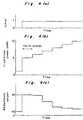
- Fig. 4 (a) is graph of the level of the control signal in the test area for setting the irradiation conditions which is obtained from the optical disk read signal, (b) shows the set power level of the irradiated laser beam, and (c) shows the change in reflectivity in the light irradiated area.
- the first step is to record the power conditions of the test recording specified by the controller to the pattern generator 17 through the recording setting device 6 by means of the control signal S3b from the controller for setting the irradiation conditions. For example, the values from 5 - 10 mW are set in 1 mW increments.
- the laser beam is then moved by the servo 14 to the test area 2d on the optical disk, and based on a preformatted signal (e.g., a control signal resulting from the pitch of a pit-land sequence provided in the substrate surface) from the test area, the optical disk is irradiated by the laser beam synchronized to the test start signal (a) according to the conditions indicated by the pattern generator 17.
- a preformatted signal e.g., a control signal resulting from the pitch of a pit-land sequence provided in the substrate surface
- the optical disk is irradiated with a DC light of the power level shown in Fig. 4 (b) by the test start signal (a).
- the drive circuit 5 is driven at a set power of 5 mW at this time, and the power is increased after a predetermined time (e.g., after a 1/10th rotation of the optical disk). As a result, signals are recorded to the disk at ten different power levels in one complete rotation of the disk.
- the laser power level is set to the read power level Pr, and the reflected light from the recorded portion is detected by the reflectivity measuring device 19.
- a signal which changes according to the irradiation conditions is obtained as shown in Fig. 4 (c) from the reflectivity measuring device 19, and by comparing this signal level by means of the circuit design or with another value by the controller 3, the power level Pd at which there is the greatest change in reflectivity to the change in laser power is obtained.
- Pd can be obtained by passing the reflectivity signal through a differentiation circuit and correlating the maximum time of the differentiation signal with the irradiation power.
- the power Pd level with the greatest change is 7 mW.
- the power level required for phase changes will differ with the recording material and the structure, but a constant relationship is established between the peak power and the erasure power levels within the range of variations in the recording device and changes during the manufacture of the optical disk which are objectives of the present invention.
- the relationship between the power Pd at which there is a large change in reflectivity, bias power Pb1 showing the maximum change in erasure rate, and the peak power Pp1 showing the maximum C/N rate can be approximated with the following equations.
- Pb1 n x Pd
- Pp1 m x Pd
- the optimum recording power Pp and Pb can be obtained from the power Pd obtained from the change in reflectivity as described hereinabove.
- Pb1 5 mW
- Pp1 10 mW
- Pd 7 mW
- These values m and n are stored in the pattern generator 17, or these conditions are recorded at the beginning of the test area 2d on the disk, and are read immediately before test signal recording.
- the optimum irradiation conditions for the current optical disk can thus be obtained from a device constructed as described above.
- a method of obtaining the optimum recording power by recording a digital signal and evaluating the demodulation signal is described next with reference to the same optical disk used in the first embodiment above.
- an EFM signal containing an audio signal and an error correction code CIRC cross interleave Reed-Solomon code
- CIRC cross interleave Reed-Solomon code
- Fig. 5 is a graph showing the measured results of errors at various power levels used to overwrite a signal at various recording power levels Pp and Pb.
- the error value used is the number of error correction codes C1, used in the EFM signal, generated per one second.
- Each curve is the result of measurements made for irradiation with incremental changes in the peak power Pp with a constant bias power Pb.
- the conditions under which the error count is smallest, indicating optimum irradiation conditions, are dependent upon the bias power Pb with a tendency for the optimum peak power Pp to change to a higher value with an increase in the bias power Pb.
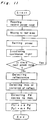
- the present embodiment is a method for determining the irradiation conditions of an optical disk using the characteristics shown in Fig. 5, and is described below with reference to the flow chart in Fig. 12.
- the first step is to record the power conditions of the test recording specified by the controller to the pattern generator 17 through the recording setting device 6 by means of the control signal S3b from the controller for setting the irradiation conditions. For example, fifteen conditions are set: bias power Pb levels 4, 5, and 6 mW, and peak power Pp levels 8, 9, 10, 11, and 12 mW.
- the laser beam is then moved by the servo 14 to the test area 2d on the optical disk, and based on a preformatted signal from the test area, the optical disk is irradiated by the laser beam synchronized to the test start signal according to the conditions indicated by the pattern generator 17.
- the irradiation conditions are thus sequentially changed to record the fifteen patterns.
- the read light from the recording section is demodulated by the demodulation circuit 15, resulting in a code signal from which the errors are detected by the error detector 18.
- the signal with the smallest number of errors is determined from the error detection result, thus making it possible to easily identify the position of the signal with the fewest errors, and making it possible, for example, to identify from the time passed after the start of recording the recording power levels Pp and Pb used to record the corresponding low error rate signal.
- the third embodiment relates to a method of obtaining an optimum irradiation pattern by detecting the edge position of the recording mark best suited to the pulse width modulation (PWM) method for reading and writing the signal.
- PWM pulse width modulation
- Most current optical disk recording methods are heat mode recording methods which record data by utilizing the phase change, reversal or change in the magnetic orientation of the recording thin-film resulting from a temperature increase caused by absorption of the light incident upon the thin film due to irradiation by a laser beam. Shown in Fig. 9 are the signal distortion, recording mark shape, and read signal wave resulting from heat mode recording.
- the heat accumulation effect characteristic of heat mode recording results in a higher temperature at the end of recording compared with the temperature at the beginning of recording. This results in an asymmetrical tear-shaped recording mark which is smaller at the beginning and larger at the end as shown in Fig. 9 (c).
- the binary signal (e) obtained from the read signal (d) obtained from the edge positions (start and end points) of this asymmetrical recording mark contains time errors J1, J2,and J3 when compared with the source recording signal (a), and when these time errors exceed a predetermined level, errors occur during demodulation.
- a multiple pulse signal recording method as illustrated in Fig. 10 can be used.
- the temperature of the irradiated portion can be controlled by irradiating a light pulse (b) comprising a string of plural pulses for each inverted signal (recording mark) of the data signal (a).
- a light pulse comprising a string of plural pulses for each inverted signal (recording mark) of the data signal (a).
- the temperature of the irradiated portion can be freely controlled.
- this multiple pulse method it is possible to concentrate the light energy at the recording start point, e.g.
- the optimum conditions of the modulation pattern (b) of this multiple pulse method may differ according to the optical disk and optical disk drive.
- a recording pattern optimized for these variable elements can be obtained.
- Fig. 6 is a block diagram of a device for obtaining an optimized irradiation pattern for the multiple pulse wave according to the recording layer
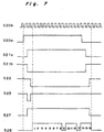
- Fig. 7 is a timing chart of the operation of this device.
- the modulation method of this device uses the EFM signal containing the error correction code CIRC as in the second embodiment of this invention.
- the primary feature of this circuit is storing in the pattern setting device a pulse string comprising forty-four pulses for the maximum pulse width 11T in this modulation method, and generating a pulse string of the required length from the beginning of the set pattern according to the pulse width of the input 3T to 11T pulse.
- the timing chart in Fig. 7 applies to the multiple pulse modulation of a 4T pulse.
- a start signal S23 is generated by data flip-flops DFF21 and DFF22 and the NAND circuit 23, and the parallel/serial out shift register PS/SR 24 operates.
- the PS/SR 24 calls the set pattern from the pattern setting device 25, and outputs the pattern one step at a time synchronized to the clock S20b.
- the pattern setting device 25 is a 44 x 15 bit ROM device in which fifteen patterns are stored, each pattern having the 44 pulses set HIGH or LOW for correspondence to the maximum pulse width (11T) of the EFM signal.
- the selector 26 selects the type of the pattern output from the pattern setting device 25 according to the control signal S6b from the recording setting device.
- a stop signal S27 is then output by the DFF 21, DFF 22, and NAND 27. This stop signal causes output from step 17 (inclusive) from the PS/SR 24 to stop, resulting in the pulse string of signal S24. It is to be noted that after the pulse string and clock S20b are synchronized again, the DFF 28 outputs the pulse string signal S28 to the drive circuit 5. Finally, a light output as shown in Fig.
- a pulse string can be obtained for pulses of all widths from EFM signals 3T to 11T, and the pulse pattern can be selected from among fifteen different patterns.
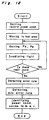
- the operation of this embodiment is described next with reference to the flow chart in Fig. 13.
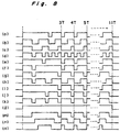
- the first step is to record the patterns of the possible multiple pulse patterns, e.g., the fifteen different patterns as shown in Fig. 8, specified by the controller to the pattern setting means 17 through the recording setting device 6 by means of the control signal S3b from the controller for setting the irradiation conditions.
- the laser beam is then moved by the servo 14 to the test area 2d on the optical disk, and based on a preformatted signal from the test area, the optical disk is irradiated by the laser beam synchronized to the test start signal according to the conditions indicated by the pattern setting means 17.
- the disk is irradiated by the laser beam for a constant period according to the pattern shown in Fig. 8 (a), followed by recording at a second set of irradiation conditions according to the pattern shown in Fig. 8 (b).
- the irradiation conditions are thus sequentially changed to record the fifteen patterns.
- the light read from the recording section is demodulated by the demodulation circuit 15, resulting in a code signal from which the error quantity is detected by the error detector 18.
- the signal with the smallest number of errors is determined from the error detection result, and the irradiation pattern can be identified from the recording time from the start of recording of the signal with the smallest number of errors.
- the methods optimized either the pattern or the irradiation power, but irradiation conditions with even higher precision can be set by combining an optimized irradiation power and recording pattern. Furthermore, in the present invention the completion of one complete range of irradiation conditions recorded to the test recording area within one revolution of the disk has been used as one standard, but it is desirable for the irradiation conditions to be set as required, including tests completed in less time or when it is necessary to set a precise high power level.
- evaluation of the error correction quantity was the only method used for evaluation of the data read signal, but other methods, including comparison of jitter in the demodulated signal, can be used to obtain the same effect.
- a phase-change optical disk medium was used as the recording medium, but the present invention is also effective with heat mode recording methods, and particularly with pulse width modulation recording methods.
Landscapes
- Physics & Mathematics (AREA)
- Optics & Photonics (AREA)
- Optical Recording Or Reproduction (AREA)
- Optical Head (AREA)
Claims (12)
- Verfahren zum Aufzeichnen eines Datensignals durch eine Einrichtung (A) einer Lichtstrahlabgabe auf ein Aufzeichnungsmedium (2), welches umkehrbar zwischen optisch unterscheidbaren Zuständen entsprechend bestimmter Lichtabstrahlungsaufzeichnungsenergiepegel wechselt, wobei das Verfahren die folgenden aufeinanderfolgenden Schritte umfaßt:a) Abstrahlen einer Reihe von Aufzeichnungslichtstrahlen mit unterschiedlichen Aufzeichnungsenergiepegeln vor Beginn der Aufzeichnung des Datensignals auf dem Aufzeichnungsmedium (2);b) Abstrahlen eines Leselichtstrahles auf das Aufzeichnungsmedium, auf welches die Reihe von Aufzeichnungslichtstrahlen abgestrahlt wurde;c) Erfassen der Menge des reflektierten oder durchfallenden Leselichts von dem oder durch das Aufzeichnungsmedium (2);d) Vergleichen der Ergebnisse der Erfassung für unterschiedliche Aufzeichnungsenergiepegel miteinander;e) Bestimmen eines optimalen Energiepegels des Lichtstrahles zum Aufzeichnen des Datensignals auf dem Aufzeichnungsmedium (2), basierend auf Ergebnissen des Vergleichs, wobei die Bestimmung des optimalen Aufzeichnungsenergiepegels des Lichtstrahles ausgeführt wird durch Bestimmen eines Energiepegels als ein Referenzenergiepegel, bei welchem die Änderung in der Menge des reflektierten oder durchfallenden Lichts als eine Funktion der Aufzeichnungsenergie ein Maximum wird, wobei der Referenzenergiepegel mit vorbestimmten konstanten Werten multipliziert wird und die als das Ergebnis der Multiplikation erhaltenen Werte als die optimalen Energiepegel bezeichnet werden; undf) Aufzeichnen des Datensignals unter Verwendung des optimalen Aufzeichnungsenergiepegels.
- Verfahren nach Anspruch 1, bei welchem jeder Strahl der Reihe von Lichtstrahlen ein kontinuierlicher Strahl eines konstanten Energiepegels für ein konstantes Zeitintervall ist.
- Verfahren nach Anspruch 1, bei welchem die Abstrahlung der Reihe von Lichtstrahlen in einem anderen Bereich als dem Daten-Schreib-Bereich des Aufzeichnungsmediums (2) ausgeführt wird.
- Verfahren nach Anspruch 1, welches weiterhin umfaßt:- Erfassen, wann eine optische Platte als Aufzeichnungsmedium (2) ausgetauscht wird, wann ein vorbestimmter Zeitabschnitt verstrichen ist, seit die Aufzeichnungsenergiepegel eingestellt wurden, oder wann die Umgebungstemperatur der Betriebsumgebung sich um mehr als einen vorbestimmten Betrag verändert;- Ausführen der Schritte a) bis e), wenn solch ein Ereignis erfaßt wurde.
- Verfahren zum Aufzeichnen eines Datensignals durch die Einrichtung einer Lichtstrahlabgabe auf ein Aufzeichnungsmedium (2), welches umkehrbar zwischen optisch unterscheidbaren Zuständen entsprechend bestimmter Lichtabstrahlungsaufzeichnungsenergiepegel wechselt, wobei das Verfahren die folgenden aufeinanderfolgenden Schritte umfaßt:a) Aufzeichnen eines Testsignals durch Abstrahlen einer Reihe von Lichtstrahlen mit unterschiedlichen Aufzeichnungsenergiepegeln vor dem Beginn des Aufzeichnens des Datensignals auf dem Aufzeichnungsmedium (2);b) Abstrahlen eines Leselichtstrahls auf das Aufzeichnungsmedium, auf das die Reihe von Aufzeichnungslichtstrahlen abgestrahlt wurde;c) Erfassen der Menge des reflektierten oder durchfallenden Leselichts von dem oder durch das Aufzeichnungsmedium zum Wiedergeben des Testsignals;d) Messen der Anzahl der Fehler des wiederhergestellten Testsignals für die verschiedenen Aufzeichnungsenergiepegel;e) Vergleichen der Ergebnisse der Messung für die entsprechenden Aufzeichnungsenergiepegel miteinander;f) Bestimmen optimaler Aufzeichungsenergiepegel des Lichtstrahles zum Aufzeichnen des Datensignales auf dem Aufzeichnungsmedium (2), basierend auf Ergebnissen des Vergleichs, in welchem die optimalen Aufzeichnungsenergiepegel des Lichtstrahles bei Energiepegeln festgelegt wurden, bei welchen die Fehlermenge minimal ist; undg) Aufzeichnen des Datensignals unter Verwendung des optimalen Aufzeichnungsenergiepegels.
- Verfahren nach Anspruch 5, bei welchem die Abstrahlung der Reihe von Lichtstrahlen mit wenigstens zwei Modulationsmustern ausgeführt wird, die aus mehreren sequentiellen Impulsen für jede Aufzeichnungsmarke bestehen, die auf dem Aufzeichnungsmedium zu bilden ist.
- Verfahren nach Anspruch 5, bei welchem die Abstrahlung der Reihe von Lichtstrahlen in einem anderen Bereich als dem Daten-Schreib-Bereich des Aufzeichnungsmediums ausgeführt wird.
- Verfahren nach Anspruch 5, welches weiterhin umfaßt:- Erfassen, wann eine optische Platte als Aufzeichnungsmedium ausgetauscht wird, wann in dem Lesesignal mehr als eine vorbestimmte Anzahl von Fehlern erfaßt wird, wann das Plattenlaufwerk gestartet wird, wann ein vorbestimmter Zeitabschnitt verstrichen ist, seit die Aufzeichnungsenergiepegel eingestellt wurden, oder wann sich die Umgebungstemperatur der Betriebsumgebung um mehr als einen vorbestimmten Betrag verändert;- Ausführen der Schritte a) bis f), wenn solch ein Ereignis erfaßt wurde.
- Verfahren zum Aufzeichnen eines Datensignals auf einem Aufzeichnungsmedium, welches umkehrbar zwischen optisch unterscheidbaren Zuständen entsprechend bestimmten Lichtabstrahlungsaufzeichnungsenergiepegeln wechselt, wobei das Verfahren die folgenden aufeinanderfolgenden Schritte umfaßt:a) Vorbereiten mehrerer verschiedener Abstrahlungsmuster von Aufzeichnungsimpulsen;b) aufeinanderfolgendes Abstrahlenderunterschiedlichen Abstrahlungsmuster auf den Aufzeichungsbereich des Aufzeichnungsmediums (2) vor dem Beginn der Aufzeichnung des Datensignals;c) Abstrahlen eines Leselichtstrahles auf das Aufzeichungsmedium, auf dem die Muster aufgezeichnet wurden;d) Erfassen der Menge des reflektierten oder durchfallenden Lichts von dem oder durch das Aufzeichnungsmedium für die unterschiedlichen Abstrahlungsmuster;e) Messen einer Fehlermenge des jeweils erfaßten reflektierten oder durchfallenden Lichts;f) Vergleichen der Ergebnisse der Messung für die entsprechenden Muster miteinander;g) Bestimmen von einem der verschiedenen Abstrahlungsmuster, bei welchem die Fehlermenge minimal ist, als optimales Abstrahlungsmuster zum Aufzeichnen des Datensignales; undh) Aufzeichnen des Datensignales unter Verwendung des optimalen Abstrahlungsmusters.
- Verfahren nach Anspruch 9, bei welchem Daten zum Erzeugen der verschiedenen Abstrahlungsmuster der Aufzeichnungsimpulse in einem Speicher gespeichert werden und eine aufeinanderfolgende Abstrahlung der verschiedenen Abstrahlungsmuster durch sequentielles Selektieren der in dem Speicher gespeicherten Daten ausgeführt wird.
- Verfahren nach Anspruch 9, bei welchem die sequentielle Abstrahlung der unterschiedlichen Abstrahlungsmuster in einem anderen Bereich ausgeführt wird als dem Aufzeichnungsbereich, in welchem das Datensignal aufgezeichnet wird.
- Verfahren nach Anspruch 9, welches weiterhin umfaßt:- Erfassen, wann eine optische Platte als Aufzeichnungsmedium ausgetauscht wird, wann mehr als eine vorbestimmte Anzahl von Fehlern in dem Lesesignal erfaßt wird, wann das Plattenlaufwerk gestartet wird, wann ein vorbestimmter Zeitabschnitt verstrichen ist, seit die Aufzeichnungsenergiepegel eingestellt wurden, oder wann sich die Umgebungstemperatur der Betriebsumgebung um mehr als einen vorbestimmten Betrag ändert;- Ausführen der Schritte a) bis g), wenn solch ein Ereignis erfaßt wurde.
Applications Claiming Priority (2)
| Application Number | Priority Date | Filing Date | Title |
|---|---|---|---|
| JP63166/90 | 1990-03-14 | ||
| JP6316690 | 1990-03-14 |
Publications (3)
| Publication Number | Publication Date |
|---|---|
| EP0446892A2 EP0446892A2 (de) | 1991-09-18 |
| EP0446892A3 EP0446892A3 (en) | 1992-12-16 |
| EP0446892B1 true EP0446892B1 (de) | 1997-06-04 |
Family
ID=13221391
Family Applications (1)
| Application Number | Title | Priority Date | Filing Date |
|---|---|---|---|
| EP91103832A Expired - Lifetime EP0446892B1 (de) | 1990-03-14 | 1991-03-13 | Verfahren zur optischen Aufzeichnung von Daten auf einem Medium |
Country Status (4)
| Country | Link |
|---|---|
| US (1) | US5305297A (de) |
| EP (1) | EP0446892B1 (de) |
| JP (1) | JP2797733B2 (de) |
| DE (1) | DE69126349T2 (de) |
Families Citing this family (45)
| Publication number | Priority date | Publication date | Assignee | Title |
|---|---|---|---|---|
| US5590111A (en) * | 1990-06-29 | 1996-12-31 | Hitachi, Ltd. | Method of controlling recording of optical records |
| JPH0469802A (ja) * | 1990-07-11 | 1992-03-05 | Sony Corp | 磁気変調コイル駆動回路 |
| JP3039056B2 (ja) * | 1991-11-25 | 2000-05-08 | ソニー株式会社 | 追記型光ディスク記録装置 |
| JPH0644565A (ja) * | 1992-07-24 | 1994-02-18 | Sony Corp | 光デイスク装置 |
| JP2835250B2 (ja) * | 1992-08-10 | 1998-12-14 | シャープ株式会社 | 光ディスク記録再生装置における光量制御装置 |
| JP3259204B2 (ja) * | 1992-10-21 | 2002-02-25 | 株式会社ニコン | 光記録方法及び光記録のパルストレイン条件決定方法 |
| EP0594425A3 (en) * | 1992-10-21 | 1996-10-09 | Nippon Kogaku Kk | Pulse train condition/heat shut off condition determination method and apparatus for optical recording, and optical recording method and apparatus |
| EP0595625A3 (en) * | 1992-10-28 | 1996-05-22 | Nippon Kogaku Kk | Prepulse condition/heat shut off condition determination method and apparatus for optical recording, and optical recording method and apparatus |
| JPH06301978A (ja) * | 1992-10-28 | 1994-10-28 | Nikon Corp | 光記録のプリパルス条件及び熱遮断条件決定方法、 同決定装置、光記録方法及び光記録装置 |
| US5610879A (en) * | 1993-03-05 | 1997-03-11 | Matsushita Electric Industrial Co. Ltd. | Optical reproducing device, optical reproducing method using the same, and optical record medium used in the same |
| JP2812636B2 (ja) * | 1993-04-22 | 1998-10-22 | 株式会社日立製作所 | 光学的記録装置 |
| BE1007029A3 (nl) * | 1993-04-22 | 1995-02-21 | Koninkl Philips Electronics Nv | Werkwijze voor het afleiden van een kwaliteitssignaal uit een uitgelezen signaal, alsmede een optekeninrichting en een uitleesinrichting waarin een dergelijke werkwijze wordt toegepast. |
| JP3240016B2 (ja) * | 1993-05-11 | 2001-12-17 | ソニー株式会社 | 光デイスク装置及び光デイスク装置の評価方法 |
| JP2643780B2 (ja) * | 1993-07-23 | 1997-08-20 | 日本電気株式会社 | 情報記録再生装置 |
| JP2827855B2 (ja) * | 1993-11-12 | 1998-11-25 | ヤマハ株式会社 | 光ディスク記録装置 |
| US5495466A (en) * | 1994-01-10 | 1996-02-27 | Eastman Kodak Company | Write verification in an optical recording system by sensing mark formation while writing |
| JP3231533B2 (ja) * | 1994-01-31 | 2001-11-26 | 株式会社日立製作所 | 光学的情報記録方法 |
| JP2643883B2 (ja) * | 1994-04-15 | 1997-08-20 | 日本電気株式会社 | 相変化光ディスクの初期化方法 |
| US5450383A (en) * | 1994-05-26 | 1995-09-12 | International Business Machines Corporation | Monitoring and adjusting laser write power in an optical disk recorder using pulse-width modulated power level checking signals |
| US5648952A (en) * | 1994-09-28 | 1997-07-15 | Ricoh Company, Ltd. | Phase-change optical disc recording method and apparatus, and information recording apparatus and recording pre-compensation method |
| US5726954A (en) * | 1995-04-10 | 1998-03-10 | Nikon Corporation | Optical recording method and apparatus |
| EP0737969B1 (de) * | 1995-04-10 | 2001-09-05 | Nikon Corporation | Optische Aufzeichnungsverfahren und optisches Aufzeichnungsgerät |
| JPH0969246A (ja) * | 1995-08-30 | 1997-03-11 | Canon Inc | 光学的情報記録再生装置 |
| US5825724A (en) * | 1995-11-07 | 1998-10-20 | Nikon Corporation | Magneto-optical recording method using laser beam intensity setting based on playback signal |
| US5831943A (en) * | 1995-11-07 | 1998-11-03 | Nikon Corporation | Stabilized overwriteable optical recording method using laser beam intensity settings |
| US5808972A (en) * | 1995-12-28 | 1998-09-15 | Nikon Corporation | Stabilized overwriteable optical recording method using laser beam intensity settings |
| KR0179259B1 (ko) * | 1996-04-13 | 1999-04-15 | 구자홍 | 상변화형 광기록매체 및 그의 제조방법 |
| JP3457463B2 (ja) * | 1996-04-26 | 2003-10-20 | 富士通株式会社 | 光学的記憶装置 |
| JP3259642B2 (ja) * | 1996-08-14 | 2002-02-25 | ヤマハ株式会社 | 光ディスク記録方法 |
| TW382703B (en) * | 1997-03-14 | 2000-02-21 | Hitachi Ltd | Signal recording method, phase difference detecting circuit, and information apparatus |
| JP4272279B2 (ja) | 1998-09-28 | 2009-06-03 | パナソニック株式会社 | 光学的情報記録装置、光学的情報記録媒体および光学的情報記録方法 |
| CN1190779C (zh) * | 1999-03-19 | 2005-02-23 | 松下电器产业株式会社 | 光学信息记录方法和使用该方法在光学信息记录媒体中进行信息记录的光学信息记录装置 |
| KR100579454B1 (ko) * | 1999-04-13 | 2006-05-12 | 엘지전자 주식회사 | 기록매체 및 이에 테스트 기록을 수행하는 장치 및 방법 |
| AU4783500A (en) | 1999-05-31 | 2000-12-18 | Matsushita Electric Industrial Co., Ltd. | Optical information recording method, optical information recording device and optical information recording medium |
| KR100322601B1 (ko) | 1999-06-18 | 2002-03-18 | 윤종용 | 광디스크 기록 방법, 광디스크 기록 장치의 제어 방법 및 이에 적합한 광디스크 기록 장치 |
| JP3768089B2 (ja) * | 2000-11-15 | 2006-04-19 | 三洋電機株式会社 | 光ディスク記録再生装置のレーザー出力設定方法 |
| JP3632617B2 (ja) * | 2001-05-24 | 2005-03-23 | ヤマハ株式会社 | 光ディスク記録方法およびその装置 |
| EP1421580A1 (de) * | 2001-08-24 | 2004-05-26 | Koninklijke Philips Electronics N.V. | Aufzeichnungsverfahren und -vorrichtung für optischen aufzeichnungsträger |
| JP2007528574A (ja) * | 2004-03-10 | 2007-10-11 | コーニンクレッカ フィリップス エレクトロニクス エヌ ヴィ | 記録担体の情報層にマークを記録する方法及び装置 |
| US10857722B2 (en) | 2004-12-03 | 2020-12-08 | Pressco Ip Llc | Method and system for laser-based, wavelength specific infrared irradiation treatment |
| US7425296B2 (en) | 2004-12-03 | 2008-09-16 | Pressco Technology Inc. | Method and system for wavelength specific thermal irradiation and treatment |
| JP2006277800A (ja) * | 2005-03-28 | 2006-10-12 | Taiyo Yuden Co Ltd | 光情報記録装置および方法および信号処理回路 |
| JP2007299470A (ja) * | 2006-04-28 | 2007-11-15 | Fujitsu Ltd | 記録媒体および記録媒体製造方法 |
| JP4523583B2 (ja) * | 2006-12-27 | 2010-08-11 | 太陽誘電株式会社 | データ記録評価方法及び光ディスク記録再生装置 |
| CN121417162A (zh) | 2015-09-01 | 2026-01-27 | 派拉斯科Ip有限责任公司 | 集成式电力供应与控制系统及方法 |
Family Cites Families (19)
| Publication number | Priority date | Publication date | Assignee | Title |
|---|---|---|---|---|
| JPS58143444A (ja) * | 1982-02-19 | 1983-08-26 | Fujitsu Ltd | 光学式情報記録装置 |
| JPS5998335A (ja) * | 1982-11-27 | 1984-06-06 | Canon Inc | 情報記録再生装置 |
| JPS60247836A (ja) * | 1984-05-22 | 1985-12-07 | Nippon Gakki Seizo Kk | 光学式情報再生装置 |
| JPS61165825A (ja) * | 1985-01-17 | 1986-07-26 | Olympus Optical Co Ltd | 光学的情報記録方法 |
| JPH0756734B2 (ja) * | 1985-05-27 | 1995-06-14 | 松下電器産業株式会社 | 情報記録再生装置 |
| US4937799A (en) * | 1985-12-13 | 1990-06-26 | Canon Kabushiki Kaisha | Method and apparatus for setting light quantity most suitable for reproducing information from an optical recording medium |
| EP0243976B1 (de) * | 1986-05-02 | 1996-09-04 | Hitachi, Ltd. | Methode zur Aufzeichnung, Wiedergabe und zum Löschen von Informationen und Dünnfilm zur Aufzeichnung von Informationen |
| JP2609593B2 (ja) * | 1986-10-24 | 1997-05-14 | 株式会社日立製作所 | ディスク媒体の記録方法及びディスク装置 |
| JPS63121130A (ja) * | 1986-11-07 | 1988-05-25 | Matsushita Electric Ind Co Ltd | 光情報記録再生装置 |
| NL8800223A (nl) * | 1987-04-21 | 1988-11-16 | Philips Nv | Systeem voor het registreren van een informatiesignaal, alsmede een registratiedrager en registratieinrichting voor toepassing in het systeem. |
| EP0289004B1 (de) * | 1987-04-28 | 1994-03-23 | Sharp Kabushiki Kaisha | Aufzeichnungs- und Wiedergabegerät |
| JP2576521B2 (ja) * | 1987-08-03 | 1997-01-29 | ブラザー工業株式会社 | 光磁気ディスク装置 |
| NL8702904A (nl) * | 1987-12-03 | 1989-07-03 | Philips Nv | Werkwijze en inrichting voor het optekenen van informatie op een registratiedrager, alsmede een inrichting voor het lezen van de opgetekende informatie. |
| JP2826108B2 (ja) * | 1988-06-24 | 1998-11-18 | シャープ株式会社 | 光記録再生装置 |
| US5126994A (en) * | 1988-11-29 | 1992-06-30 | Sony Corporation | Method and apparatus for controlling and detecting recording laser beam |
| US5043971A (en) * | 1989-09-28 | 1991-08-27 | Tandy Corporation | Method and apparatus for pre-compensation in an optical disc |
| JPH03116534A (ja) * | 1989-09-29 | 1991-05-17 | Toshiba Corp | 光ディスク装置 |
| US5050156A (en) * | 1989-10-25 | 1991-09-17 | Eastman Kodak Company | Method and apparatus for calibrating the writing power applied to an optical media |
| JPH03165825A (ja) * | 1989-11-27 | 1991-07-17 | Mitsubishi Materials Corp | 混合装置 |
-
1991
- 1991-03-01 JP JP3035878A patent/JP2797733B2/ja not_active Expired - Lifetime
- 1991-03-13 DE DE69126349T patent/DE69126349T2/de not_active Expired - Lifetime
- 1991-03-13 US US07/668,478 patent/US5305297A/en not_active Expired - Lifetime
- 1991-03-13 EP EP91103832A patent/EP0446892B1/de not_active Expired - Lifetime
Also Published As
| Publication number | Publication date |
|---|---|
| US5305297A (en) | 1994-04-19 |
| DE69126349D1 (de) | 1997-07-10 |
| JP2797733B2 (ja) | 1998-09-17 |
| EP0446892A2 (de) | 1991-09-18 |
| EP0446892A3 (en) | 1992-12-16 |
| DE69126349T2 (de) | 1997-12-11 |
| JPH04212720A (ja) | 1992-08-04 |
Similar Documents
| Publication | Publication Date | Title |
|---|---|---|
| EP0446892B1 (de) | Verfahren zur optischen Aufzeichnung von Daten auf einem Medium | |
| CA2020243C (en) | Optical information recording method and recording apparatus | |
| KR100294555B1 (ko) | 신호기록방법,위상차검출회로및정보장치 | |
| US5216657A (en) | Method and apparatus for timing variable optical information recording | |
| EP0164131B1 (de) | Informationsaufzeichnungsplatte und Verfahren und Gerät zum Aufzeichnen/Wiedergeben von Informationen | |
| US6222814B1 (en) | Recording/reproducing apparatus and method for phase-change optical disc | |
| EP0109130B1 (de) | Gerät zur Regelung des Aufzeichnungsbündels in einem optischen Datenaufzeichnungsverfahren | |
| EP0552936A1 (de) | Vorrichtung und Verfahren zum Aufzeichnen auf einem optischen Aufzeichnungsträger | |
| KR100455717B1 (ko) | 시험삼아 써보기방법 및 이것을 이용한 광디스크장치 | |
| US5150351A (en) | Optical information recording apparatus for recording an input signal having variable width pulse duration and pulse spacing periods | |
| KR100218070B1 (ko) | 광학 데이터의 기록 및 판독 방법과 그 장치 | |
| KR100621567B1 (ko) | 광학적 정보 기록 방법, 광학적 정보 기록 장치 및 광학적정보 기록 매체 | |
| JPH10320777A (ja) | 記録方法、位相ずれ検出回路、及びそれらを用いた情報装置 | |
| JP2650357B2 (ja) | 光学情報記録部材の記録方法 | |
| US4806952A (en) | Information recording apparatus for recording/reproducing information by irradiating an information recording medium with an energy beam | |
| KR100211787B1 (ko) | 직접 오버라이트 자기광학 저장 장치 및 방법 | |
| EP0599389B1 (de) | Verfahren und Vorrichtung zur Aufzeichnung von Signalen auf einen Aufzeichnungsträger | |
| JPH06295439A (ja) | 光記録の記録方法 | |
| JPH03116442A (ja) | 光ディスク装置および光ディスク | |
| JP2778428B2 (ja) | 光ディスク装置 | |
| EP0594425A2 (de) | Verfahren und Vorrichtung zur Bestimmung der Impulsenzugsendbedingung/der Wärmezufuhrausschaltbedingung für optisches Aufzeichnen sowie Verfahren und Vorrichtung zur optischen Aufzeichnung | |
| JP3314565B2 (ja) | 光学情報記録媒体の記録・再生方法 | |
| US20060280111A1 (en) | Optical storage medium and optical recording method | |
| JPH09231571A (ja) | ライトテスト方法及び光学的情報記録再生装置 | |
| JPH11265509A (ja) | 光学的情報記録再生方法および光学的情報記録媒体 |
Legal Events
| Date | Code | Title | Description |
|---|---|---|---|
| PUAI | Public reference made under article 153(3) epc to a published international application that has entered the european phase |
Free format text: ORIGINAL CODE: 0009012 |
|
| 17P | Request for examination filed |
Effective date: 19910313 |
|
| AK | Designated contracting states |
Kind code of ref document: A2 Designated state(s): DE FR GB NL |
|
| PUAL | Search report despatched |
Free format text: ORIGINAL CODE: 0009013 |
|
| AK | Designated contracting states |
Kind code of ref document: A3 Designated state(s): DE FR GB NL |
|
| 17Q | First examination report despatched |
Effective date: 19950726 |
|
| GRAG | Despatch of communication of intention to grant |
Free format text: ORIGINAL CODE: EPIDOS AGRA |
|
| GRAH | Despatch of communication of intention to grant a patent |
Free format text: ORIGINAL CODE: EPIDOS IGRA |
|
| GRAH | Despatch of communication of intention to grant a patent |
Free format text: ORIGINAL CODE: EPIDOS IGRA |
|
| GRAA | (expected) grant |
Free format text: ORIGINAL CODE: 0009210 |
|
| AK | Designated contracting states |
Kind code of ref document: B1 Designated state(s): DE FR GB NL |
|
| REF | Corresponds to: |
Ref document number: 69126349 Country of ref document: DE Date of ref document: 19970710 |
|
| ET | Fr: translation filed | ||
| PLBE | No opposition filed within time limit |
Free format text: ORIGINAL CODE: 0009261 |
|
| STAA | Information on the status of an ep patent application or granted ep patent |
Free format text: STATUS: NO OPPOSITION FILED WITHIN TIME LIMIT |
|
| 26N | No opposition filed | ||
| REG | Reference to a national code |
Ref country code: GB Ref legal event code: IF02 |
|
| PGFP | Annual fee paid to national office [announced via postgrant information from national office to epo] |
Ref country code: FR Payment date: 20100324 Year of fee payment: 20 |
|
| PGFP | Annual fee paid to national office [announced via postgrant information from national office to epo] |
Ref country code: GB Payment date: 20100310 Year of fee payment: 20 |
|
| PGFP | Annual fee paid to national office [announced via postgrant information from national office to epo] |
Ref country code: NL Payment date: 20100316 Year of fee payment: 20 Ref country code: DE Payment date: 20100415 Year of fee payment: 20 |
|
| REG | Reference to a national code |
Ref country code: DE Ref legal event code: R071 Ref document number: 69126349 Country of ref document: DE |
|
| REG | Reference to a national code |
Ref country code: NL Ref legal event code: V4 Effective date: 20110313 |
|
| REG | Reference to a national code |
Ref country code: GB Ref legal event code: PE20 Expiry date: 20110312 |
|
| PG25 | Lapsed in a contracting state [announced via postgrant information from national office to epo] |
Ref country code: NL Free format text: LAPSE BECAUSE OF EXPIRATION OF PROTECTION Effective date: 20110313 |
|
| PG25 | Lapsed in a contracting state [announced via postgrant information from national office to epo] |
Ref country code: GB Free format text: LAPSE BECAUSE OF EXPIRATION OF PROTECTION Effective date: 20110312 |
|
| PG25 | Lapsed in a contracting state [announced via postgrant information from national office to epo] |
Ref country code: DE Free format text: LAPSE BECAUSE OF EXPIRATION OF PROTECTION Effective date: 20110313 |