EP0447083A1 - Chipausstosssystem für Chipverbinder - Google Patents
Chipausstosssystem für Chipverbinder Download PDFInfo
- Publication number
- EP0447083A1 EP0447083A1 EP91301753A EP91301753A EP0447083A1 EP 0447083 A1 EP0447083 A1 EP 0447083A1 EP 91301753 A EP91301753 A EP 91301753A EP 91301753 A EP91301753 A EP 91301753A EP 0447083 A1 EP0447083 A1 EP 0447083A1
- Authority
- EP
- European Patent Office
- Prior art keywords
- die
- head
- eject
- die eject
- centering
- Prior art date
- Legal status (The legal status is an assumption and is not a legal conclusion. Google has not performed a legal analysis and makes no representation as to the accuracy of the status listed.)
- Granted
Links
Images


Classifications
-
- H—ELECTRICITY
- H10—SEMICONDUCTOR DEVICES; ELECTRIC SOLID-STATE DEVICES NOT OTHERWISE PROVIDED FOR
- H10P—GENERIC PROCESSES OR APPARATUS FOR THE MANUFACTURE OR TREATMENT OF DEVICES COVERED BY CLASS H10
- H10P72/00—Handling or holding of wafers, substrates or devices during manufacture or treatment thereof
- H10P72/04—Apparatus for manufacture or treatment
- H10P72/0444—Apparatus for wiring semiconductor or solid-state device
Definitions
- the present invention relates to a die eject system for a hybrid die bonder, in particular an automatic hybrid die bonder.
- a hybrid die bonder is used for bonding semiconductor dice of a range of different types and, in particular, sizes to a substrate.
- the die is ejected from a die presentation system, a number of different types of which are known and used, and picked up by an appropriate tool.
- the choice of die presentation system is determined principally by the size of the die, and available die presentation systems include wafer rings, film frames and waffle packs, each of which is available in different sizes.
- the die presentation system is held in a holder which is transversed over a die eject head.
- Known die eject heads comprise a metal cap mounted on a bush.
- the metal cap is provided with one or more holes which extend through the thickness of the cap.
- One or more die eject needles are located within the bush, one needle being associated with each of the holes.
- the needles are mounted on a pin, and can be raised or lowered relative to the cap, so that the needle, in the raised position, projects by a predetermined amount through the hole, above the surface of the cap.
- the number of needles, and hence holes in the cap is varied depending on the size of the die to be handled, and is generally one, two, three or four.
- a similar series of operations has to be carried out if one of the needles becomes damaged or broken during operation of the machine.
- the present invention provides a die eject system for a hybrid die bonder, in particular an automatic hybrid die bonder.
- An automatic hybrid die bonder as shown in figure 1, comprises a die presentation system, shown generally at 104, a die eject station according to the present invention as shown generally at 104 and a die pick up and mounting system, which may be a die collet system (106) or an epoxy die bonder (108).
- a suitable die presentation system (102) is described and claimed in our copending UK Patent Application (Folio 15095) of even date herewith, and comprises a magazine (110) for storing a plurality of die presentation packages (112), a rotatable clamp assembly (114) comprising first and second clamp means (116,118) mounted on a rotatable support and each adapted to collect a selected die presentation package from the magazine (110), feed it to the die eject station (104) retrieve it from the die eject station after a predetermined number of dice have been ejected and return it to said magazine (110).
- the die presentation system (102) further comprises indexing means for indexing movement of the packages within the magazine (110) so that the selected package is located at a collection point for collection from the magazine.
- An automatic hybrid die bonder preferably comprises both a die collet mounting station (106) and an epoxy die bonding station (108).
- the die pick-up stage suitably comprises a tool exchange system such as that described and claimed in our copending UK Patent Application (Folio 15096) of even date herewith, which comprises a tool bank (120,122) comprising a plurality of tool holders (124,126) each fitted with a tool and adapted for pick-up by a head (128).
- the head (128) is mounted on a support and can be driven between the tool bank (120,122), the die eject station (104) according to the present invention and a die mounting station (106,108).
- the tool bank (120,122) can be driven to index a selected tool holder to a station at which it can be picked up by the head (128).
- the die eject system according to the present invention comprises a support, a plurality of die eject heads mounted on the support and means for indexing movement of the support to index the die eject heads successively into an operative position.
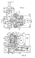
- a die eject assembly ( Figure 2) comprises five die eject heads (10) mounted on a support (12) which is rotatable about a central axis (A).
- the five die eject heads (10) are spaced equiangularly about the support (12) and each is removably mounted on a support bracket (14).
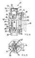
- a centering mechanism comprises a centering support (16) ( Figure 4) fitted with a centering cone (18) which locates in a matching hole (not shown) in the bracket (14), is attached to a housing (20) of the die eject head (10), in which is slideably located a needle holder (22) mounted on the upper end of a pin (24).
- the lower end of the pin (24) is attached to a spring loaded carrier (26), which is biased towards a floor (30) of the housing by a tension spring (28) mounted on an upper securing bolt (46) attached to the carrier (26) and a lower securing bolt (48) attached to the inside wall of the housing (20).
- a centering unit (32) is secured in the housing floor (30) and co-operates with a centering bush (34) as shown in Figure 3.
- a further centering pin (36) similarly locates in a pin centering unit (38).
- One or more die eject needles (40) are mounted in the needle holder (22) and secured by means of screws (not shown). Movement of the needle assembly comprising the needle or needles (40), needle holder (22), pin (24) and carrier (26) is guided by a mechanical guide (44) located within the housing (20).
- a cap (50) is secured to a bush (52) at the top of the housing (20) by means of a screw (54).
- the upper surface of the cap (50) is provided in known manner with a network of grooves (56), holes (58) being associated with each of the grooves (56). These holes (58) extend through the thickness of the cap (50) and communicate with the inside of the housing (20) for evacuation. Additional holes (60) similarly extend through the thickness of the cap (50), one such hole being associated with and positioned vertically above each die eject needle (40).
- a further centering pin (62) is mounted on the outside of the housing (20) by means of a block (64). This pin (62) is used in setting up the head outside the machine to determine the precise position of the needles relative to the fixed point of the pin, as will be explained in more detail later.
- the head (10) is mounted on a support (12) which is rotatable about an axis (A). When the head (12) is in the operative position, it is located with its centering unit (32) and centering pin (36) vertically above a centering bush (34) and a pin centering unit (38) respectively.
- the centering bush (34) is mounted on a plate (66) on which the pin centering unit (38) is also mounted.
- a vertical cylindrical bore is provided centrally in the centering bush (34) and a rod (68) is slideably located within the bore.
- a vacuum connection (70) is provided so that the housing (20) of the die eject head (10) can be evacuated.
- a stepping motor (72) is connected by means of a disc (74) to a block (76) on which the rod (68) is mounted and can be controlled to cause vertical movement of the rod (68).
- the five die eject heads (10) are mounted on a support (12) which is rotatable about a central axis (A).
- a motor (78) is engaged by means of planetary gears (not shown) with a toothed belt (82) to drive a shaft (84) connected to a parallel shaft (86) by means of a spur wheel (88).
- the support (12) is mounted on the shaft (86) and is rotatable therewith.
- two or more die eject heads (10) having the needle arrangements required for the particular dice to be handled, are mounted on the support (12). Prior to this mounting, the heads are inspected, and the x,y offset of the needles (40) relative to the pin (36) is recorded for each head. The offsets are then fed into the control system for the machine so that the exact location of needles is known, and the die presentation system can be suitably positioned so that a die is available for ejection.
- the support (12) is rotated by means of the motor (78) and associated gearing, so that the selected head (10) is in the operative position of the die bonder machine (100).
- the head (10) is lifted by the air cylinder (71) and associated gearing so that the upper surface of the cap (50) is positioned immediately below and in contact with the under surface of the wafer (102).
- the vacuum connection (70) is then released and the chamber of the die eject head evacuated.
- the under surface of the wafer (102) is held down on the upper surface of the cap (50) by means of the vacuum applied, through the holes (58) and communicating network of grooves (56).
- the needle assembly is then further raised against the spring (28) by the stepping motor (72) so that the needle or needles (40) project through the corresponding holes (60) in the top of the cap (50) by a predetermined amount.
- the die located above the needle or needles (40) is then ejected from the wafer (102) so that it can be picked up by the tool of the pick-up system (106, 108) and taken to the die collet station for mounting on a substrate.
- the movement of the needles and their speed can be programmed.
- FIG. 6 A second embodiment of a die eject assembly according to the invention is shown in Figure 6.
- an alternative centering mechanism for centering the die eject head (10) on the rod (68) is provided.
- Precise location of the die eject head (10) is achieved by means of a three point location system.
- Three spheres (90) are mounted, equiangularly spaced, in the upper surface (92) of the plate (66), in recesses (94) machined close to the outer edge of the upper surface.
- Three matching location points are provided on the lower surface of the head (10), spaced to mate with the spheres (90) when the head (10) is placed on the plate (66).
- the first of these location points is a concave surface, which determines the x-y position of the head (10) relative to the plate (66); the second is a flat surface which determines the height of the head relative to the plate and the third is a triangular prism which determines the angular rotation of the head relative to the plate.
Landscapes
- Die Bonding (AREA)
- Container, Conveyance, Adherence, Positioning, Of Wafer (AREA)
- Details Of Connecting Devices For Male And Female Coupling (AREA)
- Particle Formation And Scattering Control In Inkjet Printers (AREA)
Applications Claiming Priority (2)
| Application Number | Priority Date | Filing Date | Title |
|---|---|---|---|
| GB909006035A GB9006035D0 (en) | 1990-03-16 | 1990-03-16 | Die eject system for die bonder |
| GB9006035 | 1990-03-16 |
Publications (2)
| Publication Number | Publication Date |
|---|---|
| EP0447083A1 true EP0447083A1 (de) | 1991-09-18 |
| EP0447083B1 EP0447083B1 (de) | 1995-09-20 |
Family
ID=10672783
Family Applications (1)
| Application Number | Title | Priority Date | Filing Date |
|---|---|---|---|
| EP91301753A Expired - Lifetime EP0447083B1 (de) | 1990-03-16 | 1991-03-04 | Chipausstosssystem für Chipverbinder |
Country Status (6)
| Country | Link |
|---|---|
| US (1) | US5165521A (de) |
| EP (1) | EP0447083B1 (de) |
| JP (1) | JPH0774188A (de) |
| AT (1) | ATE128318T1 (de) |
| DE (1) | DE69113086T2 (de) |
| GB (1) | GB9006035D0 (de) |
Cited By (3)
| Publication number | Priority date | Publication date | Assignee | Title |
|---|---|---|---|---|
| EP0851489A3 (de) * | 1996-12-06 | 1999-12-15 | Texas Instruments Incorporated | Verbesserungen in oder in Beziehung zu integrierten Schaltungen |
| US7156602B2 (en) | 2001-11-08 | 2007-01-02 | F & K Delvotec Bondtechnick Gmbh | Mechanism for exchanging chip-carrier plates for use in a hybrid chip-bonding machine |
| CN113571429A (zh) * | 2021-09-28 | 2021-10-29 | 深圳市卓兴半导体科技有限公司 | 一种固晶方法及固晶机 |
Families Citing this family (8)
| Publication number | Priority date | Publication date | Assignee | Title |
|---|---|---|---|---|
| US6068104A (en) * | 1997-11-26 | 2000-05-30 | Jenoptik Aktiengesellschaft | Device for securing a moving object at a destination |
| US6926132B1 (en) * | 2002-11-01 | 2005-08-09 | Reagent Chemical & Research, Inc. | Hold down assembly, with tubular container transport apparatus and methodology incorporating the same |
| WO2004112100A1 (de) * | 2003-06-02 | 2004-12-23 | Amicra Microtechnologies Gmbh | Bondvorrichtung und bondverfahren |
| US7207430B2 (en) * | 2004-10-25 | 2007-04-24 | Ui Holding Company | Vacuum gripper for handling small components |
| JP4210280B2 (ja) * | 2005-09-01 | 2009-01-14 | 本田技研工業株式会社 | ワークのクランプ装置 |
| JP5941701B2 (ja) * | 2012-02-23 | 2016-06-29 | ファスフォードテクノロジ株式会社 | ダイボンダ |
| JP6000322B2 (ja) * | 2014-12-02 | 2016-09-28 | 富士機械製造株式会社 | ダイ供給装置 |
| US10281371B2 (en) | 2016-06-10 | 2019-05-07 | Met One Instruments, Inc. | Sequential air sampler with filter cassette magazine |
Citations (2)
| Publication number | Priority date | Publication date | Assignee | Title |
|---|---|---|---|---|
| US4526646A (en) * | 1983-03-03 | 1985-07-02 | Shinkawa Ltd. | Inner lead bonder |
| US4795518A (en) * | 1984-02-17 | 1989-01-03 | Burr-Brown Corporation | Method using a multiple device vacuum chuck for an automatic microelectronic bonding apparatus |
Family Cites Families (8)
| Publication number | Priority date | Publication date | Assignee | Title |
|---|---|---|---|---|
| US1344653A (en) * | 1919-12-05 | 1920-06-29 | Rosengren Anders Andersson | Device for the feeding of bottles or other vessels to machines intended for treating them |
| DE1126703B (de) * | 1957-09-14 | 1962-03-29 | Gauthier Gmbh A | Werkzeugmaschine mit um eine volle Umdrehung schaltbarem Werkstuecktraeger |
| US2956664A (en) * | 1958-09-26 | 1960-10-18 | Western Electric Co | Ejector mechanisms |
| US3037269A (en) * | 1959-04-22 | 1962-06-05 | Western Electric Co | Assembly apparatus |
| US3308921A (en) * | 1965-02-15 | 1967-03-14 | Leach Corp | Carriage |
| US3378129A (en) * | 1966-11-30 | 1968-04-16 | Internat Machinery Corp | Container handling system |
| GB1591158A (en) * | 1976-11-09 | 1981-06-17 | Cleamax Ltd | High speed can handling mechanism |
| US4358920A (en) * | 1980-06-04 | 1982-11-16 | Lotte Co., Ltd. | Apparatus for wrapping a sheet article |
-
1990
- 1990-03-16 GB GB909006035A patent/GB9006035D0/en active Pending
-
1991
- 1991-03-04 EP EP91301753A patent/EP0447083B1/de not_active Expired - Lifetime
- 1991-03-04 DE DE69113086T patent/DE69113086T2/de not_active Expired - Fee Related
- 1991-03-04 AT AT91301753T patent/ATE128318T1/de not_active IP Right Cessation
- 1991-03-13 JP JP4834491A patent/JPH0774188A/ja active Pending
-
1992
- 1992-06-18 US US07/900,559 patent/US5165521A/en not_active Expired - Lifetime
Patent Citations (2)
| Publication number | Priority date | Publication date | Assignee | Title |
|---|---|---|---|---|
| US4526646A (en) * | 1983-03-03 | 1985-07-02 | Shinkawa Ltd. | Inner lead bonder |
| US4795518A (en) * | 1984-02-17 | 1989-01-03 | Burr-Brown Corporation | Method using a multiple device vacuum chuck for an automatic microelectronic bonding apparatus |
Cited By (3)
| Publication number | Priority date | Publication date | Assignee | Title |
|---|---|---|---|---|
| EP0851489A3 (de) * | 1996-12-06 | 1999-12-15 | Texas Instruments Incorporated | Verbesserungen in oder in Beziehung zu integrierten Schaltungen |
| US7156602B2 (en) | 2001-11-08 | 2007-01-02 | F & K Delvotec Bondtechnick Gmbh | Mechanism for exchanging chip-carrier plates for use in a hybrid chip-bonding machine |
| CN113571429A (zh) * | 2021-09-28 | 2021-10-29 | 深圳市卓兴半导体科技有限公司 | 一种固晶方法及固晶机 |
Also Published As
| Publication number | Publication date |
|---|---|
| DE69113086T2 (de) | 1996-05-09 |
| EP0447083B1 (de) | 1995-09-20 |
| DE69113086D1 (de) | 1995-10-26 |
| ATE128318T1 (de) | 1995-10-15 |
| GB9006035D0 (en) | 1990-05-09 |
| US5165521A (en) | 1992-11-24 |
| JPH0774188A (ja) | 1995-03-17 |
Similar Documents
| Publication | Publication Date | Title |
|---|---|---|
| US4624050A (en) | Head for handling electrical components | |
| EP0050797B1 (de) | Automatischer Werkzeugwechsler mit innerem Werkzeugspeichermagazin | |
| US5165521A (en) | Die eject system for die bonder | |
| US4563800A (en) | Electrode tool storage magazine | |
| US4770599A (en) | Pick-up head for handling electric components | |
| EP0324002B1 (de) | Verdrehbarer aufnahme- und absetz-vakuumgreifkopf für plättchenbefestigungsapparat | |
| JPS63202098A (ja) | 部品供給手段 | |
| EP0906808A2 (de) | Verfahren zum Stapeln von Packen von Leiterplatten und entsprechende Vorrichtung zum Laden und Entladen von Packen für eine Werkzeugmaschine | |
| JP2808259B2 (ja) | チップ自動ローディング装置 | |
| US20030086775A1 (en) | Mechanism for exchanging chip-carrier plates for use in a hybrid chip-bonding machine | |
| US5799858A (en) | Die bonding device | |
| CN112295946A (zh) | 芯片自动分选系统 | |
| US20020192059A1 (en) | Methods and apparatus for transferring electrical components | |
| EP0447082B1 (de) | Chip-Zuführungssystem für Chipkontaktierer | |
| US4589608A (en) | Cassette loading apparatus | |
| EP0447087B1 (de) | Werkzeugauswechselsystem für Hybrid-Chipverbinder | |
| JP3097511B2 (ja) | チップの搭載装置 | |
| US20040216674A1 (en) | Wafer jar loader method, system and apparatus | |
| US5203659A (en) | Die presentation system for die bonder | |
| KR102187934B1 (ko) | 다이아몬드 파우더 정량 자동 패키징 시스템 | |
| JP3762083B2 (ja) | 電子部品打抜検査装置 | |
| US7604451B2 (en) | Feed mechanism and method for feeding minute items | |
| KR0117628Y1 (ko) | 반도체 제조장비의 매거진 구동장치 | |
| JPS5897844A (ja) | ダイ詰め換え装置 | |
| JPS6116535A (ja) | 半導体ペレツトのマウント装置 |
Legal Events
| Date | Code | Title | Description |
|---|---|---|---|
| PUAI | Public reference made under article 153(3) epc to a published international application that has entered the european phase |
Free format text: ORIGINAL CODE: 0009012 |
|
| AK | Designated contracting states |
Kind code of ref document: A1 Designated state(s): AT CH DE ES FR GB IT LI NL SE |
|
| 17P | Request for examination filed |
Effective date: 19911223 |
|
| RAP1 | Party data changed (applicant data changed or rights of an application transferred) |
Owner name: F & K DELVOTEC BONDTECHNIK GMBH |
|
| 17Q | First examination report despatched |
Effective date: 19940203 |
|
| GRAA | (expected) grant |
Free format text: ORIGINAL CODE: 0009210 |
|
| AK | Designated contracting states |
Kind code of ref document: B1 Designated state(s): AT CH DE ES FR GB IT LI NL SE |
|
| PG25 | Lapsed in a contracting state [announced via postgrant information from national office to epo] |
Ref country code: IT Free format text: LAPSE BECAUSE OF FAILURE TO SUBMIT A TRANSLATION OF THE DESCRIPTION OR TO PAY THE FEE WITHIN THE PRESCRIBED TIME-LIMIT;WARNING: LAPSES OF ITALIAN PATENTS WITH EFFECTIVE DATE BEFORE 2007 MAY HAVE OCCURRED AT ANY TIME BEFORE 2007. THE CORRECT EFFECTIVE DATE MAY BE DIFFERENT FROM THE ONE RECORDED. Effective date: 19950920 Ref country code: NL Free format text: LAPSE BECAUSE OF FAILURE TO SUBMIT A TRANSLATION OF THE DESCRIPTION OR TO PAY THE FEE WITHIN THE PRESCRIBED TIME-LIMIT Effective date: 19950920 Ref country code: ES Free format text: THE PATENT HAS BEEN ANNULLED BY A DECISION OF A NATIONAL AUTHORITY Effective date: 19950920 |
|
| REF | Corresponds to: |
Ref document number: 128318 Country of ref document: AT Date of ref document: 19951015 Kind code of ref document: T |
|
| ET | Fr: translation filed | ||
| REF | Corresponds to: |
Ref document number: 69113086 Country of ref document: DE Date of ref document: 19951026 |
|
| PG25 | Lapsed in a contracting state [announced via postgrant information from national office to epo] |
Ref country code: SE Effective date: 19951220 |
|
| NLV1 | Nl: lapsed or annulled due to failure to fulfill the requirements of art. 29p and 29m of the patents act | ||
| PG25 | Lapsed in a contracting state [announced via postgrant information from national office to epo] |
Ref country code: LI Effective date: 19960331 Ref country code: CH Effective date: 19960331 |
|
| PLBE | No opposition filed within time limit |
Free format text: ORIGINAL CODE: 0009261 |
|
| STAA | Information on the status of an ep patent application or granted ep patent |
Free format text: STATUS: NO OPPOSITION FILED WITHIN TIME LIMIT |
|
| 26N | No opposition filed | ||
| REG | Reference to a national code |
Ref country code: CH Ref legal event code: PL |
|
| REG | Reference to a national code |
Ref country code: GB Ref legal event code: IF02 |
|
| PGFP | Annual fee paid to national office [announced via postgrant information from national office to epo] |
Ref country code: GB Payment date: 20050223 Year of fee payment: 15 |
|
| PGFP | Annual fee paid to national office [announced via postgrant information from national office to epo] |
Ref country code: FR Payment date: 20050318 Year of fee payment: 15 |
|
| PG25 | Lapsed in a contracting state [announced via postgrant information from national office to epo] |
Ref country code: GB Free format text: LAPSE BECAUSE OF NON-PAYMENT OF DUE FEES Effective date: 20060304 |
|
| GBPC | Gb: european patent ceased through non-payment of renewal fee |
Effective date: 20060304 |
|
| REG | Reference to a national code |
Ref country code: FR Ref legal event code: ST Effective date: 20061130 |
|
| PG25 | Lapsed in a contracting state [announced via postgrant information from national office to epo] |
Ref country code: FR Free format text: LAPSE BECAUSE OF NON-PAYMENT OF DUE FEES Effective date: 20060331 |
|
| PGFP | Annual fee paid to national office [announced via postgrant information from national office to epo] |
Ref country code: AT Payment date: 20080320 Year of fee payment: 18 |
|
| PGFP | Annual fee paid to national office [announced via postgrant information from national office to epo] |
Ref country code: DE Payment date: 20080519 Year of fee payment: 18 |
|
| PG25 | Lapsed in a contracting state [announced via postgrant information from national office to epo] |
Ref country code: AT Free format text: LAPSE BECAUSE OF NON-PAYMENT OF DUE FEES Effective date: 20090304 |
|
| PG25 | Lapsed in a contracting state [announced via postgrant information from national office to epo] |
Ref country code: DE Free format text: LAPSE BECAUSE OF NON-PAYMENT OF DUE FEES Effective date: 20091001 |