EP0447087A1 - Système d'échange d'outil pour connecteur de puce hybride - Google Patents
Système d'échange d'outil pour connecteur de puce hybride Download PDFInfo
- Publication number
- EP0447087A1 EP0447087A1 EP91301769A EP91301769A EP0447087A1 EP 0447087 A1 EP0447087 A1 EP 0447087A1 EP 91301769 A EP91301769 A EP 91301769A EP 91301769 A EP91301769 A EP 91301769A EP 0447087 A1 EP0447087 A1 EP 0447087A1
- Authority
- EP
- European Patent Office
- Prior art keywords
- tool
- head
- die
- tool holder
- exchange system
- Prior art date
- Legal status (The legal status is an assumption and is not a legal conclusion. Google has not performed a legal analysis and makes no representation as to the accuracy of the status listed.)
- Granted
Links
Images
Classifications
-
- H—ELECTRICITY
- H10—SEMICONDUCTOR DEVICES; ELECTRIC SOLID-STATE DEVICES NOT OTHERWISE PROVIDED FOR
- H10P—GENERIC PROCESSES OR APPARATUS FOR THE MANUFACTURE OR TREATMENT OF DEVICES COVERED BY CLASS H10
- H10P72/00—Handling or holding of wafers, substrates or devices during manufacture or treatment thereof
- H10P72/04—Apparatus for manufacture or treatment
- H10P72/0444—Apparatus for wiring semiconductor or solid-state device
-
- Y—GENERAL TAGGING OF NEW TECHNOLOGICAL DEVELOPMENTS; GENERAL TAGGING OF CROSS-SECTIONAL TECHNOLOGIES SPANNING OVER SEVERAL SECTIONS OF THE IPC; TECHNICAL SUBJECTS COVERED BY FORMER USPC CROSS-REFERENCE ART COLLECTIONS [XRACs] AND DIGESTS
- Y10—TECHNICAL SUBJECTS COVERED BY FORMER USPC
- Y10S—TECHNICAL SUBJECTS COVERED BY FORMER USPC CROSS-REFERENCE ART COLLECTIONS [XRACs] AND DIGESTS
- Y10S33/00—Geometrical instruments
- Y10S33/01—Magnetic
Definitions
- the present invention relates to a tool exchange system for a die pick-up stage of a hybrid die bonder, in particular an automatic hybrid die bonder.
- a hybrid die bonder is used for bonding semiconductor dice of a range of different types, and in particular, sizes to a substrate.
- the die is supplied in an appropriate die presentation system, a number of different types of which are known and used, to a die eject station, at which individual dice are ejected from the die presentation system and picked up by an appropriate tool.
- the pick-up tool comprises one or more pairs of jaws held in a holder fixed in the machine.
- the tool jaws are changed. This has the disadvantage that there is a loss in operating time while the jaws are being changed, and the exact position and orientation of the jaws relative to a fixed reference point has to be determined on each occasion that the jaws are changed.
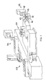
- An automatic hybrid die bonder as shown in Figure 1, comprises a die presentation system, shown generally at 102, a die eject station shown generally at 104 and a die pick up and mounting system, which may be a die collet system (106) or an epoxy print system (108), according to the present invention.
- a die presentation system shown generally at 102
- a die eject station shown generally at 104
- a die pick up and mounting system which may be a die collet system (106) or an epoxy print system (108), according to the present invention.
- a suitable die presentation system (102) is described and claimed in our co-pending UK Patent Application (Folio 15095) of even date herewith, and comprises a magazine (110) for storing a plurality of die presentation packages (112), a rotatable clamp assembly (114) comprising front and second clamp means (116,118) mounted on a rotatable support and each adapted to collect a selected die presentation package from the magazine (110), feed it to the die eject station (104), retrieve it from the die eject station after a predetermined number of dice have been ejected and return it to said magazine (110).
- the die presentation system (102) further comprises indexing means for indexing movement of the packages within the magazine (110) so that the selected package is located at a collection point for collection from the magazine.
- a die eject station (104) which suitably comprises a die eject system such as the die eject system described and claimed in our copending UK Patent Application (F.15094) of even date herewith, which system comprises a support, a plurality of die eject leads mounted on the support, and means for indexing movement of the support to index a die eject head into an operative position.
- the different die eject heads comprise different arrangements of die eject needles, each of which is suitable for ejecting a particular size or type of die.
- An automatic hybrid die bonder preferably comprises both a die collet mounting station (106) and a epoxy die bonding station (108).
- the die pick-up stage suitably comprises a tool exchange system according to the present invention.
- the present invention provides a tool exchange system for a hybrid die bonder, which system comprises
- the tool bank (c) preferably contains a plurality of tool holders, each of which is fitted with a differently sized tool.
- the tool holders may be arranged in a linear bank or may be spaced, preferably equiangularly for rotation about an axis.
- the tool holder is preferably held on the head (b) by means of an electromagnet.
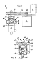
- a head assembly (10) is mounted on a support (12), and comprises a head (14) which comprises a magnet body (16) in which a solenoid (18) is located.
- a central bore of cross-section is provided in the head (14), and is in the form of an upper relatively narrow section, which is extended into an area of relatively large cross-section, before terminating in a relatively short, relatively narrow section at the lower part of the head.
- a photo cell (20) is located within the relatively large section of the bore.
- a spindle (22) of matching cross section with the bore is located within the upper, relatively narrow section, and extends, with its own relatively large extended portion, into the upper part of the relatively large section.
- the head (14) is secured to the spindle (22) which is mounted for rotation about a vertical axis.
- An air or vacuum connection (24) is provided in the head (14) above the solenoid (18) and communicates with the central bore.
- a stepping motor (26) is mounted on the support (12), and connected through the support (12) to a first belt drive wheel (28).
- the first belt drive wheel (28) is connected via a toothed belt (30) to drive a second wheel (32).
- This second wheel (32) is adapted for driving engagement with the spindle (22) of the head (14).
- a switch (not shown) is provided to control the position of the spindle (22).
- a tool holder (40) comprises a magnetic body (42).
- the tool holder (40) is provided with a central bore (44) in which a glass plate (46) is located.
- a tool (48) is located for vertical movement within the tool holder (40), and is guided by grooved bearings (50,52,54).
- the tool (48) is provided with a central bore (56) in which a second glass plate (58) is located.
- An air or vacuum connection (60) is provided in the side wall of the tool holder (40), close to its upper surface (62).
- Precise location of the tool holder (40) on the head assembly (10) is achieved by means of a three-point location system.
- Three spheres (64) are mounted, equiangularly spaced, in the upper surface (62) of the tool holder (40), in recesses (66) machined close to the outer edge of the upper surface.
- Three matching location points are provided on the lower surface of the head (14), spaced to mate with the spheres (64) when the tool holder (40) is received on the head (14).
- the first of these three location points is a concave surface, which determines the x-y position of the tool holder (40) relative to the head (14); the second is a flat surface which determines the height of the tool holder relative to the head and the third is a triangular prism which determines the angular rotation of the tool holder relative to the head.
- the head assembly (10) is driven to a tool bank, which has itself been indexed to locate a selected tool holder (40) at the pick-up station.
- the head (14) picks up the tool holder (40) from the tool bank by means of the solenoid (28).
- a seal between the head (14) and tool holder (40) is provided by an O-ring (68) provided on the upper surface (62) of the tool holder (40). Precise orientation and location of the tool holder is ensured by the three-point system comprising the spheres (64) and matching location points.
- the head assembly including the tool holder, is then driven to the die eject station (104) of the hybrid die bonder where it is supplied with a semiconductor die by a die eject system as described and claimed in our co-pending GB Patent Application No. (F.15094) of even date herewith.
- the die is held onto the tool by suction, the tool being evacuated by means of the air-vacuum connection (60).
- the complete head assembly is then driven to a mounting station where the die is bonded to a substrate.
- the photo cell (20) forms part of a light path control system where illumination is carried out through the glass plates (46,58) to ascertain whether or not a die is held on the tool (48).
- the tool holder is then rotated if necessary, by means of the stepping motor (26) and associated toothed belt (30).
- the die is then appropriately mounted and the head assembly either returned to the die eject station, to pick up a further similar die, or to the tool bank for tool exchange.
Landscapes
- Die Bonding (AREA)
- Auxiliary Devices For Machine Tools (AREA)
- Details Of Connecting Devices For Male And Female Coupling (AREA)
- Perforating, Stamping-Out Or Severing By Means Other Than Cutting (AREA)
- Wire Bonding (AREA)
- Automatic Tool Replacement In Machine Tools (AREA)
- Container, Conveyance, Adherence, Positioning, Of Wafer (AREA)
Applications Claiming Priority (2)
| Application Number | Priority Date | Filing Date | Title |
|---|---|---|---|
| GB909006037A GB9006037D0 (en) | 1990-03-16 | 1990-03-16 | Tool exchange system for hybrid die bonder |
| GB9006037 | 1990-03-16 |
Publications (2)
| Publication Number | Publication Date |
|---|---|
| EP0447087A1 true EP0447087A1 (fr) | 1991-09-18 |
| EP0447087B1 EP0447087B1 (fr) | 1996-06-12 |
Family
ID=10672785
Family Applications (1)
| Application Number | Title | Priority Date | Filing Date |
|---|---|---|---|
| EP91301769A Expired - Lifetime EP0447087B1 (fr) | 1990-03-16 | 1991-03-04 | Système d'échange d'outil pour connecteur de puce hybride |
Country Status (6)
| Country | Link |
|---|---|
| US (1) | US5150530A (fr) |
| EP (1) | EP0447087B1 (fr) |
| JP (1) | JPH0774190A (fr) |
| AT (1) | ATE139407T1 (fr) |
| DE (1) | DE69120111T2 (fr) |
| GB (1) | GB9006037D0 (fr) |
Cited By (1)
| Publication number | Priority date | Publication date | Assignee | Title |
|---|---|---|---|---|
| US7156602B2 (en) | 2001-11-08 | 2007-01-02 | F & K Delvotec Bondtechnick Gmbh | Mechanism for exchanging chip-carrier plates for use in a hybrid chip-bonding machine |
Families Citing this family (2)
| Publication number | Priority date | Publication date | Assignee | Title |
|---|---|---|---|---|
| CH709629B1 (de) * | 2000-10-06 | 2015-11-30 | Chemspeed Technologies Ag | Vorrichtung mit einem Werkzeughalter, einem Werkzeug und einer Waage. |
| WO2009081357A2 (fr) * | 2007-12-19 | 2009-07-02 | Nxp B.V. | Opération de rectification d'outil par bras-transfert |
Citations (5)
| Publication number | Priority date | Publication date | Assignee | Title |
|---|---|---|---|---|
| US4526646A (en) * | 1983-03-03 | 1985-07-02 | Shinkawa Ltd. | Inner lead bonder |
| EP0154552A2 (fr) * | 1984-03-08 | 1985-09-11 | Dynapert Precima Limited | Tête pour ramasser et méthode pour orienter des composants électriques |
| JPS61201431A (ja) * | 1985-03-04 | 1986-09-06 | Tokyo Sokuhan Kk | 自動ダイボンダ− |
| US4795518A (en) * | 1984-02-17 | 1989-01-03 | Burr-Brown Corporation | Method using a multiple device vacuum chuck for an automatic microelectronic bonding apparatus |
| JPH01227442A (ja) * | 1988-03-08 | 1989-09-11 | Matsushita Electron Corp | 半導体ダイボンディング方法 |
Family Cites Families (3)
| Publication number | Priority date | Publication date | Assignee | Title |
|---|---|---|---|---|
| US2976613A (en) * | 1958-01-13 | 1961-03-28 | Voss Engineering Company | Releasable stylus holder for duplicator or tracer mechanism |
| FR2469982A1 (fr) * | 1979-11-26 | 1981-05-29 | Mecalix | Dispositif de positionnement relatif de deux pieces |
| US4390172A (en) * | 1980-11-28 | 1983-06-28 | Presco, Inc. | Precise quick-release positioning mechanism |
-
1990
- 1990-03-16 GB GB909006037A patent/GB9006037D0/en active Pending
-
1991
- 1991-02-27 US US07/661,888 patent/US5150530A/en not_active Expired - Lifetime
- 1991-03-04 DE DE69120111T patent/DE69120111T2/de not_active Expired - Fee Related
- 1991-03-04 EP EP91301769A patent/EP0447087B1/fr not_active Expired - Lifetime
- 1991-03-04 AT AT91301769T patent/ATE139407T1/de not_active IP Right Cessation
- 1991-03-13 JP JP4834691A patent/JPH0774190A/ja active Pending
Patent Citations (5)
| Publication number | Priority date | Publication date | Assignee | Title |
|---|---|---|---|---|
| US4526646A (en) * | 1983-03-03 | 1985-07-02 | Shinkawa Ltd. | Inner lead bonder |
| US4795518A (en) * | 1984-02-17 | 1989-01-03 | Burr-Brown Corporation | Method using a multiple device vacuum chuck for an automatic microelectronic bonding apparatus |
| EP0154552A2 (fr) * | 1984-03-08 | 1985-09-11 | Dynapert Precima Limited | Tête pour ramasser et méthode pour orienter des composants électriques |
| JPS61201431A (ja) * | 1985-03-04 | 1986-09-06 | Tokyo Sokuhan Kk | 自動ダイボンダ− |
| JPH01227442A (ja) * | 1988-03-08 | 1989-09-11 | Matsushita Electron Corp | 半導体ダイボンディング方法 |
Cited By (1)
| Publication number | Priority date | Publication date | Assignee | Title |
|---|---|---|---|---|
| US7156602B2 (en) | 2001-11-08 | 2007-01-02 | F & K Delvotec Bondtechnick Gmbh | Mechanism for exchanging chip-carrier plates for use in a hybrid chip-bonding machine |
Also Published As
| Publication number | Publication date |
|---|---|
| DE69120111T2 (de) | 1997-02-06 |
| GB9006037D0 (en) | 1990-05-09 |
| DE69120111D1 (de) | 1996-07-18 |
| ATE139407T1 (de) | 1996-06-15 |
| JPH0774190A (ja) | 1995-03-17 |
| US5150530A (en) | 1992-09-29 |
| EP0447087B1 (fr) | 1996-06-12 |
Similar Documents
| Publication | Publication Date | Title |
|---|---|---|
| EP0324002B1 (fr) | Tete rotative d'insertion par detection de vide pour machine a connecter des des | |
| JPH0627193A (ja) | 自動テストハンドラー用ピック・プレース装置 | |
| US8021509B2 (en) | Method for affixing adhesive tape to semiconductor wafer, and apparatus using the same | |
| WO2008008411A2 (fr) | Trieuse de moule robotique dotée d'un système d'inspection optique | |
| US7156602B2 (en) | Mechanism for exchanging chip-carrier plates for use in a hybrid chip-bonding machine | |
| KR100701809B1 (ko) | 전자 디바이스 처리 시스템 | |
| CN112295946A (zh) | 芯片自动分选系统 | |
| EP0447083B1 (fr) | Système d'éjection de cube pour connecteur de cube | |
| US5799858A (en) | Die bonding device | |
| JPH10270532A (ja) | チップの供給装置 | |
| EP0447087B1 (fr) | Système d'échange d'outil pour connecteur de puce hybride | |
| CN113307025B (zh) | 基于cob自动组装的料件拾取装置 | |
| EP0306021B1 (fr) | Dispositif de montage de puces | |
| EP0447082B1 (fr) | Système de distribution de cube pour connecteur de cube | |
| US20220208573A1 (en) | Tape mounter | |
| JPH0992664A (ja) | チップの搭載装置 | |
| JP3064781B2 (ja) | 電子部品保持装置 | |
| US5018938A (en) | Method and apparatus for separating chips | |
| US5203659A (en) | Die presentation system for die bonder | |
| JPS5897844A (ja) | ダイ詰め換え装置 | |
| JPS61109635A (ja) | 組立装置 | |
| CN121463846A (zh) | 一种模块自动贴片线 | |
| JPS6177399A (ja) | チツプ部品の自動装着機 | |
| CN119233620A (zh) | 借助平面料箱的垂直的精确定位,用于将元件从平面料箱输送给装配过程的方法及装置 | |
| KR0117628Y1 (ko) | 반도체 제조장비의 매거진 구동장치 |
Legal Events
| Date | Code | Title | Description |
|---|---|---|---|
| PUAI | Public reference made under article 153(3) epc to a published international application that has entered the european phase |
Free format text: ORIGINAL CODE: 0009012 |
|
| AK | Designated contracting states |
Kind code of ref document: A1 Designated state(s): AT CH DE ES FR GB IT LI NL SE |
|
| 17P | Request for examination filed |
Effective date: 19911223 |
|
| RAP1 | Party data changed (applicant data changed or rights of an application transferred) |
Owner name: F & K DELVOTEC BONDTECHNIK GMBH |
|
| 17Q | First examination report despatched |
Effective date: 19940901 |
|
| GRAH | Despatch of communication of intention to grant a patent |
Free format text: ORIGINAL CODE: EPIDOS IGRA |
|
| GRAA | (expected) grant |
Free format text: ORIGINAL CODE: 0009210 |
|
| AK | Designated contracting states |
Kind code of ref document: B1 Designated state(s): AT CH DE ES FR GB IT LI NL SE |
|
| PG25 | Lapsed in a contracting state [announced via postgrant information from national office to epo] |
Ref country code: IT Free format text: LAPSE BECAUSE OF FAILURE TO SUBMIT A TRANSLATION OF THE DESCRIPTION OR TO PAY THE FEE WITHIN THE PRE;WARNING: LAPSES OF ITALIAN PATENTS WITH EFFECTIVE DATE BEFORE 2007 MAY HAVE OCCURRED AT ANY TIME BEFORE 2007. THE CORRECT EFFECTIVE DATE MAY BE DIFFERENT FROM THE ONE RECORDED.SCRIBED TIME-LIMIT Effective date: 19960612 Ref country code: AT Effective date: 19960612 Ref country code: CH Effective date: 19960612 Ref country code: LI Effective date: 19960612 Ref country code: FR Effective date: 19960612 Ref country code: ES Free format text: THE PATENT HAS BEEN ANNULLED BY A DECISION OF A NATIONAL AUTHORITY Effective date: 19960612 Ref country code: NL Free format text: LAPSE BECAUSE OF FAILURE TO SUBMIT A TRANSLATION OF THE DESCRIPTION OR TO PAY THE FEE WITHIN THE PRESCRIBED TIME-LIMIT Effective date: 19960612 |
|
| REF | Corresponds to: |
Ref document number: 139407 Country of ref document: AT Date of ref document: 19960615 Kind code of ref document: T |
|
| REF | Corresponds to: |
Ref document number: 69120111 Country of ref document: DE Date of ref document: 19960718 |
|
| PG25 | Lapsed in a contracting state [announced via postgrant information from national office to epo] |
Ref country code: SE Effective date: 19960912 |
|
| NLV1 | Nl: lapsed or annulled due to failure to fulfill the requirements of art. 29p and 29m of the patents act | ||
| EN | Fr: translation not filed | ||
| REG | Reference to a national code |
Ref country code: CH Ref legal event code: PL |
|
| PG25 | Lapsed in a contracting state [announced via postgrant information from national office to epo] |
Ref country code: GB Effective date: 19970304 |
|
| PLBE | No opposition filed within time limit |
Free format text: ORIGINAL CODE: 0009261 |
|
| STAA | Information on the status of an ep patent application or granted ep patent |
Free format text: STATUS: NO OPPOSITION FILED WITHIN TIME LIMIT |
|
| 26N | No opposition filed | ||
| GBPC | Gb: european patent ceased through non-payment of renewal fee |
Effective date: 19970304 |
|
| PGFP | Annual fee paid to national office [announced via postgrant information from national office to epo] |
Ref country code: DE Payment date: 20080519 Year of fee payment: 18 |
|
| PG25 | Lapsed in a contracting state [announced via postgrant information from national office to epo] |
Ref country code: DE Free format text: LAPSE BECAUSE OF NON-PAYMENT OF DUE FEES Effective date: 20091001 |