EP0447370A1 - Verfahren und Vorrichtung zur Verbindung eines Kolbens mit seiner Kolbenstange - Google Patents
Verfahren und Vorrichtung zur Verbindung eines Kolbens mit seiner Kolbenstange Download PDFInfo
- Publication number
- EP0447370A1 EP0447370A1 EP91830051A EP91830051A EP0447370A1 EP 0447370 A1 EP0447370 A1 EP 0447370A1 EP 91830051 A EP91830051 A EP 91830051A EP 91830051 A EP91830051 A EP 91830051A EP 0447370 A1 EP0447370 A1 EP 0447370A1
- Authority
- EP
- European Patent Office
- Prior art keywords
- piston
- rod
- neck
- axial
- coupling
- Prior art date
- Legal status (The legal status is an assumption and is not a legal conclusion. Google has not performed a legal analysis and makes no representation as to the accuracy of the status listed.)
- Granted
Links
- 238000000034 method Methods 0.000 title claims abstract description 12
- 230000008878 coupling Effects 0.000 claims abstract description 11
- 238000010168 coupling process Methods 0.000 claims abstract description 11
- 238000005859 coupling reaction Methods 0.000 claims abstract description 11
- 230000002093 peripheral effect Effects 0.000 claims abstract description 5
- 238000005452 bending Methods 0.000 claims description 5
- 238000007789 sealing Methods 0.000 description 1
Images
Classifications
-
- F—MECHANICAL ENGINEERING; LIGHTING; HEATING; WEAPONS; BLASTING
- F16—ENGINEERING ELEMENTS AND UNITS; GENERAL MEASURES FOR PRODUCING AND MAINTAINING EFFECTIVE FUNCTIONING OF MACHINES OR INSTALLATIONS; THERMAL INSULATION IN GENERAL
- F16J—PISTONS; CYLINDERS; SEALINGS
- F16J1/00—Pistons; Trunk pistons; Plungers
- F16J1/10—Connection to driving members
- F16J1/12—Connection to driving members with piston-rods, e.g. rigid connections
Definitions
- the present invention relates to a method and equipment for fixing or closing a piston body onto a piston rod, and in particular relates to servodrive pistons.
- a method of closing a piston body around a rod which consists of cold heading or bending a neck protruding from a head of the piston into a peripheral groove on the rod is also known. This is carried out by a single closing action on the piston which is opposite to a back drafted stationary support so as to deviate and cold head said neck in the corresponding groove. Even in this case, the closure obtained does not exclude the possibility of axial movements when under pressure.
- the object of the present invention is to solve the problem of the closure of a piston on a rod and to obviate the above mentioned inconveniences so as to eliminate any movement of the piston on the rod, even when under pressure.
- Another object of the invention is to propose a coupling between a piston and a rod with an efficient axial seal which is both mechanical and hydraulic.
- Said method is thus carried out in two consecutive stages and with a stronger thrust in the second stage than the one in the first.
- the final thrust applied to the piston is necessary so as to eliminate the coupling movements and assure both a mechanical and hydraulic axial seal of the piston on the rod which is obtained by the cold heading or bending of the neck into the groove.
- the equipment for using the above mentioned method comprises a back drafted fixed support for the cold heading and bending of the neck, which is integral with the piston, into the groove of the rod and is charcterized in that it also comprises two thrust members which coaxially extend into each other, which are operated by respective actuators of different power and which are designed to engage on the rod and on the piston in subsequent stages.
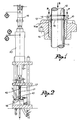
- a piston (10) formed of a separate body is designed to be fixed onto a piston rod (11) between two grooves (12, 13).
- a stop ring (14) which rests against a surface of the piston is set in one of the grooves whilst a neck (15) which is integral with the other surface of the piston is cold headed or bent into the other groove.
- a support block (16) a first thrust member (17) moved by a respective hydraulic or pneumatic cylinder (18) and a second thrust member moved by a respective hydraulic or pneumatic cylinder (20).
- the support block (16) has a counter-shape (16a) so as to cause the cold heading or bending of the neck (15) of the piston (10) into the corresponding groove (13) of the rod (11).
- the first member (17) coaxially extends into the second member (19) which is tubular, and both members (17, 19) are aligned on the axis of the support block (16).
- the cylinders (18, 20) which control the thrust members (17, 19) do not have the same power and are however necessary until the first cylinder develops a force (S) on the member (17) which is weaker than the thrust (P) developed by the second cylinder on the other member (19).
- the piston and rod (10, 11) together are placed onto the support block (16) with the neck (15) of the piston turned towards said block.
- the piston is axially held on the opposite side to the ring (14) engaged in the groove (12) of the rod (Fig. 1).
- an axial force (S) is applied to the rod (11) by the first member (17) for an elastic cross-loading-of the coupling through an initial cold-heading of the neck (15) into the groove (13).
- a stronger force (P) is then applied to the piston (10) by the second member (19) whilst maintaining the axial thrust (S) on the rod (11).
Landscapes
- Engineering & Computer Science (AREA)
- General Engineering & Computer Science (AREA)
- Chemical & Material Sciences (AREA)
- Combustion & Propulsion (AREA)
- Mechanical Engineering (AREA)
- Pistons, Piston Rings, And Cylinders (AREA)
- Actuator (AREA)
- Telephone Function (AREA)
Applications Claiming Priority (2)
| Application Number | Priority Date | Filing Date | Title |
|---|---|---|---|
| IT513490 | 1990-03-15 | ||
| IT5134A IT1238566B (it) | 1990-03-15 | 1990-03-15 | Metodo ed attrezzatura per il fissaggio di un pistone su uno stelo |
Publications (2)
| Publication Number | Publication Date |
|---|---|
| EP0447370A1 true EP0447370A1 (de) | 1991-09-18 |
| EP0447370B1 EP0447370B1 (de) | 1994-08-10 |
Family
ID=11118153
Family Applications (1)
| Application Number | Title | Priority Date | Filing Date |
|---|---|---|---|
| EP91830051A Expired - Lifetime EP0447370B1 (de) | 1990-03-15 | 1991-02-18 | Verfahren und Vorrichtung zur Verbindung eines Kolbens mit seiner Kolbenstange |
Country Status (4)
| Country | Link |
|---|---|
| EP (1) | EP0447370B1 (de) |
| DE (1) | DE69103300T2 (de) |
| ES (1) | ES2059098T3 (de) |
| IT (1) | IT1238566B (de) |
Citations (4)
| Publication number | Priority date | Publication date | Assignee | Title |
|---|---|---|---|---|
| GB1117777A (en) * | 1965-09-17 | 1968-06-26 | Martonair Ltd | Forming an annular abutment on a shaft |
| EP0033251A2 (de) * | 1980-01-25 | 1981-08-05 | S.A.M.M.- Société d'Applications des Machines Motrices | In einem Zylinder gleitende Kolben- und Kolbenstangeneinheit |
| FR2533983A1 (fr) * | 1982-10-04 | 1984-04-06 | Sin Tech Ltd | Liaison entre un premier element et un alesage forme dans un second element et procede pour sa realisation |
| EP0126698A1 (de) * | 1983-04-20 | 1984-11-28 | Cegedur Societe De Transformation De L'aluminium Pechiney | Montierungsverfahren für ein ringförmiges Element mit einem Rohr aus Aluminium oder einer Aluminiumzusammensetzung |
-
1990
- 1990-03-15 IT IT5134A patent/IT1238566B/it active IP Right Grant
-
1991
- 1991-02-18 ES ES91830051T patent/ES2059098T3/es not_active Expired - Lifetime
- 1991-02-18 DE DE69103300T patent/DE69103300T2/de not_active Expired - Fee Related
- 1991-02-18 EP EP91830051A patent/EP0447370B1/de not_active Expired - Lifetime
Patent Citations (4)
| Publication number | Priority date | Publication date | Assignee | Title |
|---|---|---|---|---|
| GB1117777A (en) * | 1965-09-17 | 1968-06-26 | Martonair Ltd | Forming an annular abutment on a shaft |
| EP0033251A2 (de) * | 1980-01-25 | 1981-08-05 | S.A.M.M.- Société d'Applications des Machines Motrices | In einem Zylinder gleitende Kolben- und Kolbenstangeneinheit |
| FR2533983A1 (fr) * | 1982-10-04 | 1984-04-06 | Sin Tech Ltd | Liaison entre un premier element et un alesage forme dans un second element et procede pour sa realisation |
| EP0126698A1 (de) * | 1983-04-20 | 1984-11-28 | Cegedur Societe De Transformation De L'aluminium Pechiney | Montierungsverfahren für ein ringförmiges Element mit einem Rohr aus Aluminium oder einer Aluminiumzusammensetzung |
Also Published As
| Publication number | Publication date |
|---|---|
| DE69103300D1 (de) | 1994-09-15 |
| IT9005134A0 (it) | 1990-03-15 |
| DE69103300T2 (de) | 1995-02-16 |
| IT1238566B (it) | 1993-08-18 |
| ES2059098T3 (es) | 1994-11-01 |
| EP0447370B1 (de) | 1994-08-10 |
| IT9005134A1 (it) | 1991-09-15 |
Similar Documents
| Publication | Publication Date | Title |
|---|---|---|
| US4960039A (en) | Cylinder with sleeve compacter seals for high pressure pumps | |
| EP0344785A2 (de) | Gasfeder mit mehreren hintereinander angeordneten Druckräumen | |
| GB2109061A (en) | Annular seal | |
| SE8300756L (sv) | Tryckfluidumpaverkat manoverdon for stegvis ventilreglering | |
| EP0447370A1 (de) | Verfahren und Vorrichtung zur Verbindung eines Kolbens mit seiner Kolbenstange | |
| RU2126336C1 (ru) | Главный гидравлический цилиндр | |
| KR940010372B1 (ko) | 밀봉링 | |
| US2170574A (en) | Hydraulic seal | |
| JPH106096A (ja) | 液圧によるプレスシャットハイト制御 | |
| NO179299C (no) | Gassdrevet ventil-aktuator | |
| GB1061175A (en) | Fluid pressure operated multi-position ram | |
| US3815481A (en) | Power cylinder with piston return by own vacuum force | |
| EP1211375A3 (de) | Brems- und Dämpfungselement für bewegliche Möbelteile | |
| JPH07507519A (ja) | マスターシリンダー | |
| GB2082246A (en) | Ball and socket joints | |
| EP0822343A3 (de) | Stellungsregler sowie Regelventil mit einem derartigen Stellungsregler | |
| JPS61262205A (ja) | 湾曲自在なアクチユエ−タ | |
| CN209959617U (zh) | 一种等速等推力二级液压缸 | |
| RU2170859C1 (ru) | Гидроцилиндр плунжерный | |
| FR2288895A1 (fr) | Verin a mecanisme detecteur de fins de course incorpore | |
| RU1838704C (ru) | Вакуумный клапан с электромагнитным приводом и гидравлическим демпфером | |
| DE2318499A1 (de) | Bremssteuereinrichtung, insbesondere fuer schienenfahrzeuge | |
| CN113669326B (zh) | 一种应用于液压驱动腿足机器人的双活塞杆液压伺服油缸 | |
| DE59203094D1 (de) | Zweistufiges Ventil. | |
| GB1517561A (en) | Fluid pressure operated actuators |
Legal Events
| Date | Code | Title | Description |
|---|---|---|---|
| PUAI | Public reference made under article 153(3) epc to a published international application that has entered the european phase |
Free format text: ORIGINAL CODE: 0009012 |
|
| AK | Designated contracting states |
Kind code of ref document: A1 Designated state(s): DE ES FR GB IT SE |
|
| 17P | Request for examination filed |
Effective date: 19920227 |
|
| 17Q | First examination report despatched |
Effective date: 19931019 |
|
| GRAA | (expected) grant |
Free format text: ORIGINAL CODE: 0009210 |
|
| AK | Designated contracting states |
Kind code of ref document: B1 Designated state(s): DE ES FR GB IT SE |
|
| REF | Corresponds to: |
Ref document number: 69103300 Country of ref document: DE Date of ref document: 19940915 |
|
| ITF | It: translation for a ep patent filed | ||
| ET | Fr: translation filed | ||
| REG | Reference to a national code |
Ref country code: ES Ref legal event code: FG2A Ref document number: 2059098 Country of ref document: ES Kind code of ref document: T3 |
|
| PG25 | Lapsed in a contracting state [announced via postgrant information from national office to epo] |
Ref country code: SE Effective date: 19941110 |
|
| PLBE | No opposition filed within time limit |
Free format text: ORIGINAL CODE: 0009261 |
|
| STAA | Information on the status of an ep patent application or granted ep patent |
Free format text: STATUS: NO OPPOSITION FILED WITHIN TIME LIMIT |
|
| 26N | No opposition filed | ||
| REG | Reference to a national code |
Ref country code: GB Ref legal event code: IF02 |
|
| PGFP | Annual fee paid to national office [announced via postgrant information from national office to epo] |
Ref country code: GB Payment date: 20050110 Year of fee payment: 15 |
|
| PGFP | Annual fee paid to national office [announced via postgrant information from national office to epo] |
Ref country code: FR Payment date: 20050202 Year of fee payment: 15 |
|
| PGFP | Annual fee paid to national office [announced via postgrant information from national office to epo] |
Ref country code: ES Payment date: 20050217 Year of fee payment: 15 |
|
| PG25 | Lapsed in a contracting state [announced via postgrant information from national office to epo] |
Ref country code: GB Free format text: LAPSE BECAUSE OF NON-PAYMENT OF DUE FEES Effective date: 20060218 |
|
| PG25 | Lapsed in a contracting state [announced via postgrant information from national office to epo] |
Ref country code: ES Free format text: LAPSE BECAUSE OF NON-PAYMENT OF DUE FEES Effective date: 20060220 |
|
| PGFP | Annual fee paid to national office [announced via postgrant information from national office to epo] |
Ref country code: IT Payment date: 20060228 Year of fee payment: 16 |
|
| GBPC | Gb: european patent ceased through non-payment of renewal fee |
Effective date: 20060218 |
|
| REG | Reference to a national code |
Ref country code: FR Ref legal event code: ST Effective date: 20061031 |
|
| REG | Reference to a national code |
Ref country code: ES Ref legal event code: FD2A Effective date: 20060220 |
|
| PG25 | Lapsed in a contracting state [announced via postgrant information from national office to epo] |
Ref country code: FR Free format text: LAPSE BECAUSE OF NON-PAYMENT OF DUE FEES Effective date: 20060228 |
|
| PGFP | Annual fee paid to national office [announced via postgrant information from national office to epo] |
Ref country code: DE Payment date: 20080229 Year of fee payment: 18 |
|
| PG25 | Lapsed in a contracting state [announced via postgrant information from national office to epo] |
Ref country code: IT Free format text: LAPSE BECAUSE OF NON-PAYMENT OF DUE FEES Effective date: 20070218 |
|
| PG25 | Lapsed in a contracting state [announced via postgrant information from national office to epo] |
Ref country code: DE Free format text: LAPSE BECAUSE OF NON-PAYMENT OF DUE FEES Effective date: 20090901 |