EP0447475B1 - Agencement optoelectronique de detection - Google Patents
Agencement optoelectronique de detection Download PDFInfo
- Publication number
- EP0447475B1 EP0447475B1 EP90900852A EP90900852A EP0447475B1 EP 0447475 B1 EP0447475 B1 EP 0447475B1 EP 90900852 A EP90900852 A EP 90900852A EP 90900852 A EP90900852 A EP 90900852A EP 0447475 B1 EP0447475 B1 EP 0447475B1
- Authority
- EP
- European Patent Office
- Prior art keywords
- thread
- sensing device
- sensing
- image
- region
- Prior art date
- Legal status (The legal status is an assumption and is not a legal conclusion. Google has not performed a legal analysis and makes no representation as to the accuracy of the status listed.)
- Expired - Lifetime
Links
- 230000005693 optoelectronics Effects 0.000 title claims abstract description 11
- 239000011159 matrix material Substances 0.000 claims description 12
- 238000003384 imaging method Methods 0.000 claims description 11
- 238000004804 winding Methods 0.000 claims description 10
- 230000003287 optical effect Effects 0.000 claims description 6
- 230000001427 coherent effect Effects 0.000 claims description 3
- 238000012634 optical imaging Methods 0.000 claims 7
- 230000004807 localization Effects 0.000 claims 1
- 230000005499 meniscus Effects 0.000 claims 1
- 230000009467 reduction Effects 0.000 description 3
- 239000004753 textile Substances 0.000 description 3
- 238000009941 weaving Methods 0.000 description 3
- 230000008859 change Effects 0.000 description 2
- 238000010586 diagram Methods 0.000 description 2
- 238000011156 evaluation Methods 0.000 description 2
- 239000004744 fabric Substances 0.000 description 2
- 238000000034 method Methods 0.000 description 2
- 238000012544 monitoring process Methods 0.000 description 2
- 238000011144 upstream manufacturing Methods 0.000 description 2
- 230000004075 alteration Effects 0.000 description 1
- 230000003321 amplification Effects 0.000 description 1
- 230000008901 benefit Effects 0.000 description 1
- 238000011109 contamination Methods 0.000 description 1
- 230000007547 defect Effects 0.000 description 1
- 239000000835 fiber Substances 0.000 description 1
- 230000007274 generation of a signal involved in cell-cell signaling Effects 0.000 description 1
- 230000003760 hair shine Effects 0.000 description 1
- 230000012447 hatching Effects 0.000 description 1
- 238000005286 illumination Methods 0.000 description 1
- 238000013507 mapping Methods 0.000 description 1
- 239000000463 material Substances 0.000 description 1
- 238000003199 nucleic acid amplification method Methods 0.000 description 1
- 238000012545 processing Methods 0.000 description 1
- 238000010079 rubber tapping Methods 0.000 description 1
- 239000000523 sample Substances 0.000 description 1
- 230000001629 suppression Effects 0.000 description 1
Images
Classifications
-
- G—PHYSICS
- G01—MEASURING; TESTING
- G01N—INVESTIGATING OR ANALYSING MATERIALS BY DETERMINING THEIR CHEMICAL OR PHYSICAL PROPERTIES
- G01N21/00—Investigating or analysing materials by the use of optical means, i.e. using sub-millimetre waves, infrared, visible or ultraviolet light
- G01N21/84—Systems specially adapted for particular applications
-
- D—TEXTILES; PAPER
- D03—WEAVING
- D03D—WOVEN FABRICS; METHODS OF WEAVING; LOOMS
- D03D47/00—Looms in which bulk supply of weft does not pass through shed, e.g. shuttleless looms, gripper shuttle looms, dummy shuttle looms
- D03D47/34—Handling the weft between bulk storage and weft-inserting means
- D03D47/36—Measuring and cutting the weft
- D03D47/361—Drum-type weft feeding devices
- D03D47/367—Monitoring yarn quantity on the drum
-
- B—PERFORMING OPERATIONS; TRANSPORTING
- B65—CONVEYING; PACKING; STORING; HANDLING THIN OR FILAMENTARY MATERIAL
- B65H—HANDLING THIN OR FILAMENTARY MATERIAL, e.g. SHEETS, WEBS, CABLES
- B65H63/00—Warning or safety devices, e.g. automatic fault detectors, stop-motions ; Quality control of the package
- B65H63/02—Warning or safety devices, e.g. automatic fault detectors, stop-motions ; Quality control of the package responsive to reduction in material tension, failure of supply, or breakage, of material
- B65H63/024—Warning or safety devices, e.g. automatic fault detectors, stop-motions ; Quality control of the package responsive to reduction in material tension, failure of supply, or breakage, of material responsive to breakage of materials
- B65H63/028—Warning or safety devices, e.g. automatic fault detectors, stop-motions ; Quality control of the package responsive to reduction in material tension, failure of supply, or breakage, of material responsive to breakage of materials characterised by the detecting or sensing element
- B65H63/032—Warning or safety devices, e.g. automatic fault detectors, stop-motions ; Quality control of the package responsive to reduction in material tension, failure of supply, or breakage, of material responsive to breakage of materials characterised by the detecting or sensing element electrical or pneumatic
- B65H63/0321—Warning or safety devices, e.g. automatic fault detectors, stop-motions ; Quality control of the package responsive to reduction in material tension, failure of supply, or breakage, of material responsive to breakage of materials characterised by the detecting or sensing element electrical or pneumatic using electronic actuators
- B65H63/0324—Warning or safety devices, e.g. automatic fault detectors, stop-motions ; Quality control of the package responsive to reduction in material tension, failure of supply, or breakage, of material responsive to breakage of materials characterised by the detecting or sensing element electrical or pneumatic using electronic actuators using photo-electric sensing means, i.e. the defect signal is a variation of light energy
-
- D—TEXTILES; PAPER
- D03—WEAVING
- D03D—WOVEN FABRICS; METHODS OF WEAVING; LOOMS
- D03D51/00—Driving, starting, or stopping arrangements; Automatic stop motions
- D03D51/18—Automatic stop motions
- D03D51/34—Weft stop motions
-
- G—PHYSICS
- G01—MEASURING; TESTING
- G01B—MEASURING LENGTH, THICKNESS OR SIMILAR LINEAR DIMENSIONS; MEASURING ANGLES; MEASURING AREAS; MEASURING IRREGULARITIES OF SURFACES OR CONTOURS
- G01B11/00—Measuring arrangements characterised by the use of optical techniques
-
- G—PHYSICS
- G01—MEASURING; TESTING
- G01P—MEASURING LINEAR OR ANGULAR SPEED, ACCELERATION, DECELERATION, OR SHOCK; INDICATING PRESENCE, ABSENCE, OR DIRECTION, OF MOVEMENT
- G01P13/00—Indicating or recording presence, absence, or direction, of movement
-
- G—PHYSICS
- G01—MEASURING; TESTING
- G01P—MEASURING LINEAR OR ANGULAR SPEED, ACCELERATION, DECELERATION, OR SHOCK; INDICATING PRESENCE, ABSENCE, OR DIRECTION, OF MOVEMENT
- G01P3/00—Measuring linear or angular speed; Measuring differences of linear or angular speeds
- G01P3/36—Devices characterised by the use of optical means, e.g. using infrared, visible, or ultraviolet light
- G01P3/38—Devices characterised by the use of optical means, e.g. using infrared, visible, or ultraviolet light using photographic means
-
- G—PHYSICS
- G01—MEASURING; TESTING
- G01P—MEASURING LINEAR OR ANGULAR SPEED, ACCELERATION, DECELERATION, OR SHOCK; INDICATING PRESENCE, ABSENCE, OR DIRECTION, OF MOVEMENT
- G01P3/00—Measuring linear or angular speed; Measuring differences of linear or angular speeds
- G01P3/64—Devices characterised by the determination of the time taken to traverse a fixed distance
- G01P3/68—Devices characterised by the determination of the time taken to traverse a fixed distance using optical means, i.e. using infrared, visible, or ultraviolet light
-
- B—PERFORMING OPERATIONS; TRANSPORTING
- B65—CONVEYING; PACKING; STORING; HANDLING THIN OR FILAMENTARY MATERIAL
- B65H—HANDLING THIN OR FILAMENTARY MATERIAL, e.g. SHEETS, WEBS, CABLES
- B65H2513/00—Dynamic entities; Timing aspects
- B65H2513/10—Speed
- B65H2513/11—Speed angular
-
- B—PERFORMING OPERATIONS; TRANSPORTING
- B65—CONVEYING; PACKING; STORING; HANDLING THIN OR FILAMENTARY MATERIAL
- B65H—HANDLING THIN OR FILAMENTARY MATERIAL, e.g. SHEETS, WEBS, CABLES
- B65H2701/00—Handled material; Storage means
- B65H2701/30—Handled filamentary material
- B65H2701/31—Textiles threads or artificial strands of filaments
Definitions
- the invention relates to an optoelectronic thread guiding device of the type specified in the preamble of claim 1 and a thread storage and delivery device according to claim 26.
- An apparently previously used optoelectronic thread guiding device for determining the thread passage in an annular gap of a thread storage and delivery device contains a light-emitting diode as the light source and a photodiode or a phototransistor as the receiver.
- a converging lens in front of the receiver surface bundles parallel rays and looks at a cylindrical and infinite sensing area. The focal point of the converging lens is infinite.
- the receiver is set to a threshold. In the event of a predetermined change in the brightness on the receiver surface, the useful signal is generated, the light emitted, for example reflected, by the respective object present in the sensing region being distributed uniformly over the receiver surface.
- the useful signals are very weak.
- the cylindrical sensing region is as deep as the fabric width. Light reflected from a warp thread or from a larger amount of dirt is bundled by a converging lens and distributed evenly on the receiver surface. If there is sufficient illumination, the useful signal is generated.
- an object line for example a bar code
- imaging optics scanned and the information contained in the item line determined.
- EP-A3-0 162 134 flat strips of the fabric are continuously scanned for texture defects in a weaving machine by means of a moving probe. Optics suitable for this purpose are provided on the receiver side. In order to obtain information from each strip, the luminance value is evaluated on a scan line.
- the instantaneous image of a yarn section is recorded and implemented with an image sensor so that the strength, out-of-roundness, twist, twist, protrude Fibers or elongation.
- Either the stationary yarn is examined, or a snapshot is taken when it is moved in the longitudinal direction, or a sequence of pictures is taken and implemented with a stroboscope.
- the information that can be extracted from the image of the existing object is determined, the presence of the object is assumed. However, the object is not imaged in order to derive a useful signal from the passage or the presence or absence of the object.
- the invention has for its object to provide an optoelectronic thread guiding device of a thread storage and delivery device with which strong, clear and interference-free useful signals can be generated.
- the sharp image of the thread generated on the receiver surface is distinctive and high-contrast and differs significantly from the image when the thread is absent. This leads to a strong useful signal during the evaluation, which deviates significantly from the basic signal in the absence of the thread. Since with the imaging optics on the receiver surface fluff in the sensing area, as is inevitable when working with threads in a thread storage and delivery device, give a different image than the thread, which can be taken into account in the evaluation, a distinction can be made between the thread and fluff and the delivery of a "wrong" useful signal can be suppressed. Since the imaging optics ignore fluff in front of or behind the sensing area due to the depth of field setting, "false" useful signals are also avoided.
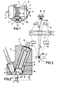
- a thread storage and delivery device 1 is equipped with three different sensing devices F for different functions.
- the device 1 contains a winding element 4 driven by a drive 2, which winds a thread 7 tapering through the drive 2 in turns into a thread supply 8 on a storage surface 3. From this, the thread 7 is drawn around the circumference under a ring 5 (annular gap 9) and drawn off through a thread eyelet 6.
- An optoelectronic sensing device F arranged in the ring 5 detects the passage of the thread 7 with each revolution and generates useful signals which are processed, for example, to calculate the length of the thread being drawn off, its speed or to determine a thread break.
- the optoelectronic sensing device F associated with the winding member 4 determines the proper passage of the thread 7 and the speed of the winding member 4 or the drive 2 without contact. A thread break is also detected if the useful signal expected from the passage of the thread at a certain point in time does not appear.
- This sensing device either monitors the thread 7 emerging from the winding element 4 during its passages (for a thread break upstream or / and for the winding speed or the number of turns) or the area of at least the first thread turn in the supply 8 (for a thread break upstream). In both cases, the sensing device also serves to determine the linear thread movement.
- the third sensing device F is fixed outside of the storage area 3 on a holder and aligned with the thread supply 8. It monitors a bar-shaped sensing area in which the windings are present as an elongated object, possibly interrupted by gaps.
- Light sources 10 illuminate the sensing area so that the sensing device F uses an objective lens with a converging lens 11 to image the object on a sensitive receiver surface 12.
- An image converter 13 generates different useful signals from the image, as will be explained later.
- These three sensing devices F are a selection from a large number of possibilities for using such sensing devices. Basically, these sensing devices can be used for generating useful signals with more precise scanning of one or more threads or thread parts, for textile machines such as weaving machines, for these devices or in the textile machine itself.
- Fig. 2 is a section of the sensing device F in the ring 5.
- the light source L is a photodiode 10, which shines through an oblique channel 14 into the annular gap 9 through which the drawn thread 7 passes transversely. The angle of incidence and angle of emergence are approx. 20 o each.
- a photo element 15, for example a photodiode or a phototransistor is aligned with a receiver surface 16, which lies at the end of a lined tube 7 designed as an aperture, at the other end of which an imaging optics 18, for example a converging lens, is arranged .
- the optical axis 20 of the converging lens is aligned with the receiver surface 16 and the thread.
- a further aperture 19 is, preferably light-lined channel, provided on the other side of the imaging optics 18.
- the annular gap width W is, for example, 5 mm.
- the depth of field of the imaging optics 18 is designed for this, and it considers the sensing area that is also limited in width, for example in the width of the thread 7. The sensing range is therefore visually limited both in depth and at least in width.
- the imaging optics 18 produces a sharp image of the thread on the receiver surface 16, which is evaluated by the photo element 15 to generate a useful signal.
- an objective J representing the imaging optics A produces the image BF 'of the thread 7, represented by an arrow BF representing the object, on the receiver surface 16.
- the focal points F1, F2 on the object and image side of the objective J which here contains at least one biconvex converging lens 11, are each between the objective J and the receiver surface 16 and between the objective J and the annular gap 9.
- the object BF is inverted and with a adjustable enlargement or reduction mapped on the receiver surface 16 and evaluated by the photo element 15 to emit the useful signal.
- the sensing area has a width B and a depth T which corresponds at most to the depth of the annular gap 9.
- the apertures 19, 17 improve the sharpness of the image BF 'and adjust the depth of field in the sensing area.
- the apertures 19, 17 compensate for aberrations by possibly distorting edge areas of the converging lens 11.
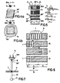
- the sharp image BF ' covers almost the entire receiver area 16. Only the horizontally hatched corners lie outside the edges of the Figure BF '.
- the photo element 15 is designed as an image converter BW or combined with an image converter BW, which evaluates the image within its limits and generates a useful signal S1, for example a digital one.
- the useful signal 1 is only generated if the image converter BW has a certain light intensity within the image the sharp boundaries determines what is indicated by the dense hatching of the small box indicating the receiver surface 16 above FIG. 4A.
- a tuft of lint enters the sensing area, its image BV 'is larger than the image BF'. Because of the greater transparency of the fluff tuft, the image BV 'on the receiver surface 16 has a lower brightness.
- the image converter detects the lower brightness and does not generate a useful signal, but a basic signal S2 or another signal, e.g. a digital 0.
- the image converter BW can be composed of several photo elements in row or matrix form in order to evaluate the image as precisely as possible.
- 5 (a, b) the receiver surface 16, which belongs to the image converter BW, is designed as a flat matrix (here three rows R1, R2, R3) of individual image-sensitive light point elements or pixels 21 which are sequential (e.g. from left to right) right) scanning control circuit (not shown) is connected.
- the image BF'8 of the thread supply 8 is an elongated rectangle, on the two narrow sides of which there are non-illuminated pixels. In the associated sensing area with the width B shown in FIG. 6, A, there are five turns of the thread 7 between with narrow distances. The figure BF'8 is made from this.
- the image converter BW converts the image BF'8 in digitized form for each scanning sequence into a signal chain shown to the right of FIG. 5, a (diagram of voltage over time). There are five clear signals in the signal chain, in front of and behind which there are no clear signals.
- the time t1 represents the beginning of the thread supply 8 in the scanning direction
- the time span tx corresponds to the size of the thread supply or the number of turns
- the time t2 represents the end of the thread supply.
- these signals t1, tx, t2 are representative of the size and position of the supply 8 in the sensing area.
- the thread supply 8, FIG. 6, B is reduced to two turns, namely from the right (take-off) side. 5b, the mapping BF' Ab Struktur is correspondingly smaller. Fewer pixels of the image are hit in the matrix of the image converter BW.
- the signal chain shown to the right of FIG. 5, b contains only two clear signals. That the time tw and the time span tx1 differ from the previously determined t2, tx can be determined by comparison (for example in a microprocessor) both the reduction in the size of the image and the direction of the decrease. Depending on the result, the winding member 4 (FIG. 1) can increase the stock 8 again.
- the drive 2 (FIG. 1) is switched off again.
- the procedure is then such that, by means of the scanning, a continuous drive for the thread winding element 4 is set.
- a reduction or enlargement of the image BF'8 during the scanning, which can no longer be compensated for, means a fault, for example a thread break, which is processed into a fault display or a switch-off signal.
- useful signals which are processed with a microprocessor, can be used in the event of irregularities that are too great or in the absence of a fault signal or switch-off signal.
- the monitoring of the thread supply 8 could also be carried out with the row R of the light point elements 21 (FIGS. 5c and d).
- a flat matrix (FIGS. 5a and b), however, has the advantage of particularly clear and strong signals and avoids problems that could result from problems with the correct alignment of the optical axis of the objective J on the receiver surface 16 or the image converter BW.
- the image BF 'of the thread 7 when moving in successive scanning cycles, leads to a signal chain in which a single signal representing the presence of the image BF' leads to different ones Points in time occurs.
- the time difference dt is evaluated to determine the speed of movement and the direction of movement.
- the correct presence of the thread 7 is also determined because fluff or other foreign bodies cause easily recognizable and therefore distinguishable signals.
- a bundle of coherent light 22 from a laser light source Q is directed through the annular gap 9 onto the receiver surface 16.
- the image BF 'of the thread 7 is sharp enough due to the coherent light 22, so that the image converter BW, even in the form of a flat or row-shaped matrix, is reliably evaluated.
- thread with a diameter of 0.4mm and a light attenuation of 30% Tuft of lint with a diameter of 4mm and a light attenuation of 6%.
- the size of the receiver surface 16 is matched to the diameter of the thread 7, i.e. the image produced by the imaging optics 18 covers the receiver surface 16.
- the known sensing device uses the converging lens to monitor a cylinder with a diameter of 6 mm.
- the sensing area thus has an area of approximately 27 mm 2, the area that the thread occupies within the sensing area is approximately 2.4 mm 2. This results in a modulation of approx. 2.6% for the thread.
- the fluff tuft represents an area of approximately 12mm2 with a modulation of 2.6%. It can be seen from this that the tuft of threads produces the same light modulation as the thread, although its light attenuation is only 1/5 of the light attenuation of the thread.
- the known sensing device generates a false signal in the fluff tuft in the sensing area.
- the sensing area is limited to 0.13mm2, whereby the area of the thread in the sensing area is also 0.13mm2, i.e. the thread fills the sensing area and its image on the receiver surface covers it.
- the light modulation of the thread is 30%.
- a tuft of lint present in the sensing area is scanned for 0.13 mm2, which leads to a light modulation of only 6%. Due to the factor 5 between the scanned objects, the photo element is able to distinguish between the thread and the fluff tuft and to suppress a false signal.
Landscapes
- Physics & Mathematics (AREA)
- General Physics & Mathematics (AREA)
- Engineering & Computer Science (AREA)
- Textile Engineering (AREA)
- Electromagnetism (AREA)
- Power Engineering (AREA)
- Quality & Reliability (AREA)
- Analytical Chemistry (AREA)
- Pathology (AREA)
- Chemical & Material Sciences (AREA)
- Health & Medical Sciences (AREA)
- Biochemistry (AREA)
- General Health & Medical Sciences (AREA)
- Immunology (AREA)
- Life Sciences & Earth Sciences (AREA)
- Treatment Of Fiber Materials (AREA)
- Looms (AREA)
- Investigating Materials By The Use Of Optical Means Adapted For Particular Applications (AREA)
- Forwarding And Storing Of Filamentary Material (AREA)
- Filamentary Materials, Packages, And Safety Devices Therefor (AREA)
- Geophysics And Detection Of Objects (AREA)
- Length Measuring Devices By Optical Means (AREA)
Abstract
Claims (26)
- Agencement optoélectronique (F) de détection de fil, d'un dispositif (1) d'accumulation et d'amenée de fil, pour le fil (7), déplacé dans une zone de détection transversalement à sa direction longitudinale, dont la présence doit être déterminée dans la zone de détection,
comprenant une source lumineuse,
et une surface de réception (16) sensible à la lumière,
qui fait partie au moins d'un élément photosensible (15) engendrant un signal utile lorsque le fil (7) traverse la zone de détection,
et comprenant un système optique disposé entre la source lumineuse (L) et la surface de réception (16)
caractérisé en ce que
le système optique est une optique d'image (A, 18) dont la profondeur de champ limite du côté de la zone de détection une profondeur prédéterminée (T) de la zone de détection et dont la zone d'observation est limitée au moins dans la largeur (B),
qui correspond à peu près à la largeur du fil,
et en ce que la surface de réception (16) est disposée à l'intérieur de la profondeur de champ de l'optique d'image (A, 18). - Agencement de détection de fil selon la revendication 1, caractérisé en ce que l'élément photosensible (15) présente un transformateur de numérisation d'image pour la netteté d'image sur la surface de réception (16).
- Agencement de détection de fil selon la revendication 1, caractérisée en ce que la largeur (B) de la zone de détection est supérieure d'une valeur prédéterminée à la largeur du fil.
- Agencement de détection de fil selon les revendications 1 et 2, caractérisé en ce que la largeur de la surface de réception est supérieure d'une valeur prédéterminée à la largeur de l'image (BF', FB'₈) du fil.
- Agencement de détection de fil selon l'une des revendications 1 à 4, caractérisé en ce que, à la surface de réception (16), plusieurs éléments photosensibles ou éléments sensibles à la lumière (21), par exemple des pixels, d'un dispositif détecteur à dispositifs de transfert de charge, ou CCD, sont assemblés en une matrice de transformation d'image et sont raccordés à un circuit de commande en vue d'une exploration séquentielle de la matrice.
- Agencement de détection de fil selon l'une des revendications 1 à 5, caractérisé en ce que le transformateur d'image (BW) contient au moins un élément ponctuel lumineux photo-électrique (21), ou pixel, et en ce que la dimension des éléments ponctuels lumineux (21), vue transversalement au fil (7), correspond à peu près à la dimension de l'image (BF' BF'₈) dans cette direction.
- Agencement de détection de fil selon la revendication 6, caractérisé en ce que le transformateur d'image (BW) comprend une matrice unidimensionnelle ou bidimensionnelle composée d'éléments ponctuels lumineux (21), ou pixels, détectables de manière individuelle ou séquentielle.
- Agencement de détection de fil selon la revendication 7, caractérisé en ce que la dimension de la matrice dans la direction de détection est supérieure à celle de l'image (BF', BF'₈).
- Agencement de détection de fil selon les revendications 5 et 7, caractérisé en ce que le circuit de commande du transformateur d'image (BW) comprend un dispositif de seuil au moyen duquel au moins des éléments ponctuels lumineux individuels, ou pixels, peuvent au choix être désactivés.
- Agencement de détection de fil selon l'une des revendications 1 à 8, caractérisé en ce que la position d'une limite d'image à l'intérieur de la surface de réception peut être déterminé à l'aide du transformateur d'image (BW) à partir de l'image (BF', BF'₈), et un signal utile représentant de plus la position de l'image sur la surface de réception peut être engendré.
- Agencement de détection de fil selon l'une des revendications 1 à 9, caractérisé en ce que des déplacements des limites d'image sur la surface de réception peuvent être déterminés à l'aide du transformateur d'image en étant captés en séquence et peuvent être transformés en signaux utiles représentant les vitesses respectives de déplacement.
- Agencement de détection de fil selon l'une des revendications 1 à 11, caractérisé en ce que l'optique d'image (A) contient un objectif (J), comprenant de préférence une lentille convergente (11, 18).
- Agencement de détection de fil selon la revendication 12, caractérisé en ce que au moins un obturateur (17, 19) ou une ouverture de diaphragme est disposé dans l'objectif (J).
- Agencement de détection de fil selon la revendication 12, caractérisé en ce que l'objectif (J) contient une combinaison de plusieurs lentilles, comprenant au moins une lentille convergente (11).
- Agencement de détection de fil selon l'une des revendications 12 à 14, caractérisé en ce que la lentille convergente (11; 18) est une lentille planconvexe, ou une lentille biconvexe ou une lentille à ménisque.
- Agencement de détection de fil selon l'une des revendications 12 à 15, caractérisé en ce que l'objectif (J) est réglable en vue de modifier la profondeur de champ, les limites de la zone de détection et/ou la dimension d'image.
- Agencement de détection de fil selon l'une des revendications 1 à 11, caractérisé en ce que l'optique d'image A contient un dispositif à miroir.
- Agencement de détection de fil selon l'une des revendications 1 à 11, caractérisé en ce que l'optique d'image (A) contient au moins, dans le trajet des rayons, une ouverture de diaphragme (17, 19) dont le diamètre est plus petit que la largeur de la zone de détection.
- Agencement de détection de fil selon l'une des revendications 1 à 18, caractérisé en ce que l'obturateur (17, 19) est réglable ou interchangeable ou contre un autre obturateur dont l'ouverture est différente.
- Agencement de détection de fil selon l'une des revendications 1 à 19, caractérisé en ce que la zone de détection prend la forme d'une partie de fente annulaire (9).
- Agencement de détection de fil selon la revendication 20, caractérisé en ce que la partie de fente annulaire (9) est prévue entre une surface d'accumulation (3) du dispositif (1) d'accumulation et d'amenée de fil et un anneau (5), situé à l'extérieur, d'un dispositif de mesure de fil de ce dispositif (1) d'accumulation et d'amenée de fil, et en ce que l'agencement de détection de fil (F) est disposé dans l'anneau (5).
- Agencement de détection de fil selon l'une des revendications 1 à 21, caractérisé en ce que l'agencement de détection de fil (F) est monté sur le dispositif (1) d'accumulation et d'amenée de fil (1), afin de surveiller la réserve de fil (8) présente sur une surface d'accumulation (3) de ce dispositif, et est orienté de l'extérieur sur la surface d'accumulation (3).
- Agencement de détection de fil selon l'une des revendications 1 à 20, caractérisé en ce que l'agencement de détection de fil (F) est monté sur le dispositif d'accumulation et d'amenée (1) de fil équipé d'un organe rotatif d'enroulement (4), en étant stationnaire par rapport à cet organe d'enroulement, et qu'il est orienté vers le fil (7) sortant de la sortie de l'organe d'enroulement (4) ou vers le premier enroulement de fil de la surface (3) d'accumulation.
- Agencement de détection de fil selon l'une des revendications 1 à 23, caractérisé en ce qu'il est prévu une source de lumière cohérente (Q), par exemple une source de lumière laser, à partir de laquelle un faisceau lumineux (22) est orienté à travers la zone de détection vers la surface de réception (16) afin de former directement l'image sur la surface de réception (16).
- Agencement de détection de fil selon l'une des revendications 1 à 23, caractérisé en ce que le foyer (F1) côté fil de l'objectif (J) ou de la lentille convergente (11) est situé entre l'objectif (J) et la zone de détection, au maximum dans la zone de détection.
- Dispositif (1) d'accumulation et d'amenée de fil (1) comprenant un agencement optoélectronique (F) de détection de fil, d'un dispositif (1) d'accumulation et d'amenée de fil, pour le fil (7), déplacé dans une zone de détection transversalement à sa direction longitudinale, dont la présence doit être déterminée dans la zone de détection, comprenant une source lumineuse, et une surface de réception (16) sensible à la lumière, qui fait partie au moins d'un élément photosensible (15) engendrant un signal utile lorsque le fil (7) traverse la zone de détection, et comprenant un système optique disposé entre la source lumineuse (L) et la surface de réception (16), caractérisé en ce que le système optique est une optique d'image (A, 18) dont la profondeur de champ limite du côté de la zone de détection une profondeur prédéterminée (T) de la zone de détection et dont la zone d'observation est limitée au moins dans la largeur (B), qui correspond à peu près à la largeur du fil, et en ce que la surface de réception (16) est disposée à l'intérieur de la profondeur de champ de l'optique d'image (A, 18).
Priority Applications (1)
| Application Number | Priority Date | Filing Date | Title |
|---|---|---|---|
| EP91109361A EP0460699B1 (fr) | 1988-12-07 | 1989-12-07 | Dispositif d'emmagasinage et d'amenée de fil |
Applications Claiming Priority (6)
| Application Number | Priority Date | Filing Date | Title |
|---|---|---|---|
| SE8804441 | 1988-12-07 | ||
| SE8804441 | 1988-12-07 | ||
| SE8804442 | 1988-12-08 | ||
| SE8804442 | 1988-12-08 | ||
| SE8900047 | 1989-01-09 | ||
| SE8900047 | 1989-01-09 |
Related Child Applications (1)
| Application Number | Title | Priority Date | Filing Date |
|---|---|---|---|
| EP91109361.5 Division-Into | 1991-06-07 |
Publications (2)
| Publication Number | Publication Date |
|---|---|
| EP0447475A1 EP0447475A1 (fr) | 1991-09-25 |
| EP0447475B1 true EP0447475B1 (fr) | 1994-03-16 |
Family
ID=27355468
Family Applications (2)
| Application Number | Title | Priority Date | Filing Date |
|---|---|---|---|
| EP91109361A Expired - Lifetime EP0460699B1 (fr) | 1988-12-07 | 1989-12-07 | Dispositif d'emmagasinage et d'amenée de fil |
| EP90900852A Expired - Lifetime EP0447475B1 (fr) | 1988-12-07 | 1990-06-22 | Agencement optoelectronique de detection |
Family Applications Before (1)
| Application Number | Title | Priority Date | Filing Date |
|---|---|---|---|
| EP91109361A Expired - Lifetime EP0460699B1 (fr) | 1988-12-07 | 1989-12-07 | Dispositif d'emmagasinage et d'amenée de fil |
Country Status (6)
| Country | Link |
|---|---|
| US (1) | US5221960A (fr) |
| EP (2) | EP0460699B1 (fr) |
| JP (1) | JP2932098B2 (fr) |
| KR (1) | KR0168837B1 (fr) |
| DE (2) | DE58909101D1 (fr) |
| WO (1) | WO1990006504A1 (fr) |
Cited By (1)
| Publication number | Priority date | Publication date | Assignee | Title |
|---|---|---|---|---|
| USD825760S1 (en) | 2013-04-30 | 2018-08-14 | Ostomycure As | Implant |
Families Citing this family (16)
| Publication number | Priority date | Publication date | Assignee | Title |
|---|---|---|---|---|
| US5621203A (en) * | 1992-09-25 | 1997-04-15 | Symbol Technologies | Method and apparatus for reading two-dimensional bar code symbols with an elongated laser line |
| DE4037575A1 (de) * | 1990-11-26 | 1992-05-27 | Iro Ab | Optische fuehleinrichtung |
| SE469448B (sv) * | 1991-09-27 | 1993-07-05 | Rydborn S A O | Optisk oevervakningsanordning foer att detektera om en traad aer i roerelse |
| SE511091C2 (sv) * | 1993-04-21 | 1999-08-02 | Sipra Patent Beteiligung | Garnmatare för textilmaskiner |
| DE19508758A1 (de) * | 1995-03-10 | 1996-09-12 | Iro Ab | Liefervorrichtung |
| JPH0991368A (ja) | 1995-07-20 | 1997-04-04 | Fujitsu Ltd | 光学読取装置 |
| DE19525260A1 (de) * | 1995-07-11 | 1997-01-16 | Iro Ab | Optoelektronische Steuervorrichtung und Schußfaden-Meßspeichergerät |
| DE19612953A1 (de) * | 1996-04-01 | 1997-10-02 | Iro Ab | Optoelektronische Vorrichtung |
| US5825501A (en) * | 1997-03-14 | 1998-10-20 | Lockheed Martin Energy Systems, Inc. | Structure and yarn sensor for fabric |
| SE9900610D0 (sv) * | 1999-02-19 | 1999-02-19 | Iro Patent Ag | Optoelektronischer Fadensensor |
| EP1258832A1 (fr) * | 2001-05-19 | 2002-11-20 | Schärer Schweiter Mettler AG | Dispositif pour déterminer le nombre de spires de fil et son utilisation pour surveiller la qualité du fil texturé |
| US8416925B2 (en) | 2005-06-29 | 2013-04-09 | Ultratec, Inc. | Device independent text captioned telephone service |
| SE0400992D0 (sv) * | 2004-04-15 | 2004-04-15 | Iropa Ag | Garnmatare |
| SE0401676D0 (sv) * | 2004-06-29 | 2004-06-29 | Iropa Ag | Optoelektronisk garngivar-anordning |
| CZ304683B6 (cs) * | 2013-07-16 | 2014-08-27 | Rieter Cz S.R.O. | Způsob sledování alespoň jednoho parametru kvality příze a/nebo parametrů senzoru elektronickým čističem příze |
| EP4232802A1 (fr) * | 2020-10-21 | 2023-08-30 | Kuraray America, Inc. | Détection de défauts dans des structures contenant des fibres en mouvement |
Family Cites Families (10)
| Publication number | Priority date | Publication date | Assignee | Title |
|---|---|---|---|---|
| DE1929485A1 (de) * | 1969-06-11 | 1970-12-17 | Sobrevin | Liefervorrichtung fuer Faeden an Webmaschinen,Strickmaschinen od.dgl. |
| NL7206368A (fr) * | 1972-05-10 | 1973-11-13 | ||
| US4112665A (en) * | 1977-06-23 | 1978-09-12 | Parks-Cramer Company | Plural sensor ends down detecting apparatus |
| US4300599A (en) * | 1980-01-04 | 1981-11-17 | Leesona Corporation | Warp detection system |
| US4378161A (en) * | 1980-08-01 | 1983-03-29 | Sw Industries, Inc. | Optical sensing system for determining the angular orientation of weft threads |
| CH663474A5 (de) * | 1984-04-24 | 1987-12-15 | Zellweger Uster Ag | Verfahren und vorrichtung zur automatischen ueberwachung von gewebebahnen. |
| DE3501653A1 (de) * | 1985-01-19 | 1986-07-24 | Ingenieurbüro Klinkler + Kolar oHG, 6100 Darmstadt | Vorrichtung zur optischen gegenstandsabtastung mittels einer fotoelektrischen sensorzeile |
| DE3641816A1 (de) * | 1986-12-06 | 1988-06-16 | Robert Prof Dr Ing Massen | Verfahren und anordnung zur messung und/oder ueberwachung von eigenschaften von garnen und seilen |
| EP0286584B1 (fr) * | 1987-04-08 | 1991-05-08 | GebràDer Sulzer Aktiengesellschaft | Procédé pour le fonctionnement du dispositif d'emmagasinage de fil de trame dans un métier à tisser |
| IT1217339B (it) * | 1988-02-11 | 1990-03-22 | Roy Electrotex Spa | Alimentatore di filo per macchine tessili |
-
1989
- 1989-12-07 US US07/741,469 patent/US5221960A/en not_active Expired - Fee Related
- 1989-12-07 WO PCT/EP1989/001501 patent/WO1990006504A1/fr not_active Ceased
- 1989-12-07 EP EP91109361A patent/EP0460699B1/fr not_active Expired - Lifetime
- 1989-12-07 JP JP2501706A patent/JP2932098B2/ja not_active Expired - Fee Related
- 1989-12-07 DE DE58909101T patent/DE58909101D1/de not_active Expired - Fee Related
- 1989-12-07 KR KR1019900701689A patent/KR0168837B1/ko not_active Expired - Fee Related
- 1989-12-07 DE DE90900852T patent/DE58907253D1/de not_active Expired - Fee Related
-
1990
- 1990-06-22 EP EP90900852A patent/EP0447475B1/fr not_active Expired - Lifetime
Cited By (1)
| Publication number | Priority date | Publication date | Assignee | Title |
|---|---|---|---|---|
| USD825760S1 (en) | 2013-04-30 | 2018-08-14 | Ostomycure As | Implant |
Also Published As
| Publication number | Publication date |
|---|---|
| WO1990006504A1 (fr) | 1990-06-14 |
| KR910700450A (ko) | 1991-03-15 |
| US5221960A (en) | 1993-06-22 |
| EP0460699A1 (fr) | 1991-12-11 |
| EP0460699B1 (fr) | 1995-03-08 |
| DE58909101D1 (de) | 1995-04-13 |
| EP0447475A1 (fr) | 1991-09-25 |
| DE58907253D1 (de) | 1994-04-21 |
| JPH04503978A (ja) | 1992-07-16 |
| JP2932098B2 (ja) | 1999-08-09 |
| KR0168837B1 (ko) | 1999-03-30 |
Similar Documents
| Publication | Publication Date | Title |
|---|---|---|
| EP0460699B1 (fr) | Dispositif d'emmagasinage et d'amenée de fil | |
| CH686803A5 (de) | Verfahren und Vorrichtung zur Detektion von Fremdstoffen in einem textilen Pruefgut. | |
| CH643060A5 (de) | Verfahren zur bestimmung des durchmessers oder des querschnittes eines faden- oder drahtfoermigen koerpers, vorrichtung zur ausfuehrung des verfahrens, sowie anwendung des verfahrens. | |
| EP0650915B1 (fr) | Dispositif pour contrôler la qualité de l'enroulement de bobines de fil et utilisation du dispositif dans un bobinoir ou un métier à filer | |
| EP1143236B1 (fr) | Procédé et dispositif de détection optique d'impurtés, en particulier de fibres, dans des fils à coudre défilants | |
| EP2475978B1 (fr) | Dispositif et procédé pour réaliser le balayage optique d'un textile en mouvement | |
| DE3013244A1 (de) | Automatische fehlstellen-detektorvorrichtung | |
| EP0331039B1 (fr) | Dispositif pour la détection de boulochage dans un matériau textile fibreux cardé | |
| DE4142356A1 (de) | Einschuss-ueberwachungssystem fuer eine webmaschine | |
| EP0530492A1 (fr) | Procédé pour la détection de défauts d'un produit textile en bande | |
| EP0291729A2 (fr) | Procédé et dispositif pour mesurer la position des fils de trame ou des rangées de mailles dans les bandes textiles | |
| EP1655599B1 (fr) | Détecteur de fil | |
| EP1655600A2 (fr) | Détecteur de fil | |
| EP3572803B1 (fr) | Capteur de fil destiné à la détection optique d'un fil se déplaçant dans sa direction longitudinale | |
| WO1993006466A1 (fr) | Procede et dispositif pour la detection et le comptage de defauts du fil | |
| CH677277A5 (fr) | ||
| DE1798349A1 (de) | Verfahren,Vorrichtung und Einrichtung zum Auffinden und Klassieren von Fehlern in einem Band oder einem Schleier von Textilfasern | |
| DE19818069A1 (de) | Verfahren und Vorrichtung zum Bestimmen von optischen Merkmalen von Garnen | |
| EP1010658B2 (fr) | Procédé et dispositif de surveillance sans contact de fil textile pour machine de filature ou bobinoir | |
| DE3834478C2 (fr) | ||
| DE3507445C2 (fr) | ||
| WO1999054532A1 (fr) | Procede et dispositif pour la determination de caracteristiques optiques de fils | |
| DE1585349A1 (de) | Kettenwirkmaschinenwaechter | |
| EP1207388A1 (fr) | Détermination des défauts | |
| WO2007051335A1 (fr) | Procede et dispositif de détection de l'encrassement dans un ecoulement de fibres en deplacement |
Legal Events
| Date | Code | Title | Description |
|---|---|---|---|
| PUAI | Public reference made under article 153(3) epc to a published international application that has entered the european phase |
Free format text: ORIGINAL CODE: 0009012 |
|
| 17P | Request for examination filed |
Effective date: 19910607 |
|
| AK | Designated contracting states |
Kind code of ref document: A1 Designated state(s): BE CH DE IT LI NL SE |
|
| XX | Miscellaneous (additional remarks) |
Free format text: TEILANMELDUNG 91109361.5 EINGEREICHT AM 07/12/89. |
|
| 17Q | First examination report despatched |
Effective date: 19930309 |
|
| GRAA | (expected) grant |
Free format text: ORIGINAL CODE: 0009210 |
|
| AK | Designated contracting states |
Kind code of ref document: B1 Designated state(s): BE CH DE IT LI NL SE |
|
| REF | Corresponds to: |
Ref document number: 58907253 Country of ref document: DE Date of ref document: 19940421 |
|
| ITF | It: translation for a ep patent filed | ||
| PLBE | No opposition filed within time limit |
Free format text: ORIGINAL CODE: 0009261 |
|
| STAA | Information on the status of an ep patent application or granted ep patent |
Free format text: STATUS: NO OPPOSITION FILED WITHIN TIME LIMIT |
|
| EAL | Se: european patent in force in sweden |
Ref document number: 90900852.6 |
|
| 26N | No opposition filed | ||
| PGFP | Annual fee paid to national office [announced via postgrant information from national office to epo] |
Ref country code: SE Payment date: 19971219 Year of fee payment: 9 |
|
| PG25 | Lapsed in a contracting state [announced via postgrant information from national office to epo] |
Ref country code: SE Free format text: LAPSE BECAUSE OF NON-PAYMENT OF DUE FEES Effective date: 19981208 |
|
| PGFP | Annual fee paid to national office [announced via postgrant information from national office to epo] |
Ref country code: CH Payment date: 20010108 Year of fee payment: 12 |
|
| PG25 | Lapsed in a contracting state [announced via postgrant information from national office to epo] |
Ref country code: LI Free format text: LAPSE BECAUSE OF NON-PAYMENT OF DUE FEES Effective date: 20011231 Ref country code: CH Free format text: LAPSE BECAUSE OF NON-PAYMENT OF DUE FEES Effective date: 20011231 |
|
| REG | Reference to a national code |
Ref country code: CH Ref legal event code: PL |
|
| PGFP | Annual fee paid to national office [announced via postgrant information from national office to epo] |
Ref country code: DE Payment date: 20040130 Year of fee payment: 15 |
|
| PGFP | Annual fee paid to national office [announced via postgrant information from national office to epo] |
Ref country code: NL Payment date: 20041217 Year of fee payment: 16 |
|
| PG25 | Lapsed in a contracting state [announced via postgrant information from national office to epo] |
Ref country code: DE Free format text: LAPSE BECAUSE OF NON-PAYMENT OF DUE FEES Effective date: 20050701 |
|
| PGFP | Annual fee paid to national office [announced via postgrant information from national office to epo] |
Ref country code: BE Payment date: 20051219 Year of fee payment: 17 |
|
| PG25 | Lapsed in a contracting state [announced via postgrant information from national office to epo] |
Ref country code: NL Free format text: LAPSE BECAUSE OF NON-PAYMENT OF DUE FEES Effective date: 20060701 |
|
| NLV4 | Nl: lapsed or anulled due to non-payment of the annual fee |
Effective date: 20060701 |
|
| PG25 | Lapsed in a contracting state [announced via postgrant information from national office to epo] |
Ref country code: BE Free format text: LAPSE BECAUSE OF NON-PAYMENT OF DUE FEES Effective date: 20061231 |
|
| BERE | Be: lapsed |
Owner name: *IRO A.B. Effective date: 20061231 |
|
| PGFP | Annual fee paid to national office [announced via postgrant information from national office to epo] |
Ref country code: IT Payment date: 20071220 Year of fee payment: 19 |
|
| PG25 | Lapsed in a contracting state [announced via postgrant information from national office to epo] |
Ref country code: IT Free format text: LAPSE BECAUSE OF NON-PAYMENT OF DUE FEES Effective date: 20081207 |