EP0447610A1 - Système de projection avec suivi automatique - Google Patents
Système de projection avec suivi automatique Download PDFInfo
- Publication number
- EP0447610A1 EP0447610A1 EP90117667A EP90117667A EP0447610A1 EP 0447610 A1 EP0447610 A1 EP 0447610A1 EP 90117667 A EP90117667 A EP 90117667A EP 90117667 A EP90117667 A EP 90117667A EP 0447610 A1 EP0447610 A1 EP 0447610A1
- Authority
- EP
- European Patent Office
- Prior art keywords
- image
- turn table
- infrared ray
- image pick
- moving object
- Prior art date
- Legal status (The legal status is an assumption and is not a legal conclusion. Google has not performed a legal analysis and makes no representation as to the accuracy of the status listed.)
- Granted
Links
- 230000001678 irradiating effect Effects 0.000 claims description 8
- 230000001360 synchronised effect Effects 0.000 description 7
- 238000010586 diagram Methods 0.000 description 3
- 230000000694 effects Effects 0.000 description 2
- 238000012986 modification Methods 0.000 description 2
- 230000004048 modification Effects 0.000 description 2
- 239000008186 active pharmaceutical agent Substances 0.000 description 1
- 230000006978 adaptation Effects 0.000 description 1
Images




Classifications
-
- G—PHYSICS
- G09—EDUCATION; CRYPTOGRAPHY; DISPLAY; ADVERTISING; SEALS
- G09F—DISPLAYING; ADVERTISING; SIGNS; LABELS OR NAME-PLATES; SEALS
- G09F19/00—Advertising or display means not otherwise provided for
- G09F19/12—Advertising or display means not otherwise provided for using special optical effects
- G09F19/18—Advertising or display means not otherwise provided for using special optical effects involving the use of optical projection means, e.g. projection of images on clouds
-
- G—PHYSICS
- G03—PHOTOGRAPHY; CINEMATOGRAPHY; ANALOGOUS TECHNIQUES USING WAVES OTHER THAN OPTICAL WAVES; ELECTROGRAPHY; HOLOGRAPHY
- G03B—APPARATUS OR ARRANGEMENTS FOR TAKING PHOTOGRAPHS OR FOR PROJECTING OR VIEWING THEM; APPARATUS OR ARRANGEMENTS EMPLOYING ANALOGOUS TECHNIQUES USING WAVES OTHER THAN OPTICAL WAVES; ACCESSORIES THEREFOR
- G03B21/00—Projectors or projection-type viewers; Accessories therefor
Definitions
- This invention relates to an automatic follow-up projecting system capable of tracking a moving object automatically to project a picture, an animation, characters and the like at a predetermined position thereon.
- the automatic follow-up projecting system according to this invention is able to automatically track the moving object and effect image projecting, so that this system can be widely used as a medium of advertizing, new or the like which is image-projected on an airship or a balloon floating in the air from the roof of such as a building.
- an image is projected at a predetermined position of a fixed object such as a screen or the like by a slide projector, a cinema projector or the like which includes a luminous source. Because the object is fixed or cannot move, it is necessary for a viewer to come to the position or the vicinity thereof for the purpose of watching a projected image. Conventionally image projecting is seldom performed with a moving screen or the like, and if it has been needed, the image projecting apparatus is manually followed up to the moving object such as screen.
- This invention was made in consideration of the circumstances mentioned above and the object of this invention is to provide an automatic follow-up projecting system, particularly in the case where it is necessary to project an image on a moving object, which can be fully, automatically operated so as to reduce a great deal of the labour for operators, and ensure the projecting by the smooth and steady automatic tracking in response to the movement of an object.
- an automatic follow-up projecting system comprising: a turn table which can rotate arbitrarily in a horizontal direction and in a vertical direction in response to a moving object provided with a light emitting member, an image projecting apparatus which is mounted on the turn table having directivity so as to project an image at a predetermined position of the moving object, an image pick-up means having a field of view catching the above-mentioned light emitting member, and a calculating controlling means connected to the image pick-up means and the turn table in order to drive and control the turn table in a manner of processing light quantity signals obtained from said light emitting member by the image pick-up means and calculating for tracking the moving object.
- an automatic follow-up projecting system comprising; a turn table which can rotate arbitrarily in a horizontal direction and in a vertical direction in response to a moving object having a reflective member, an image projecting apparatus which is mounted on the turn table having directivity so as to project an image at the predetermined position of the moving object, an infrared ray irradiating means mounted on the turn table for irradiating infrared rays onto the reflective member, an infrared ray image pick-up means having a field of view catching infrared rays reflected from the reflective member, and a calculating controlling means connected to the infrared image pick-up means and the turn table in order to drive and control the turn table in a manner of processing amount of the infrared rays and calculating for tracking the moving object.
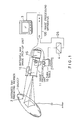
- FIG. 1 shows a schematic configuration according to this invention and an infrared ray radiating member 2 for being tracking is attached at a predetermined position on an object 1 such as a ballooon and the like.
- the infrared ray radiating member 2 may be whatever irradiates infrared rays to an infrared ray image pick-up unit 12 positioned in the coaxial direction of an image projecting unit 11 (such as a slide or cinema projector, in addition, a laser beam projector, a video projector or the like).
- An image is projected on the object 1 by the directional image projecting unit 11 provided on an electrically-driven turn table 10, and the infrared ray image pick-up unit 12 having a field of view catching the infrared ray radiating member 2 is fixed on the image projecting unit 11 in one body.
- the image projecting unit 11 can project arbitrarily in horizontal and vertical directions with exact directivity by driving the electrically-driven turn table 10.
- Video signals VS from the infrared ray image pick-up unit 12 are image-processed by an image processing apparatus 100 which is explained hereinafter, and the processed image frame is displayed on a monitor 3 such as a CRT and the like.
- Drive signals DS processed by the image processing apparatus 100 drive the turn table 10 via a driving section 4 of an amplifier or the like to control the projecting position of the image projecting unit 11, so as to track the shift of the object 1, the infrared ray radiating member 2, or the target point keeping a fixed distance away from the object 1 and the infrared ray radiating member 2.
- the infrared ray radiating member 2 attached on the object 1 irradiates infrared rays to the infrared ray image pick-up unit 12 positioned in the coaxial direction of the image projecting unit 11, the infrared ray image pick-up unit 12 attached to the image projecting unit 11 catches a high luminous point as an image and the video signals VS are binarized in the image processing apparatus 100.
- a central value of a primary moment on a binary image is calculated on real time, for example, every 1/60 second, and signals corresponding to the movement amount are transmitted on the basis of the positional data to the electrically-driven turn table 10 of the image projecting unit 11 via the driving section 4.
- the electrically-driven turn table 10 is controlled by the transmitted signals so that the projecting direction of the image projecting unit 11 may be automatically changed and automatic follow-up projecting may be carried out for the moving object 1, the infrared ray radiating member 2 or the target point keeping a fixed distance away from the object 1 and the infrared ray radiating member 2.
- the image processing apparatus 100 is mainly described in details, the image projecting unit 11 mounted on the electrically-driven turn table 10 is rotated in the horizontal direction by a motor 13, and in the vertical direction by a motor 14. A projecting operation to the arbitrarily directions can be carried out in combination with these rotations.
- the video signals VS are inputted to a binarizing circuit 101, and converted into binary signals P (x, y) represented by "0" or "1" with a predetermined threshold level T.
- FIG .3 shows a relation between image information (oblique line part) and X-Y address, and illustrate that f (x, y) is a video signal VS on an address x and an address y.
- P (x, y) 1
- the video signals VS are inputted to a synchronous separating circuit 102 in which they are divided into horizontal synchronous signals HD and vertical synchronous signals VD, and these divided signals HD and VD are inputted into a timing signal generating circuit 103.
- Clock signals CLK from a clock generating circuit 104 have been inputted into the timing signal generating circuit 103 and the clock signals CLK have been outputted at the timing in response to the horizontal resolution of an image.
- the timing signal generating circuit 103 outputs the clock signals CLK which are inputted into accumulating circuits 110, 112 and an area counting circuit 111, and outputs signals R indicating a measuring region of the image information and similarly outputted signals R are inputted into the accumulating circuit 110, 112 and the area counting circuit 111.
- the timing generating circuit 103 generates horizontal address signals XAD to input them into the accumulating circuit 110, and also generates vertical address signals YAD to input them into the accumulating circuit 112, thereby generating signals YR indicating the completion of measuring to input them into calculating circuits 120 and 130.
- the each timing for the vertical synchronous signals, the signals R indicating the measuring region, and the signals YR indicating the completion of measuring is shown in FIG .4.
- the accumulating circuit 110 calculates ⁇ ⁇ Y, the both circuits 110 and 112 are the same configuration. That is, the accumulating circuit 110 as shown in FIG.5 comprises an AND circuit 113 and an adding circuit 114 and the adding circuit 114 is activated to add the address signals XAD sequentially at the timing of the clock signals CLK only when the both binary signal P (x, y) and signals R indicating the measuring region are "1" and an enable signal ES is also "1".
- the adding circuit 114 is also cleared by inputting the vertical synchronous signal VD, and the added output ⁇ ⁇ X representes ⁇ ⁇ P (x, y) ⁇ x.
- the output ⁇ ⁇ Y of the accumulating circuit 112 represents ⁇ ⁇ P (x, y) ⁇ y.
- These added values ⁇ X and ⁇ Y are inputted into the calculating circuits 120 and 130 respectively.
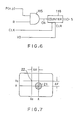
- the configuration of the area counting circuit 111 is as shown in FIG .6, a counter 116 to be cleared by the vertical synchronous signals VD, counting with the clock signals CLK the output CN from the AND circuit 115 into which the binary signals P (x, y) and the signals R indicating the measuring region are inputted, outputs are S as a counted value.
- the counted area S is inputted into the calculating circuits 120 and 130.
- FIG .4 shows the circumstances, wherein the S, ⁇ X, ⁇ Y are initialized by the input of the vertical synchronous signals VD (at the time points t0 and t1) , and the S, ⁇ X, ⁇ Y are measured during the time span T0, and the measured values are renewed during the time span T1.
- Calculating circuits 121 and 131 calculate the differences ⁇ X and ⁇ Y between the center position 21 of the infrared ray radiating member 2 and the target position 22 as shown in FIG.7.
- the center position 21 of the infrared ray radiating member 2 corresponds with the target position 22, through it is also allowed that tracking operation may be carried out keeping a fixed distance away from the infrared ray radiating member 2.
- the differences ⁇ X and ⁇ Y calculated by the calculating circuits 121 and 131 are inputted into motor controllers 4X and 4Y respectively, and the motor controllers 4X and 4Y drive motors 13 and 14 respectively. The differences after the operation described above are fed back so that a deviation between the target position 2 and the center of an image becomes to zero.
- the target position for projecting can be changed adding a setting device capable of setting a position from outside.
- the configuration as mentioned above is all provided with hardwares by using the calculating circuits 120, 121 and 130, 131, through a configuration with software can be also possible by using such as a microcomputor in accordance with a flow chart shown in FIG. 8.
- an infrared ray radiating member 2 is set at the position beyond the image projecting region
- an infrared ray radiating member can be set within the image projecting region and visible light can be applied to the light emitting member.
- a visible light is applied to the light emitting member, a normal kind of an image pick-up means is available.
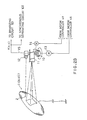
- FIG.9 another configuration as shown in FIG .9 may be also available for the automatic follow-up projecting system wherein an infrared ray reflective medium 20 is mounted in place of the infrared ray radiating member 2 and an infrared ray irradiating unit 15 is provided on the electrically-driven turn table 10, so that an infrared ray image pick-up unit 12 can catch light amount of the reflected infrared rays from the infrared ray reflective medium 20. Visible light can be also applied to this embodiment.
- the configurations of the blocks as shown in FIG.5 and FIG.6 are not limited by this embodiment. In case that the follow-up operation is carried out using the infrared rays, the effect is considerably appreciable, particularly at night because the light for the automatic follow-up is invisible.
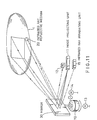
- the image projecting unit 11, the infrared ray image pick-up unit 12 and an infrared ray irradiating unit 15 are attached to the electrically-driven turn table 10, therefore it is difficult to control in direction the system directly by the electrically-driven turn table 10 when these units are large sized or overweighted.
- a mirror 30 such as surface-evaporated mirror or the like is adapted to be attached to the electrically-driven turn table 10 while the image projecting unit 11, the infrared ray image pick-up unit 12 and the infrared ray irradiating unit 15 may be fixed at a separated place.
- an incident image also reaches through the reflection of the mirror 30 to the infrared ray image pick-up unit 12, yet the control of the mirror 30 is carried out in the same way when a mirror is not applied.
- this invention can be applied to a camera capable of automatically following up a subject by using a camera for film, video or the like in place of the image projecting unit 11.
- the use of the automatic follow-up projecting system according to this invention requires no operator, and allows a high speed, responsive smooth tracking. Because the system can steady track a moving object to project an image thereon, it is possible that an advertising image may be projected onto an airship or a balloon, alternatively news may be announced with a character image and/or animation being projected, and many other variation of the applications can be expected according to this invention.
Landscapes
- Physics & Mathematics (AREA)
- General Physics & Mathematics (AREA)
- Theoretical Computer Science (AREA)
- Marketing (AREA)
- Accounting & Taxation (AREA)
- Engineering & Computer Science (AREA)
- Business, Economics & Management (AREA)
- Projection Apparatus (AREA)
- Transforming Electric Information Into Light Information (AREA)
- Closed-Circuit Television Systems (AREA)
- Length Measuring Devices By Optical Means (AREA)
- Control Of Position Or Direction (AREA)
- Details Of Garments (AREA)
- Burglar Alarm Systems (AREA)
- Optical Radar Systems And Details Thereof (AREA)
Applications Claiming Priority (2)
| Application Number | Priority Date | Filing Date | Title |
|---|---|---|---|
| JP37943/90 | 1990-02-19 | ||
| JP2037943A JP2575910B2 (ja) | 1990-02-19 | 1990-02-19 | 自動追尾投影装置 |
Publications (2)
| Publication Number | Publication Date |
|---|---|
| EP0447610A1 true EP0447610A1 (fr) | 1991-09-25 |
| EP0447610B1 EP0447610B1 (fr) | 1994-05-25 |
Family
ID=12511636
Family Applications (1)
| Application Number | Title | Priority Date | Filing Date |
|---|---|---|---|
| EP90117667A Expired - Lifetime EP0447610B1 (fr) | 1990-02-19 | 1990-09-13 | Système de projection avec suivi automatique |
Country Status (8)
| Country | Link |
|---|---|
| US (1) | US5114224A (fr) |
| EP (1) | EP0447610B1 (fr) |
| JP (1) | JP2575910B2 (fr) |
| KR (1) | KR930009520B1 (fr) |
| AT (1) | ATE106155T1 (fr) |
| CA (1) | CA2025808C (fr) |
| DE (1) | DE69009172T2 (fr) |
| ES (1) | ES2053044T3 (fr) |
Cited By (6)
| Publication number | Priority date | Publication date | Assignee | Title |
|---|---|---|---|---|
| EP1107052A4 (fr) * | 1999-06-10 | 2006-12-27 | Sony Corp | Procede et appareil de projection d'images, et appareil pour commander la projection d'images |
| AT503756B1 (de) * | 2003-02-27 | 2008-05-15 | Vrvis Zentrum Fuer Virtual Rea | Verfahren und vorrichtung zur rechnergestützten bestimmung von position und orientierung mindestens eines beweglichen objekts |
| WO2015138148A1 (fr) * | 2014-03-10 | 2015-09-17 | Microsoft Technology Licensing, Llc | Réduction de latence dans des systèmes de projection à caméra |
| CN105453163A (zh) * | 2013-07-05 | 2016-03-30 | 国立大学法人东京大学 | 信息呈现装置 |
| WO2016051018A1 (fr) * | 2014-10-02 | 2016-04-07 | Taikateatteri 13 Ry | Agencement destiné à produire des effets visuels et procédé correspondant |
| US20190225350A1 (en) * | 2016-10-14 | 2019-07-25 | Panasonic Intellectual Property Management Co., Ltd. | Projection system, projection method, flying object system, and flying object |
Families Citing this family (29)
| Publication number | Priority date | Publication date | Assignee | Title |
|---|---|---|---|---|
| US5235363A (en) * | 1991-05-10 | 1993-08-10 | Nview Corporation | Method and apparatus for interacting with a computer generated projected image |
| DE4204821A1 (de) * | 1992-02-18 | 1993-08-19 | Burkhard Katz | Verfahren und vorrichtung fuer die praesentation von darstellungen vor den passagieren von sich bewegenden fahrzeugen |
| US5400095A (en) * | 1993-05-11 | 1995-03-21 | Proxima Corporation | Display projection method and apparatus an optical input device therefor |
| JPH0876082A (ja) * | 1994-06-28 | 1996-03-22 | Sharp Corp | 投影表示装置 |
| JP3735158B2 (ja) * | 1996-06-06 | 2006-01-18 | オリンパス株式会社 | 画像投影システム、画像処理装置 |
| US6554434B2 (en) * | 2001-07-06 | 2003-04-29 | Sony Corporation | Interactive projection system |
| US20030169339A1 (en) * | 2001-10-01 | 2003-09-11 | Digeo. Inc. | System and method for tracking an object during video communication |
| JP2003131319A (ja) * | 2001-10-25 | 2003-05-09 | Seiko Epson Corp | 光送受装置 |
| TWI261723B (en) * | 2003-05-09 | 2006-09-11 | Benq Corp | Projector for adjusting a screen size and brightness depending on various environment and a method thereof |
| US20050128437A1 (en) * | 2003-12-12 | 2005-06-16 | International Business Machines Corporation | System and method for positioning projectors in space to steer projections and afford interaction |
| US7055963B2 (en) * | 2004-03-01 | 2006-06-06 | Belliveau Richard S | Content optimizing system for an image projection lighting device |
| KR100638367B1 (ko) * | 2004-10-30 | 2006-10-25 | 한국과학기술연구원 | 비행 스크린 기구의 비행 궤적 추적을 이용한 자동 영상디스플레이 장치 |
| WO2007052261A2 (fr) * | 2005-10-31 | 2007-05-10 | Mark Fireman | Systeme de projection sur ecran |
| JP4594272B2 (ja) * | 2006-04-26 | 2010-12-08 | 日本電信電話株式会社 | 位置データ変換装置及び位置データ変換方法 |
| JP4611932B2 (ja) * | 2006-05-17 | 2011-01-12 | 日本電信電話株式会社 | 移動体追従撮影投影装置 |
| US20080224041A1 (en) * | 2007-03-16 | 2008-09-18 | Cannamela John J | Method and apparatus for subsurface anomaly detection and image projection |
| FR2938665B1 (fr) * | 2008-11-18 | 2011-01-21 | Optinnova | Dispositif de visualisation interactif optiquement a hauteur de projection variable |
| US8549418B2 (en) * | 2009-12-23 | 2013-10-01 | Intel Corporation | Projected display to enhance computer device use |
| US20120001017A1 (en) * | 2010-07-02 | 2012-01-05 | John Paul Strachan | Installation platform for deploying an earth-based sensor network utilizing a projected pattern from a height |
| CN102495639A (zh) * | 2011-12-02 | 2012-06-13 | 天津工业大学 | 目标跟踪实验装置 |
| WO2015137341A1 (fr) * | 2014-03-12 | 2015-09-17 | コニカミノルタ株式会社 | Dispositif de projection de lumière et procédé de projection de lumière |
| FR3021784B1 (fr) * | 2014-05-27 | 2017-10-13 | European Aeronautic Defence & Space Co Eads France | Procede de projection de donnees virtuelles et dispositif permettant cette projection |
| CN104524731A (zh) * | 2015-01-14 | 2015-04-22 | 南京国业科技有限公司 | 基于光电转塔的多信息融合智能水炮系统 |
| CN207601498U (zh) * | 2017-12-28 | 2018-07-10 | 广景视睿科技(深圳)有限公司 | 一种互动投影装置及烛台灯 |
| JP7236680B2 (ja) | 2018-02-09 | 2023-03-10 | パナソニックIpマネジメント株式会社 | 投影システム |
| DE102019105225B4 (de) * | 2019-03-01 | 2023-10-19 | Deutsches Zentrum für Luft- und Raumfahrt e.V. | System und Verfahren zum Aufnehmen mindestens eines Bildes eines Beobachtungsbereiches |
| WO2021134569A1 (fr) * | 2019-12-31 | 2021-07-08 | 李庆远 | Écran d'affichage flottant à projection interne |
| WO2021161689A1 (fr) * | 2020-02-10 | 2021-08-19 | ソニーグループ株式会社 | Appareil de traitement d'informations, système de traitement d'informations, procédé de traitement d'informations et programme |
| CN113920283B (zh) * | 2021-12-13 | 2022-03-08 | 中国海洋大学 | 基于聚类分析和特征过滤的红外图像尾迹检测及提取方法 |
Citations (2)
| Publication number | Priority date | Publication date | Assignee | Title |
|---|---|---|---|---|
| FR614464A (fr) * | 1926-04-13 | 1926-12-15 | Dispositif aérien et lumineux de publicité | |
| DE3202432A1 (de) * | 1982-01-26 | 1983-08-04 | Messerschmitt-Bölkow-Blohm GmbH, 8000 München | Hochenergielaser-feintracker |
Family Cites Families (8)
| Publication number | Priority date | Publication date | Assignee | Title |
|---|---|---|---|---|
| US1099207A (en) * | 1910-01-19 | 1914-06-09 | Jacob Saudek | Device for combining motion acts and moving pictures. |
| US2796802A (en) * | 1953-12-15 | 1957-06-25 | Farrell Edward M | Rotatable outdoor advertising projection display billboard device |
| US2854886A (en) * | 1955-08-25 | 1958-10-07 | John M Stroud | System for viewing and plotting targets from rapidly changing data |
| US3912385A (en) * | 1973-07-02 | 1975-10-14 | Columbia Scient Ind | Multi-media projector stand |
| US4406428A (en) * | 1980-05-22 | 1983-09-27 | Ferris Carlisle K | Camouflaged aircraft |
| US4515450A (en) * | 1982-09-29 | 1985-05-07 | Mcdonnell Douglas Corporation | Transparency for use with a flying spot scanner to generate images |
| JPS62102185U (fr) * | 1985-12-18 | 1987-06-29 | ||
| US4876444A (en) * | 1988-03-07 | 1989-10-24 | Tennant Company | Protection from extraneous light for light guided vehicle |
-
1990
- 1990-02-19 JP JP2037943A patent/JP2575910B2/ja not_active Expired - Fee Related
- 1990-07-24 US US07/556,978 patent/US5114224A/en not_active Expired - Fee Related
- 1990-09-13 EP EP90117667A patent/EP0447610B1/fr not_active Expired - Lifetime
- 1990-09-13 DE DE69009172T patent/DE69009172T2/de not_active Expired - Fee Related
- 1990-09-13 AT AT90117667T patent/ATE106155T1/de not_active IP Right Cessation
- 1990-09-13 ES ES90117667T patent/ES2053044T3/es not_active Expired - Lifetime
- 1990-09-20 CA CA002025808A patent/CA2025808C/fr not_active Expired - Fee Related
- 1990-12-14 KR KR1019900020560A patent/KR930009520B1/ko not_active Expired - Fee Related
Patent Citations (2)
| Publication number | Priority date | Publication date | Assignee | Title |
|---|---|---|---|---|
| FR614464A (fr) * | 1926-04-13 | 1926-12-15 | Dispositif aérien et lumineux de publicité | |
| DE3202432A1 (de) * | 1982-01-26 | 1983-08-04 | Messerschmitt-Bölkow-Blohm GmbH, 8000 München | Hochenergielaser-feintracker |
Non-Patent Citations (1)
| Title |
|---|
| QUANTUM ELECTRONICS; PROCEEDINGS OF THE THIRD INTERNATIONAL CONGRESS, Dunod, Paris, 1964, pages 1319-1332; H.H. PLOTKIN: "The S-66 laser satellite tracking experiment" * |
Cited By (13)
| Publication number | Priority date | Publication date | Assignee | Title |
|---|---|---|---|---|
| EP1107052A4 (fr) * | 1999-06-10 | 2006-12-27 | Sony Corp | Procede et appareil de projection d'images, et appareil pour commander la projection d'images |
| AT503756B1 (de) * | 2003-02-27 | 2008-05-15 | Vrvis Zentrum Fuer Virtual Rea | Verfahren und vorrichtung zur rechnergestützten bestimmung von position und orientierung mindestens eines beweglichen objekts |
| CN105453163B (zh) * | 2013-07-05 | 2019-02-22 | 国立大学法人东京大学 | 信息呈现装置 |
| CN105453163A (zh) * | 2013-07-05 | 2016-03-30 | 国立大学法人东京大学 | 信息呈现装置 |
| WO2015138148A1 (fr) * | 2014-03-10 | 2015-09-17 | Microsoft Technology Licensing, Llc | Réduction de latence dans des systèmes de projection à caméra |
| CN106105184B (zh) * | 2014-03-10 | 2019-10-18 | 微软技术许可有限责任公司 | 相机投影系统中的延时降低 |
| CN106105184A (zh) * | 2014-03-10 | 2016-11-09 | 微软技术许可有限责任公司 | 相机投影系统中的延时降低 |
| US10181193B2 (en) | 2014-03-10 | 2019-01-15 | Microsoft Technology Licensing, Llc | Latency reduction in camera-projection systems |
| US10039995B2 (en) | 2014-10-02 | 2018-08-07 | D.I.E Tech Oy | Arrangement for providing visual effects and related method |
| WO2016051018A1 (fr) * | 2014-10-02 | 2016-04-07 | Taikateatteri 13 Ry | Agencement destiné à produire des effets visuels et procédé correspondant |
| US20190225350A1 (en) * | 2016-10-14 | 2019-07-25 | Panasonic Intellectual Property Management Co., Ltd. | Projection system, projection method, flying object system, and flying object |
| EP3506625A4 (fr) * | 2016-10-14 | 2019-08-28 | Panasonic Intellectual Property Management Co., Ltd. | Système de projection, procédé de projection, système d'objet volant et objet volant |
| US10780990B2 (en) | 2016-10-14 | 2020-09-22 | Panasonic Intellectual Property Management Co., Ltd. | Projection system, projection method, flying object system, and flying object |
Also Published As
| Publication number | Publication date |
|---|---|
| DE69009172T2 (de) | 1994-09-08 |
| CA2025808A1 (fr) | 1993-08-17 |
| JP2575910B2 (ja) | 1997-01-29 |
| JPH0418613A (ja) | 1992-01-22 |
| CA2025808C (fr) | 1993-08-17 |
| ES2053044T3 (es) | 1994-07-16 |
| KR930009520B1 (ko) | 1993-10-06 |
| DE69009172D1 (de) | 1994-06-30 |
| ATE106155T1 (de) | 1994-06-15 |
| US5114224A (en) | 1992-05-19 |
| KR910015880A (ko) | 1991-09-30 |
| EP0447610B1 (fr) | 1994-05-25 |
Similar Documents
| Publication | Publication Date | Title |
|---|---|---|
| EP0447610B1 (fr) | Système de projection avec suivi automatique | |
| US5023709A (en) | Automatic follow-up lighting system | |
| US5580140A (en) | Device for the presentation of images to the passengers of moving vehicles | |
| US5497188A (en) | Method for virtualizing an environment | |
| CA2148231A1 (fr) | Systeme de commande automatique des mouvements de camera | |
| US20050259150A1 (en) | Air-floating image display apparatus | |
| US7027041B2 (en) | Presentation system | |
| CN116783885A (zh) | 激光投影设备及其提示方法 | |
| JP2830839B2 (ja) | 距離計測装置 | |
| CN104917957A (zh) | 用于控制摄像机成像的设备及其系统 | |
| JP2986428B2 (ja) | ターゲットプロジェクタの自動整列システム | |
| US5479225A (en) | Automatic focusing projector | |
| JP2000155839A (ja) | 標識領域画像抽出方法、装置、標識領域画像抽出プログラムを記録した記録媒体 | |
| US20060088188A1 (en) | Method for the detection of an obstacle | |
| JPS626115A (ja) | 距離測定装置 | |
| US7394051B2 (en) | Image-based tracking system for model train control | |
| JPS63284990A (ja) | ビデオカメラの追跡装置 | |
| JPH0728166A (ja) | ビデオプロジェクター装置 | |
| JPH02123877A (ja) | 移動物体の自動追尾装置 | |
| KR20260011444A (ko) | 정밀도로지도 기반의 검지영역 설정 자동화 및 이를 이용한 근거리 및 원거리 순환형 영상식 돌발상황 검지 시스템 | |
| NL1009232C2 (nl) | Projectiesysteem. | |
| SU1081416A1 (ru) | Устройство дл считывани изображени со снимков | |
| JPS62261002A (ja) | 光切断法により円形突起物の位置を3次元的に認識する装置 | |
| JPH09312729A (ja) | 画像出力装置 | |
| JP3198004B2 (ja) | 移動体の位置検出装置 |
Legal Events
| Date | Code | Title | Description |
|---|---|---|---|
| PUAI | Public reference made under article 153(3) epc to a published international application that has entered the european phase |
Free format text: ORIGINAL CODE: 0009012 |
|
| AK | Designated contracting states |
Kind code of ref document: A1 Designated state(s): AT BE CH DE ES FR GB GR IT LI LU NL SE |
|
| 17P | Request for examination filed |
Effective date: 19920218 |
|
| 17Q | First examination report despatched |
Effective date: 19930716 |
|
| GRAA | (expected) grant |
Free format text: ORIGINAL CODE: 0009210 |
|
| AK | Designated contracting states |
Kind code of ref document: B1 Designated state(s): AT BE CH DE ES FR GB GR IT LI LU NL SE |
|
| REF | Corresponds to: |
Ref document number: 106155 Country of ref document: AT Date of ref document: 19940615 Kind code of ref document: T |
|
| ITF | It: translation for a ep patent filed | ||
| REF | Corresponds to: |
Ref document number: 69009172 Country of ref document: DE Date of ref document: 19940630 |
|
| ET | Fr: translation filed | ||
| REG | Reference to a national code |
Ref country code: ES Ref legal event code: FG2A Ref document number: 2053044 Country of ref document: ES Kind code of ref document: T3 |
|
| PGFP | Annual fee paid to national office [announced via postgrant information from national office to epo] |
Ref country code: BE Payment date: 19940722 Year of fee payment: 5 |
|
| PGFP | Annual fee paid to national office [announced via postgrant information from national office to epo] |
Ref country code: GR Payment date: 19940727 Year of fee payment: 5 |
|
| PGFP | Annual fee paid to national office [announced via postgrant information from national office to epo] |
Ref country code: LU Payment date: 19940801 Year of fee payment: 5 |
|
| PGFP | Annual fee paid to national office [announced via postgrant information from national office to epo] |
Ref country code: SE Payment date: 19940822 Year of fee payment: 5 |
|
| REG | Reference to a national code |
Ref country code: GR Ref legal event code: FG4A Free format text: 3012110 |
|
| PGFP | Annual fee paid to national office [announced via postgrant information from national office to epo] |
Ref country code: AT Payment date: 19940922 Year of fee payment: 5 |
|
| PGFP | Annual fee paid to national office [announced via postgrant information from national office to epo] |
Ref country code: ES Payment date: 19940923 Year of fee payment: 5 |
|
| PGFP | Annual fee paid to national office [announced via postgrant information from national office to epo] |
Ref country code: NL Payment date: 19940930 Year of fee payment: 5 |
|
| PGFP | Annual fee paid to national office [announced via postgrant information from national office to epo] |
Ref country code: CH Payment date: 19941019 Year of fee payment: 5 |
|
| EAL | Se: european patent in force in sweden |
Ref document number: 90117667.7 |
|
| PLBE | No opposition filed within time limit |
Free format text: ORIGINAL CODE: 0009261 |
|
| STAA | Information on the status of an ep patent application or granted ep patent |
Free format text: STATUS: NO OPPOSITION FILED WITHIN TIME LIMIT |
|
| 26N | No opposition filed | ||
| PG25 | Lapsed in a contracting state [announced via postgrant information from national office to epo] |
Ref country code: LU Free format text: LAPSE BECAUSE OF NON-PAYMENT OF DUE FEES Effective date: 19950913 Ref country code: AT Effective date: 19950913 |
|
| PG25 | Lapsed in a contracting state [announced via postgrant information from national office to epo] |
Ref country code: SE Effective date: 19950914 Ref country code: ES Free format text: LAPSE BECAUSE OF EXPIRATION OF PROTECTION Effective date: 19950914 |
|
| PG25 | Lapsed in a contracting state [announced via postgrant information from national office to epo] |
Ref country code: LI Effective date: 19950930 Ref country code: CH Effective date: 19950930 Ref country code: BE Effective date: 19950930 |
|
| BERE | Be: lapsed |
Owner name: AOI STUDIO CO. LTD Effective date: 19950930 Owner name: DENTSU PROX INC. Effective date: 19950930 |
|
| PG25 | Lapsed in a contracting state [announced via postgrant information from national office to epo] |
Ref country code: GR Free format text: THE PATENT HAS BEEN ANNULLED BY A DECISION OF A NATIONAL AUTHORITY Effective date: 19960331 |
|
| PG25 | Lapsed in a contracting state [announced via postgrant information from national office to epo] |
Ref country code: NL Effective date: 19960401 |
|
| REG | Reference to a national code |
Ref country code: CH Ref legal event code: PL |
|
| REG | Reference to a national code |
Ref country code: GR Ref legal event code: MM2A Free format text: 3012110 |
|
| NLV4 | Nl: lapsed or anulled due to non-payment of the annual fee |
Effective date: 19960401 |
|
| EUG | Se: european patent has lapsed |
Ref document number: 90117667.7 |
|
| PGFP | Annual fee paid to national office [announced via postgrant information from national office to epo] |
Ref country code: GB Payment date: 19970926 Year of fee payment: 8 |
|
| PG25 | Lapsed in a contracting state [announced via postgrant information from national office to epo] |
Ref country code: GB Free format text: LAPSE BECAUSE OF NON-PAYMENT OF DUE FEES Effective date: 19980913 |
|
| GBPC | Gb: european patent ceased through non-payment of renewal fee |
Effective date: 19980913 |
|
| REG | Reference to a national code |
Ref country code: ES Ref legal event code: FD2A Effective date: 19990601 |
|
| PGFP | Annual fee paid to national office [announced via postgrant information from national office to epo] |
Ref country code: FR Payment date: 20010917 Year of fee payment: 12 |
|
| PGFP | Annual fee paid to national office [announced via postgrant information from national office to epo] |
Ref country code: DE Payment date: 20011120 Year of fee payment: 12 |
|
| PG25 | Lapsed in a contracting state [announced via postgrant information from national office to epo] |
Ref country code: DE Free format text: LAPSE BECAUSE OF NON-PAYMENT OF DUE FEES Effective date: 20030401 |
|
| PG25 | Lapsed in a contracting state [announced via postgrant information from national office to epo] |
Ref country code: FR Free format text: LAPSE BECAUSE OF NON-PAYMENT OF DUE FEES Effective date: 20030603 |
|
| REG | Reference to a national code |
Ref country code: FR Ref legal event code: ST |
|
| PG25 | Lapsed in a contracting state [announced via postgrant information from national office to epo] |
Ref country code: IT Free format text: LAPSE BECAUSE OF NON-PAYMENT OF DUE FEES;WARNING: LAPSES OF ITALIAN PATENTS WITH EFFECTIVE DATE BEFORE 2007 MAY HAVE OCCURRED AT ANY TIME BEFORE 2007. THE CORRECT EFFECTIVE DATE MAY BE DIFFERENT FROM THE ONE RECORDED. Effective date: 20050913 |