EP0447700A1 - Faseroptischer Richtkoppler - Google Patents
Faseroptischer Richtkoppler Download PDFInfo
- Publication number
- EP0447700A1 EP0447700A1 EP90302943A EP90302943A EP0447700A1 EP 0447700 A1 EP0447700 A1 EP 0447700A1 EP 90302943 A EP90302943 A EP 90302943A EP 90302943 A EP90302943 A EP 90302943A EP 0447700 A1 EP0447700 A1 EP 0447700A1
- Authority
- EP
- European Patent Office
- Prior art keywords
- optical fiber
- optical fibers
- fiber coupler
- fused
- component
- Prior art date
- Legal status (The legal status is an assumption and is not a legal conclusion. Google has not performed a legal analysis and makes no representation as to the accuracy of the status listed.)
- Granted
Links
- 239000013307 optical fiber Substances 0.000 title claims abstract description 296
- 239000000463 material Substances 0.000 claims abstract description 21
- 239000011248 coating agent Substances 0.000 claims abstract description 4
- 238000000576 coating method Methods 0.000 claims abstract description 4
- 239000000835 fiber Substances 0.000 claims description 42
- 239000006185 dispersion Substances 0.000 claims description 33
- VYPSYNLAJGMNEJ-UHFFFAOYSA-N Silicium dioxide Chemical compound O=[Si]=O VYPSYNLAJGMNEJ-UHFFFAOYSA-N 0.000 claims description 29
- PXGOKWXKJXAPGV-UHFFFAOYSA-N Fluorine Chemical compound FF PXGOKWXKJXAPGV-UHFFFAOYSA-N 0.000 claims description 16
- 229910052731 fluorine Inorganic materials 0.000 claims description 16
- 239000011737 fluorine Substances 0.000 claims description 16
- ZOXJGFHDIHLPTG-UHFFFAOYSA-N Boron Chemical compound [B] ZOXJGFHDIHLPTG-UHFFFAOYSA-N 0.000 claims 4
- 239000000654 additive Substances 0.000 claims 4
- 230000000996 additive effect Effects 0.000 claims 4
- 229910052796 boron Inorganic materials 0.000 claims 4
- 239000002019 doping agent Substances 0.000 claims 4
- 230000003287 optical effect Effects 0.000 abstract description 43
- 238000010168 coupling process Methods 0.000 abstract description 32
- 230000008878 coupling Effects 0.000 abstract description 31
- 238000005859 coupling reaction Methods 0.000 abstract description 31
- 238000009826 distribution Methods 0.000 abstract description 13
- 230000007423 decrease Effects 0.000 abstract description 8
- 239000011162 core material Substances 0.000 description 69
- 239000010453 quartz Substances 0.000 description 17
- 235000012239 silicon dioxide Nutrition 0.000 description 17
- 238000005452 bending Methods 0.000 description 14
- 238000010438 heat treatment Methods 0.000 description 4
- 238000000034 method Methods 0.000 description 4
- 230000000644 propagated effect Effects 0.000 description 4
- 230000003247 decreasing effect Effects 0.000 description 3
- 238000003780 insertion Methods 0.000 description 3
- 230000037431 insertion Effects 0.000 description 3
- 230000015572 biosynthetic process Effects 0.000 description 2
- 230000000694 effects Effects 0.000 description 2
- 230000005540 biological transmission Effects 0.000 description 1
- 238000004891 communication Methods 0.000 description 1
- 230000001276 controlling effect Effects 0.000 description 1
- 238000010586 diagram Methods 0.000 description 1
- 238000002474 experimental method Methods 0.000 description 1
- 239000003365 glass fiber Substances 0.000 description 1
- 238000004519 manufacturing process Methods 0.000 description 1
- 230000001105 regulatory effect Effects 0.000 description 1
- 239000007858 starting material Substances 0.000 description 1
Images


Classifications
-
- G—PHYSICS
- G02—OPTICS
- G02B—OPTICAL ELEMENTS, SYSTEMS OR APPARATUS
- G02B6/00—Light guides; Structural details of arrangements comprising light guides and other optical elements, e.g. couplings
- G02B6/24—Coupling light guides
- G02B6/26—Optical coupling means
- G02B6/28—Optical coupling means having data bus means, i.e. plural waveguides interconnected and providing an inherently bidirectional system by mixing and splitting signals
- G02B6/293—Optical coupling means having data bus means, i.e. plural waveguides interconnected and providing an inherently bidirectional system by mixing and splitting signals with wavelength selective means
- G02B6/29331—Optical coupling means having data bus means, i.e. plural waveguides interconnected and providing an inherently bidirectional system by mixing and splitting signals with wavelength selective means operating by evanescent wave coupling
- G02B6/29332—Wavelength selective couplers, i.e. based on evanescent coupling between light guides, e.g. fused fibre couplers with transverse coupling between fibres having different propagation constant wavelength dependency
-
- G—PHYSICS
- G02—OPTICS
- G02B—OPTICAL ELEMENTS, SYSTEMS OR APPARATUS
- G02B6/00—Light guides; Structural details of arrangements comprising light guides and other optical elements, e.g. couplings
- G02B6/24—Coupling light guides
- G02B6/26—Optical coupling means
- G02B6/28—Optical coupling means having data bus means, i.e. plural waveguides interconnected and providing an inherently bidirectional system by mixing and splitting signals
- G02B6/2804—Optical coupling means having data bus means, i.e. plural waveguides interconnected and providing an inherently bidirectional system by mixing and splitting signals forming multipart couplers without wavelength selective elements, e.g. "T" couplers, star couplers
- G02B6/2821—Optical coupling means having data bus means, i.e. plural waveguides interconnected and providing an inherently bidirectional system by mixing and splitting signals forming multipart couplers without wavelength selective elements, e.g. "T" couplers, star couplers using lateral coupling between contiguous fibres to split or combine optical signals
- G02B6/2835—Optical coupling means having data bus means, i.e. plural waveguides interconnected and providing an inherently bidirectional system by mixing and splitting signals forming multipart couplers without wavelength selective elements, e.g. "T" couplers, star couplers using lateral coupling between contiguous fibres to split or combine optical signals formed or shaped by thermal treatment, e.g. couplers
Definitions
- the present invention concerns optical fiber couplers employed in communication systems.
- two or more fibers are aligned side by side in a plane and thermally fused and elongated, thereby forming a fused-elongated region.
- each component optical fiber is reduced, as is the diameter of the core of each fiber.
- a proportionately larger fraction of the light propagated therein leaks through the clad which surrounds the core of each fiber.
- the distance between the cores of adjacent optical fibers is reduced, and due to this fact, the coupling between the propagated modes of the individual fibers becomes extremely great. In this way, the light signal carried by one fiber branches and is thus caused to be multiplexed over two or more optical fibers.
- the present invention provides an optical fiber coupler characterized in that, for a defined section in which two or more component optical fibers are thermally fused and elongated thereby forming a fused-elongated region which constitutes the optical fiber coupler, that at least one of the component optical fibers is formed from a single mode optical fiber material employed within a parameter range in which the mode field diameter increases monotonically with decrease in the diameter of the optical fiber core.
- the optical fiber coupler provided by the present invention is further characterized in that, when using optical fibers from which a portion of the coating material has been removed thereby exposing the clad, and by aligning two or more of such component optical fibers side by side in a plane and mutually thermally fusing the exposed clad of adjacent optical fibers, after which the fused region is drawn out, thereby forming a fused-elongated region which constitutes the optical fiber coupler, for such an optical fiber coupler, optical fiber material is used in which the softening temperature of the core is higher than that of the clad, and further, for the drawing out of the mutually fused sections, the tension employed is such that by virtue of remaining stress, the refractive index of the core is reduced.
- the optical fiber coupler By so forming the optical fiber coupler, it is possible to reduce the difference in refractive index between the core and the clad, widen the mode power distribution, and thereby achieve optical coupling between adjacent optical fibers. Furthermore, because the amount of elongation or drawing of the fibers which is carried out after fusing the fibers need not be extreme while still achieving adequate optical coupling, it is thereby possible to improve the mechanical strength of the fused-elongated region. Moreover, because the amount of drawing of the component fibers after fusing and hence reduction in the diameters of their respective cores is limited, it possible to create optical fiber couplers with low optical losses. By limiting the formation of curvature in the couplers, losses can be further lessened.
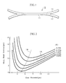
- Fig. 1 is a side view of the optical fiber coupler of the first preferred embodiment of the present invention.
- Fig. 2 is a graph illustrating the relationship between core diameter and diameter of the mode field for a single mode optical fiber.
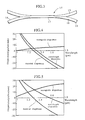
- Fig. 3 is a side view of the optical fiber coupler of the second preferred embodiment of the present invention.
- Figs. 4 and 5 are graphs illustrating the relationship between wavelength and dispersion for the optical fibers.
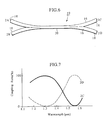
- Fig. 6 is a side view of the optical fiber coupler of the third preferred embodiment of the present invention.
- Fig. 7 is a graph illustrating one example of the relationship between wavelength and coupling ratio for the optical fiber coupler shown in Fig. 6.
- Fig. 8 is a side view of the optical fiber coupler of the fourth preferred embodiment of the present invention.
- Fig. 9 is a graph illustrating the relationship between the relative difference of the refractive index for the core and that for the clad and the tension applied during elongation for the optical fiber employed in the optical fiber coupler shown in Fig. 8.
- Figs. 10 through 12 are views of key points in the graph of Fig. 9 in which the relationship between the relative difference of the refractive index for the core and that for the clad and the tension applied during elongation is expressed in terms of the distribution of refractive index for the optical fiber.
- Figs. 13 and 14 are illustrations of the power distribution in a fused section and a fused-elongated section respectively in an optical fiber coupler.
- Fig. 15 is a side view of the optical fiber coupler of the fifth preferred embodiment of the present invention.
- Fig. 16 is a side view of the optical fiber coupler of the sixth preferred embodiment of the present invention.
- Fig. 17 is a side view of the optical fiber coupler of the seventh preferred embodiment of the present invention.
- Figs. 18 and 19 are diagrams illustrating the dependance of degree of optical coupling on wavelength for the optical fiber couplers shown in Figs. 15 and 16.
- the optical fiber coupler 11 of the present embodiment as shown in Fig. 1 consists of a fused-elongated region 14 formed by thermally fusing and then drawing out a section of each of two component optical fibers 12 and 13, one of which is an conventional quartz single mode optical fiber 12 (hereafter referred to as conventional fiber), and one of which is a single mode optical fiber 13 characterized by having a parameter range in which the mode field diameter increases monotonically with decrease in the diameter of the optical fiber core.
- Fig. 2 the relationship between core diameter and mode field diameter for conventional quartz single mode optical fiber suitable for transmitting optical signals at a wavelength of 1.3 ⁇ m is graphically illustrated.
- a series of approximately parallel curves are shown, each of which represents a fiber having a different value for the refractive index difference between the clad and the core.
- a curve has a respective minimum value for the mode field diameter corresponding with a particular value for the diameter of the fiber core.
- the line 1B in the drawing interconnects the minimum values of the respective curves.
- the above mentioned refractive index difference (RRID) is calculated by Equ. 1 below in which m1 represents the refractive index for the core material and m2 represents the refractive index for the core material.
- the region 1A relates to a range for the structural parameters characteristic of the conventional quartz single mode optical fiber, the structural parameters being as follows: core diameter 9 - 10 ⁇ m, refractive index difference 0.28 - 0.35 %, external diameter of clad 125 ⁇ m. As shown in the graph, the region 1A corresponds to a relatively low mode field diameter, and thus indicates a parameter range not very suitable for the fully formed optical fiber coupler. Further, this region 1A is significantly to the right of the above mentioned line 1B which coincides with minimum values of mode field diameter for various examples of the optical fiber.
- one of the two fibers which are fused together to form the coupler is a single mode optical fiber 13 characterized by having a parameter range in which the mode field diameter increases monotonically with decrease in the diameter of the optical fiber core, the amount of drawing out of the fused component fibers can be limited to a relatively small amount while still achieving adequate optical coupling. For this reason, it is possible to fabricate a small sized optical fiber coupler 11.
- optical fiber coupler 11 of this first preferred embodiment only one conventional fiber 12 and one single mode optical fiber 13 each were employed.
- the coupler may also be manufactured using only two or more of the single mode optical fibers 13.
- a single mode quartz optical fiber having a core diameter of 9 ⁇ m, an external clad diameter of 125 ⁇ m, and a refractive index difference of 0.3 %, for the single mode optical fiber 13 a portion of each were aligned side by side and thermally fused.
- the fused portion was then draw out to produce an optical fiber coupler 11 of the same type as that of the first preferred embodiment as shown in Fig. 1.
- the fused-elongated region 14 thus manufactured had a minimum outer diameter of 45 ⁇ m, and a length of 7 mm.
- the measured value for loss from the thus produced optical fiber coupler 11 was 0.1 dB which is extremely low.
- the optical fiber coupler 15 of the present embodiment as shown in Fig. 3 consists of a fused-elongated region 17 formed by thermally fusing and then drawing out a section of each of two component optical fibers 12 and 16, one of which is the previously described conventional fiber 12, and one of which is a single mode optical fiber 16 characterized by having negligible wavelength dispersion and being a dispersion shifted optical fiber at wavelengths of 1.4 ⁇ m and greater (hereafter referred to as dispersion shifted fiber 16).
- the bending loss characteristics are extremely good, and the refractive index difference ( ⁇ %) is comparatively high. Additionally, the core diameter is such that the structural parameters lie in the region to the left of the line 1B in Fig. 2.
- optical fiber material for which the refractive index difference is high, and for which the core diameter is such that the structural parameters lie in the region to the left of the line 1B in Fig. 2.
- the so called wave guide dispersion is high.
- Figs. 4 and 5 examples of the wavelength dispersion characteristics can be seen for conventional optical fiber suitable for transmitting light signals at a wavelength of 1.3 ⁇ m of which the refractive index difference is high and of which the core diameter is small.
- the wave guide dispersion is low, and in the vicinity of 1.3 ⁇ m, the wavelength dispersion representing the sum of the wave guide dispersion and materials dispersion is zero.
- Concerning the above mentioned wave guide dispersion because the measured value varies with respect to the wavelength of the propagated light, the mode propagation state also varies.
- the mode propagation velocity also varies.
- the optical fiber material again has a refractive index difference which is high and a small core diameter.
- the wave guide dispersion is high. Due to the high wave guide dispersion, the wavelength dispersion is shifted towards longer wavelengths.
- the above mentioned dispersion shifted fiber 16 is an example of an optical fiber material for which the wave guide dispersion has been intentionally shifted to a higher value in this way.
- the wavelength at which the wavelength dispersion value becomes zero is shifted to a wavelength longer than 1.3 ⁇ m, and is generally in the range of 1.4 - 1.6 ⁇ m.
- the propagation constant of the respective component optical fibers 12, 16 can be varied to match desired values.
- desired propagation constant for the two component fibers 12, 16 which are different and then thermally fusing together a portion of each component optical fiber 12, 16 and drawing out the fused portion as described above to form the fused-elongated region 17, the wavelength dependance characteristics of the resulting optical fiber coupler 15 can be controlled.
- an optical fiber coupler which is largely wavelength independent (or wide band-pass type optical fiber coupler) can be fabricated.
- the resulting optical fiber coupler 15 includes lead fibers 18 leading up to the fused-elongated region 17 for which the stability characteristics in response to fiber bending are supported.
- an optical fiber having a core diameter of 4 ⁇ m, an external clad diameter of 125 ⁇ m, a refractive index difference of 0.7 %, and a zero wavelength dispersion value at 1.55 ⁇ m for the dispersion shifted fiber 16 a portion of each were aligned side by side and thermally fused. The fused portion was then draw out to produce an optical fiber coupler 15 of the same type as that of the second preferred embodiment as shown in Fig. 3.
- the fused-elongated region 17 thus manufactured had a minimum outer diameter of 55 ⁇ m, and a length of 6 mm.
- the measured value for loss from the thus produced optical fiber coupler 15 was 0.05 dB which is extremely low.
- the lead fiber 18 of the optical fiber coupler 15 manufactured as described above was bent in the form of a curve having a bending curvature of 10 mm, the additional optical loss was only 0.1 dB.
- a prior art coupler suitable for light signals at a wavelength of 1.3 ⁇ m bending a lead under the same conditions demonstrated an additional loss of 0.5 dB.
- the optical fiber coupler 15 was minimally wavelength dependant and could be used over a wide range of wavelengths as a wavelength independent optical fiber coupler (wide band-width type optical fiber coupler).
- the optical fiber coupler 19 of the present embodiment as shown in Fig. 3 consists of a fused-elongated region 20 formed by thermally fusing and then drawing out a section of each of two component optical fibers, both of which are the same as the dispersion shifted fiber 16 employed in the optical fiber coupler 15 described above for the second preferred embodiment of the present invention.
- optical fiber coupler 19 of the present embodiment by appropriately controlling the elongation ratio of the fused-elongated region 20, it is possible to fabricate a selective wavelength splitter type optical fiber coupler in which at certain wavelengths, essentially no light is transmitted and at certain other wavelengths, essentially 100 % transmission is achieved.
- optical fiber coupler 19 By constructing the optical fiber coupler 19 using two of the dispersion shifted fibers 16, of which only one is employed in the optical fiber coupler 15 described above for the second preferred embodiment, an optical fiber coupler 19 with even greater stability characteristics in response to bending can be fabricated.
- the fused-elongated region 20 thus manufactured had a minimum outer diameter of 55 ⁇ m, and a length of 10 mm.
- the optical fiber coupler 19 could be used as a selective wavelength splitter type optical fiber coupler. That is to say, of the four ports 2A, 2B, 2C, 2D, when an optical signal containing two wavelength components, one at 1.3 ⁇ m and one at 1.55 ⁇ m, was input at port 2A, it was found that the optical signal was separated into its two components, one emitted from port 2C and one emitted from port 2D.
- the optical fiber coupler 21 of the present embodiment as shown in Fig. 8 consists of a fused-elongated region 25 formed by thermally fusing the clad from a section of each of two component optical fibers 24 and then drawing out the fused section, both of the optical fibers 24 being such that the softening temperature of the core 23 is higher than that of the clad 22.
- the tension employed is such that by virtue of remaining stress, the refractive index of the cores of the fused sections is reduced.
- a suitable example is optical fiber material having a core 23 of essentially pure quartz (SiO2) and a clad 22 containing added fluorine to thereby cause the clad to have a lower refractive index than the core.
- SiO2 essentially pure quartz
- clad 22 containing added fluorine to thereby cause the clad to have a lower refractive index than the core.
- the viscosity coefficient of the clad 22 is lower, by appropriately choosing the temperature used during elongation of the fused sections so that only the clad 22 is in a moldable state, is possible to impose a degree of elastic strain only in the core 23 which is controllable by the amount of tension applied during elongation.
- the elastic strain imposed on the core 23 due to the strain dependant optical properties of the core material, the refractive index of the core 23 is decreased, while that of the clad 22 is not effected.
- a graph is shown which demonstrates the relationship between the amount of tension applied during elongation of the heated optical fiber 24 and the lowering of the refractive index difference by decreasing the refractive index of the core material.
- an optical fiber material was used having a core diameter of 11 ⁇ m and a clad outer diameter of 125 ⁇ m.
- the amount of tension applied during elongation of the optical fiber 24 is increased, the refractive index difference between the core and clad decreases.
- the refractive index distribution is shown for the optical fiber 24.
- the power distribution (P) of the propagation mode becomes wider and shorter, and is essentially shifted peripherally.
- Figs. 13 and 14 the power distribution for the fused-elongated region 25 of the optical fiber coupler 21 of the present embodiment is schematically illustrated.
- Fig. 13 is the power distribution for the fused optical fibers 24 prior to elongation and
- Fig. 14 is the power distribution for the fused-elongated optical fibers 24 which constitute the fused-elongated region 25 of the optical fiber coupler 21.
- Fig. 13 there is no overlapping of the power distributions of the two component optical fibers 24 and hence no optical coupling can occur.
- the fused, and furthermore elongated optical fibers 24 shown in Fig. 14 there is good overlap of the power distributions emanating from the somewhat narrowed cores 23 in the fused-elongated region 25 so that the optical signal of one of the component optical fibers 24 can seep into and hence couple with the adjacent optical fiber.
- optical fiber coupler 21 of the present embodiment adequate optical coupling can be achieved without extreme elongation of the component optical fibers 24, and hence extreme reduction in the diameters of their cores. Accordingly, the mechanical strength of the optical fiber coupler 21 can be improved. Further, optical losses caused by bending of the optical fiber coupler 21 can be lessened.
- the fused region formed as described above was heated to a relatively low temperature on the order of 1300 o C and drawn out at a pulling tension of 50 g, whereby the diameter of the fused section was reduced by about 10 %.
- the heating temperature was rapidly lowered to thereby produce an optical fiber coupler 21 the same as that of the fourth preferred embodiment as shown in Fig. 8.
- the length of the section of initially fused optical fibers 24 was 100 ⁇ m, however, this length can be up to 1 to 2 mm for the same type of optical fiber coupler 21.
- an optical fiber coupler 21 was fabricated in which the length of the section of initially fused optical fibers 24 was 1 mm with all other conditions being the same. The optical fiber coupler 21 thereby produced demonstrated optical losses of 0.3 dB.
- the optical fiber coupler 26 of the present embodiment as shown in Fig. 15 consists of a twisted fused-elongated region 27 formed by thermally fusing the clad from a section of each of two component optical fibers 24 identical to those of the above fourth preferred embodiment and then drawing out the fused section while twisting the pair of optical fibers 24.
- the tension employed is such that by virtue of remaining stress, the refractive index of the cores of the fused sections is reduced.
- optical fiber coupler 26 of the present embodiment as was the case with the optical fiber coupler 21 of the fourth preferred embodiment shown in Fig. 8, essentially by decreasing the refractive index difference between the core and clad and thereby broadening the mode power distribution, suitable optical coupling between the fused sections of optical fiber 24 can be achieved. Accordingly, without extremely reducing the diameter of the fused-elongated region 27, adequate optical coupling is possible. Thus, the mechanical strength of the optical fiber coupler 26 can be improved. Further, optical losses caused by bending of the optical fiber coupler 26 can be lessened.
- the fused region formed as described above was heated to a relatively low temperature on the order of 1300 o C and drawn out at a tension of 50 g, whereby the diameter of the fused section was reduced by about 10 %.
- the heating temperature was rapidly lowered to thereby produce an optical fiber coupler 26 the same as that of the fifth preferred embodiment as shown in Fig. 15.
- the length of the section of initially fused optical fibers 24 was 100 ⁇ m, however, this length can be up to 1 to 2 mm for the same type of optical fiber coupler 26.
- an optical fiber coupler 26 was fabricated in which the length of the section of initially fused optical fibers 24 was 1 mm with all other conditions being the same. The optical fiber coupler 26 thereby produced demonstrated insertion losses of 0.3 dB.
- the optical fiber coupler 28 of the present embodiment as shown in Fig. 16 consists of a fused-elongated region 30 formed by thermally fusing the clad from a section of each of two component optical fibers 29 having a quartz glass core of which the refractive index was reduced 0.1 % or less by the addition of fluorine, and a quartz glass clad of which the refractive index was adjusted to a level lower than that of the core by the addition of fluorine, and then drawing out the fused section.
- the tension employed is such that by virtue of remaining stress, the refractive index of the cores of the fused sections is reduced.
- the reason for using a glass fiber for which the refractive index of the core is reduced 0.1 % or less as described above is to facilitate the formation of an optical fiber coupler 28 having a suitable refractive index difference between the core and clad.
- the component optical fibers 29 employed in the present preferred embodiment can have a core-clad refractive index difference even lower than that of the component optical fibers 24 employed in the fourth and fifth preferred embodiments, effective optical coupling between the fused sections of optical fiber 29 can be achieved with even less elongation and hence diameter reduction. Accordingly, the mechanical strength of the optical fiber coupler 28 can be further improved and insertion losses caused by bending of the optical fiber coupler 28 can be further lessened.
- the fused region formed as described above was heated to a relatively low temperature on the order of 1300 o C and drawn out at a pulling tension of 50 g, whereby the diameter of the fused section was reduced by about 10 %.
- the heating temperature was rapidly lowered to thereby produce an optical fiber coupler 28 the same as that of the sixth preferred embodiment as shown in Fig. 16.
- a suitable degree of optical coupling between the two component optical fibers 29 can be achieved.
- the degree of optical coupling for the optical fiber coupler 28 thereby obtained was then measured and it was found that 51 % optical coupling was obtained between port 2E and port 2G shown in Fig.
- the length of the section of initially fused optical fibers 29 was 100 ⁇ m, however, this length can be up to 1 to 2 mm for the same type of optical fiber coupler 28.
- an optical fiber coupler 28 was fabricated in which the length of the section of initially fused optical fibers 29 was 1 mm with all other conditions being the same. The optical fiber coupler 28 thereby produced demonstrated losses of 0.3 dB.
- the optical fiber coupler 31 of the present embodiment as shown in Fig. 17 consists of a fused-elongated region 33 formed by lining up and thermally fusing the clad from a section of each of two component optical fibers, an optical fiber 29 identical to that employed in the above sixth preferred embodiment, and an optical fiber 32 having a core of a lesser diameter than that of the optical fiber 29, and then drawing out the fused section.
- the tension employed is such that by virtue of remaining stress, the refractive index of the cores of the fused sections is reduced.
- the phase constant is different for each of the component optical fibers 29, 32.
- optical coupling in the optical fiber coupler 31 is largely wavelength independent, as demonstrated by the fairly flat curve in Fig. 18 which shows the degree of optical coupling between port 2I and 2L as a function of wavelength of the light for the optical fiber coupler 31 shown in Fig. 17.
- the coupling ratio differs with changing wavelength of the transmitted light, with virtually 100 % coupling occurring at certain specific wavelengths of the transmitted light.
- Fig. 19 when an optical signal containing two wavelength components, was input at port 2E of the optical fiber coupler 28 shown in Fig. 16, it was found that the optical signal was separated into its two components, one emitted from port 2G and one emitted from port 2H.
- those optical fiber couplers employing two identical optical fibers can be used as a selective wavelength splitter type optical fiber coupler.
- optical fiber coupler 31 of the present preferred embodiment because the phase constant is different for each of the component optical fibers 29, 32, optical coupling in the optical fiber coupler 31 is largely wavelength independent. Accordingly, the optical fiber coupler 31 can be used over a wide range of wavelengths as a wavelength independent optical fiber coupler (wide band-pass type optical fiber coupler).
- an optical fibers 29 having a core diameter of 10 ⁇ m, a clad external diameter of 125 ⁇ m, a refractive index difference prior to elongation of 0.32 %, a core of quartz incorporating added fluorine, and a quartz clad incorporating added fluorine
- an optical fiber 32 having a core diameter of 9 ⁇ m a clad external diameter of 125 ⁇ m, a refractive index difference prior to elongation of 0.32 %, a core of quartz incorporating added fluorine, and a quartz clad incorporating added fluorine
- 100 ⁇ m portions from each of the component optical fibers 29 were aligned side by side and thermally fused using a sufficiently high temperature so as to form a roughly cylindrical fused portion which was then drawn out produce a fused region having a diameter of approximately 125 ⁇ m.
- the fused region formed as described above was heated to a relatively low temperature on the order of 1300 o C and drawn out at a tension of 50 g, whereby the diameter of the fused section was reduced by about 10 %. Finally, while the above described pulling tension was maintained, the heating temperature was rapidly lowered to thereby produce an optical fiber coupler 31 the same as that of the seventh preferred embodiment as shown in Fig. 17.
- the length of the section of initially fused optical fibers 29, 32 was 100 ⁇ m, however, this length can be up to 1 to 2 mm for the same type of optical fiber coupler 31.
- an optical fiber coupler 31 was fabricated in which the length of the section of initially fused optical fibers 29 was 1 mm with all other conditions being the same. The optical fiber coupler 31 thereby produced demonstrated optical losses of 0.3 dB.
- optical fiber coupler of the present invention includes all forms encompassed by the appended claims.
Landscapes
- Physics & Mathematics (AREA)
- General Physics & Mathematics (AREA)
- Optics & Photonics (AREA)
- Optical Couplings Of Light Guides (AREA)
- Mechanical Coupling Of Light Guides (AREA)
Priority Applications (2)
| Application Number | Priority Date | Filing Date | Title |
|---|---|---|---|
| DE1990614602 DE69014602T2 (de) | 1990-03-19 | 1990-03-19 | Faseroptischer Richtkoppler. |
| EP94107139A EP0610973B1 (de) | 1990-03-07 | 1990-03-19 | Faseroptischer Koppler |
Applications Claiming Priority (1)
| Application Number | Priority Date | Filing Date | Title |
|---|---|---|---|
| US07/490,026 US5066087A (en) | 1990-03-07 | 1990-03-07 | Optical fiber coupler |
Related Child Applications (2)
| Application Number | Title | Priority Date | Filing Date |
|---|---|---|---|
| EP94107139A Division EP0610973B1 (de) | 1990-03-07 | 1990-03-19 | Faseroptischer Koppler |
| EP94107139.1 Division-Into | 1990-03-19 |
Publications (2)
| Publication Number | Publication Date |
|---|---|
| EP0447700A1 true EP0447700A1 (de) | 1991-09-25 |
| EP0447700B1 EP0447700B1 (de) | 1994-11-30 |
Family
ID=23946309
Family Applications (2)
| Application Number | Title | Priority Date | Filing Date |
|---|---|---|---|
| EP94107139A Expired - Lifetime EP0610973B1 (de) | 1990-03-07 | 1990-03-19 | Faseroptischer Koppler |
| EP90302943A Expired - Lifetime EP0447700B1 (de) | 1990-03-07 | 1990-03-19 | Faseroptischer Richtkoppler |
Family Applications Before (1)
| Application Number | Title | Priority Date | Filing Date |
|---|---|---|---|
| EP94107139A Expired - Lifetime EP0610973B1 (de) | 1990-03-07 | 1990-03-19 | Faseroptischer Koppler |
Country Status (2)
| Country | Link |
|---|---|
| US (1) | US5066087A (de) |
| EP (2) | EP0610973B1 (de) |
Cited By (3)
| Publication number | Priority date | Publication date | Assignee | Title |
|---|---|---|---|---|
| EP0582894A1 (de) * | 1992-07-29 | 1994-02-16 | Sumitomo Electric Industries, Limited | Optische Faser zur Umwandlung des Modenfelddurchmessers |
| EP0576299A3 (de) * | 1992-06-25 | 1994-11-02 | Kyocera Corp | Optische Koppler. |
| EP0683408A1 (de) * | 1994-05-20 | 1995-11-22 | SEIKOH GIKEN Co., Ltd. | Multiplexer/Demultiplexer aus optischer Faser mit einer Reflexionsschicht um den optischen Koppelbereich |
Families Citing this family (11)
| Publication number | Priority date | Publication date | Assignee | Title |
|---|---|---|---|---|
| US5179603A (en) * | 1991-03-18 | 1993-01-12 | Corning Incorporated | Optical fiber amplifier and coupler |
| JPH04322207A (ja) * | 1991-04-23 | 1992-11-12 | Japan Aviation Electron Ind Ltd | 光ファイバカプラ |
| JPH05127040A (ja) * | 1991-11-06 | 1993-05-25 | Shin Etsu Chem Co Ltd | フアイバ型光カプラの保持具 |
| US5355426A (en) * | 1992-09-02 | 1994-10-11 | Gould Electronics Inc. | Broadband MXN optical fiber couplers and method of making |
| US5303373A (en) * | 1992-10-16 | 1994-04-12 | Schott Fiber Optics, Inc. | Anamorphic fused fiber optic bundle |
| JPH06250042A (ja) * | 1993-03-01 | 1994-09-09 | Shin Etsu Chem Co Ltd | 広波長域光ファイバ型カプラおよびその製造方法 |
| GB0219141D0 (en) * | 2002-08-16 | 2002-09-25 | Alcatel Optronics Uk Ltd | Optical branching component with low polarisation sensitivity |
| US6826341B2 (en) * | 2002-11-04 | 2004-11-30 | Fitel Usa Corp. | Systems and methods for reducing splice loss in optical fibers |
| GB2395796A (en) | 2002-11-27 | 2004-06-02 | Alcatel Optronics Uk Ltd | Optical waveguide branching component with MMI couplers |
| US7272280B2 (en) * | 2004-12-16 | 2007-09-18 | Honeywell International Inc. | Optical coupler for measuring wavelength |
| WO2009035104A1 (ja) * | 2007-09-14 | 2009-03-19 | Tatsuta Electric Wire & Cable Co., Ltd. | 光ファイバカプラ用光ファイバ及び光ファイバカプラ |
Citations (5)
| Publication number | Priority date | Publication date | Assignee | Title |
|---|---|---|---|---|
| EP0093460A1 (de) * | 1982-03-22 | 1983-11-09 | Koninklijke Philips Electronics N.V. | Verfahren zum Herstellen eines faseroptischen Kopplungselementes |
| WO1987000934A1 (en) * | 1985-07-30 | 1987-02-12 | British Telecommunications Public Limited Company | Optical fused couplers |
| US4755037A (en) * | 1987-04-13 | 1988-07-05 | Mcdonnell Douglas Corporation | Fiber optic coupler |
| GB2207254A (en) * | 1987-07-11 | 1989-01-25 | Stc Plc | Glass-clad optical fibre couplers |
| JPH02108009A (ja) * | 1988-10-18 | 1990-04-19 | Fujikura Ltd | 光ファイバカプラ |
Family Cites Families (2)
| Publication number | Priority date | Publication date | Assignee | Title |
|---|---|---|---|---|
| DE8601064U1 (de) | 1986-01-17 | 1987-05-21 | Robert Bosch Gmbh, 7000 Stuttgart | Kraftstoff-Verteilereinspritzpumpe für Brennkraftmaschinen |
| GB2190762B (en) * | 1986-05-23 | 1989-12-13 | Stc Plc | Directional coupler |
-
1990
- 1990-03-07 US US07/490,026 patent/US5066087A/en not_active Expired - Lifetime
- 1990-03-19 EP EP94107139A patent/EP0610973B1/de not_active Expired - Lifetime
- 1990-03-19 EP EP90302943A patent/EP0447700B1/de not_active Expired - Lifetime
Patent Citations (5)
| Publication number | Priority date | Publication date | Assignee | Title |
|---|---|---|---|---|
| EP0093460A1 (de) * | 1982-03-22 | 1983-11-09 | Koninklijke Philips Electronics N.V. | Verfahren zum Herstellen eines faseroptischen Kopplungselementes |
| WO1987000934A1 (en) * | 1985-07-30 | 1987-02-12 | British Telecommunications Public Limited Company | Optical fused couplers |
| US4755037A (en) * | 1987-04-13 | 1988-07-05 | Mcdonnell Douglas Corporation | Fiber optic coupler |
| GB2207254A (en) * | 1987-07-11 | 1989-01-25 | Stc Plc | Glass-clad optical fibre couplers |
| JPH02108009A (ja) * | 1988-10-18 | 1990-04-19 | Fujikura Ltd | 光ファイバカプラ |
Cited By (5)
| Publication number | Priority date | Publication date | Assignee | Title |
|---|---|---|---|---|
| EP0576299A3 (de) * | 1992-06-25 | 1994-11-02 | Kyocera Corp | Optische Koppler. |
| EP0582894A1 (de) * | 1992-07-29 | 1994-02-16 | Sumitomo Electric Industries, Limited | Optische Faser zur Umwandlung des Modenfelddurchmessers |
| US5446820A (en) * | 1992-07-29 | 1995-08-29 | Sumitomo Electric Industries, Ltd. | Mode field diameter conversion optical fiber |
| AU665100B2 (en) * | 1992-07-29 | 1995-12-14 | Sumitomo Electric Industries, Ltd. | Mode field diameter conversion optical fiber |
| EP0683408A1 (de) * | 1994-05-20 | 1995-11-22 | SEIKOH GIKEN Co., Ltd. | Multiplexer/Demultiplexer aus optischer Faser mit einer Reflexionsschicht um den optischen Koppelbereich |
Also Published As
| Publication number | Publication date |
|---|---|
| US5066087A (en) | 1991-11-19 |
| EP0447700B1 (de) | 1994-11-30 |
| EP0610973B1 (de) | 1999-01-13 |
| EP0610973A3 (de) | 1995-01-18 |
| EP0610973A2 (de) | 1994-08-17 |
Similar Documents
| Publication | Publication Date | Title |
|---|---|---|
| US4798436A (en) | Optical fused couplers | |
| EP0783117B1 (de) | Optische Fasern für optische Dämpfung | |
| US5066087A (en) | Optical fiber coupler | |
| US6272268B1 (en) | Optical couplers with multilayer fibers | |
| US5351325A (en) | Narrow band Mach-Zehnder filter | |
| US6282342B1 (en) | Monolithic coaxial device | |
| WO1998029768A9 (en) | Optical couplers with multilayer fibers | |
| EP0840148B1 (de) | Optischer Faserkoppler und Verfahren zu seiner Herstellung | |
| AU774103B2 (en) | Method of manufacturing polarization-maintaining optical fiber coupler | |
| US5129020A (en) | Wavelength selective optical fiber coupler | |
| US20040170358A1 (en) | Optical fiber coupler and optical fiber therefor | |
| EP0818694B1 (de) | Mach-Zehnder Interferometer mit zusammengesetzten Fasern | |
| EP0308244A2 (de) | Wellenlängen selektiver optischer Richtkoppler | |
| EP0295039A2 (de) | Optischer Wellenleiterkoppler | |
| JP2828251B2 (ja) | 光ファイバカプラ | |
| JP2848832B2 (ja) | 広帯域形光ファイバカプラ | |
| Weidman | A new approach to achromaticity in fused couplers | |
| JPH08220369A (ja) | 光ファイバカプラおよびその製造方法 | |
| JPH04317013A (ja) | 光ファイバカプラ | |
| MXPA00012645A (en) | Monolithic coaxial device |
Legal Events
| Date | Code | Title | Description |
|---|---|---|---|
| PUAI | Public reference made under article 153(3) epc to a published international application that has entered the european phase |
Free format text: ORIGINAL CODE: 0009012 |
|
| 17P | Request for examination filed |
Effective date: 19901127 |
|
| AK | Designated contracting states |
Kind code of ref document: A1 Designated state(s): DE FR GB |
|
| 17Q | First examination report despatched |
Effective date: 19930511 |
|
| GRAA | (expected) grant |
Free format text: ORIGINAL CODE: 0009210 |
|
| AK | Designated contracting states |
Kind code of ref document: B1 Designated state(s): DE FR GB |
|
| XX | Miscellaneous (additional remarks) |
Free format text: TEILANMELDUNG 94107139.1 EINGEREICHT AM 14/10/91. |
|
| REF | Corresponds to: |
Ref document number: 69014602 Country of ref document: DE Date of ref document: 19950112 |
|
| ET | Fr: translation filed | ||
| PLBE | No opposition filed within time limit |
Free format text: ORIGINAL CODE: 0009261 |
|
| STAA | Information on the status of an ep patent application or granted ep patent |
Free format text: STATUS: NO OPPOSITION FILED WITHIN TIME LIMIT |
|
| 26N | No opposition filed | ||
| REG | Reference to a national code |
Ref country code: GB Ref legal event code: IF02 |
|
| PGFP | Annual fee paid to national office [announced via postgrant information from national office to epo] |
Ref country code: DE Payment date: 20080313 Year of fee payment: 19 |
|
| PGFP | Annual fee paid to national office [announced via postgrant information from national office to epo] |
Ref country code: GB Payment date: 20090318 Year of fee payment: 20 |
|
| PGFP | Annual fee paid to national office [announced via postgrant information from national office to epo] |
Ref country code: FR Payment date: 20090316 Year of fee payment: 20 |
|
| PG25 | Lapsed in a contracting state [announced via postgrant information from national office to epo] |
Ref country code: DE Free format text: LAPSE BECAUSE OF NON-PAYMENT OF DUE FEES Effective date: 20091001 |
|
| REG | Reference to a national code |
Ref country code: GB Ref legal event code: PE20 Expiry date: 20100318 |
|
| PG25 | Lapsed in a contracting state [announced via postgrant information from national office to epo] |
Ref country code: GB Free format text: LAPSE BECAUSE OF EXPIRATION OF PROTECTION Effective date: 20100318 |