EP0448015B1 - Système de radiocommunication mobile - Google Patents
Système de radiocommunication mobile Download PDFInfo
- Publication number
- EP0448015B1 EP0448015B1 EP91104154A EP91104154A EP0448015B1 EP 0448015 B1 EP0448015 B1 EP 0448015B1 EP 91104154 A EP91104154 A EP 91104154A EP 91104154 A EP91104154 A EP 91104154A EP 0448015 B1 EP0448015 B1 EP 0448015B1
- Authority
- EP
- European Patent Office
- Prior art keywords
- mobile station
- signal
- base station
- station
- mobile
- Prior art date
- Legal status (The legal status is an assumption and is not a legal conclusion. Google has not performed a legal analysis and makes no representation as to the accuracy of the status listed.)
- Expired - Lifetime
Links
Images





Classifications
-
- H—ELECTRICITY
- H04—ELECTRIC COMMUNICATION TECHNIQUE
- H04B—TRANSMISSION
- H04B7/00—Radio transmission systems, i.e. using radiation field
- H04B7/24—Radio transmission systems, i.e. using radiation field for communication between two or more posts
- H04B7/26—Radio transmission systems, i.e. using radiation field for communication between two or more posts at least one of which is mobile
- H04B7/2643—Radio transmission systems, i.e. using radiation field for communication between two or more posts at least one of which is mobile using time-division multiple access [TDMA]
-
- H—ELECTRICITY
- H04—ELECTRIC COMMUNICATION TECHNIQUE
- H04L—TRANSMISSION OF DIGITAL INFORMATION, e.g. TELEGRAPHIC COMMUNICATION
- H04L1/00—Arrangements for detecting or preventing errors in the information received
- H04L1/20—Arrangements for detecting or preventing errors in the information received using signal quality detector
-
- H—ELECTRICITY
- H04—ELECTRIC COMMUNICATION TECHNIQUE
- H04W—WIRELESS COMMUNICATION NETWORKS
- H04W36/00—Hand-off or reselection arrangements
- H04W36/0005—Control or signalling for completing the hand-off
- H04W36/0055—Transmission or use of information for re-establishing the radio link
- H04W36/0072—Transmission or use of information for re-establishing the radio link of resource information of target access point
-
- H—ELECTRICITY
- H04—ELECTRIC COMMUNICATION TECHNIQUE
- H04W—WIRELESS COMMUNICATION NETWORKS
- H04W36/00—Hand-off or reselection arrangements
- H04W36/24—Reselection being triggered by specific parameters
- H04W36/30—Reselection being triggered by specific parameters by measured or perceived connection quality data
- H04W36/304—Reselection being triggered by specific parameters by measured or perceived connection quality data due to measured or perceived resources with higher communication quality
Definitions
- the present invention generally relates to mobile radio communication systems, and more particularly to a mobile radio communication system which employs a multi-channel access system and is applicable to a mobile telephone or the like using radio zones.
- the mobile radio communication system employs a handover control procedure which enables fast and efficient communication, so that the service and the frequency utilization efficiency are improved.
- EP-A-0 318 033 discloses a mobile radio communication system employing time-divisional multiplex access (TDMA) and comprising a control station which is provided with respect to a control zone, the control zone being made up of a plurality of radio zones; a plurality of base stations, one for each of said radio zones; and a mobile station which is movable within the control zone.
- the mobile station comprises two separate receivers, a first receiver having a mixer and a demodulator for communication with the base stations, and a second receiver also having a mixer and a demodulator for receiving control signals from all base stations.
- the second receiver additionally has a level detector for determining the signal strength of the control signals constantly received from all base stations.
- Each control signal in each base station has a flag, either 0 or 1, indicating if this base stations has a free channel (flag: 1) or not (flag: 0).
- the second receiver provided with the level detector receives the control signals from the base stations and compares the reception levels only of those base stations having free channels (indicated by flag: 1), in order to monitor if the mobile station moves from one radio zone to another radio zone. When based on the comparison of reception levels a change of the radio zone is detected, and a switching request signal is transmitted from the mobile station through a current base station to the exchange or control station, then a switch to a destination base station having a free channel is performed.
- this mobile radio communication system uses signal strength monitoring performed by a second receiver in the mobile station, for determining when the mobile station leaves a particular radio zone covered by a particular base station assigned thereto, and which new radio zone is reached by the mobile station, for performing a handover to the new base station of the new radio zone.
- each base station has to transmit a dedicated control signal containing a flag, which control signal is only used for monitoring a change of radio zones.
- Communication signals are received by the mobile station through the first receiver thereof.
- US-A-4 829 519 discloses that monitoring of signal strength and the use of signal strength monitoring to determine when a transfer from one radio zone to another radio zone is to be made, is in itself inadequate.
- this prior art document suggests that the mobile station should monitor a message transmitted from a base station, and based on this monitoring the mobile station determines a bit or symbol error rate above a threshold relating thereto, and the mobile station automatically sequentially monitors messages from adjacent base stations, such that the mobile station automatically switches from a first to a second base station the message of which has a bit or symbol error rate below threshold.
- the first kind of messages relates to "ordinary" messages which are error corrected in the mobile station for obtaining a correct message, then this corrected message is compared with the received message, and a signal quality assessment is performed based on the bit or symbol error rate.
- a second kind of messages relates to special quality assessment messages which according to the disclosure in this prior art document are preferable over ordinary messages.
- the quality assessment messages are transmitted by the base stations on every outbound channel, resulting in considerable expenditures with respect to the power required for transmissions in every outbound channel of the base stations, for example.
- a handover is made when a called base station changes from an old base station to a new base station.
- the base station of an old radio zone in which the mobile station first exists and the base stations in neighboring radio zones measure the field intensity of a signal from the mobile station.
- a radio zone of the base station which receives the signal from the mobile station with the highest field intensity is regarded as a new radio zone in which the mobile station now exists.
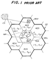
- FIG.1 shows radio zones of an existing analog mobile telephone as an example of the conventional mobile radio communication system which uses the FDMA system and employs the radio zones.
- a control zone CZ surrounded by a bold solid line includes a plurality of radio zones which are under control of a single control station CS.
- the control zone CZ includes seven radio zones RZ1 through RZ7.
- FIG.1 only shows a base station BS1 of the radio zone RZ1 and a base station BS2 of the radio zone RZ2.
- a mobile station MR exists within an arbitrary radio zone RZi within the control zone CZ.
- the mobile station MR may be a mobile telephone set equipped to an automobile or a portable telephone set which is hand carried by the user.
- FIG.2 (A) and (B) respectively show control signals for controlling call-out and call-in
- FIG.3 (A) and (B) respectively show voice signals.
- a radio line uses a control channel C-CH and a voice channel V-CH which are not time-division-multiplexed.
- C-CH control channel
- V-CH voice channel
- one control channel group f1 is assigned to one control zone CZ
- voice channel groups f8 through f14 are respectively assigned to the radio zones RZ1 through RZ7 so that the frequencies of the voice channels do not overlap among the radio zones RZ1 through RZ7 within the same control zone CZ.
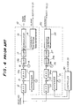
- FIG.4 shows an example of a receiving system of the base station in the conventional mobile radio communication system.
- the receiving system includes a receiver 10 for receiving a voice channel signal, a receiver 20 exclusively for measuring the field intensity of a signal from the mobile station MR for the purpose of determining the radio zone in which the mobile station MR is located, and a controller 30 for controlling synthesizers 11 and 21 of the respective receivers 10 and 20 and the channel frequency in response to an instruction from the control station CS.
- the received signal which passes through a bandpass filter 12 is mixed to a first local signal which has a frequency set by the synthesizer 11 in a mixer 13 and is converted into a signal having a first intermediate frequency.
- the output signal of the mixer 13 is passed through a bandpass filter 14a and is mixed to a second local signal which has a frequency set by a synthesizer 15 and is converted into a signal having a second intermediate frequency in a mixer 16.
- the output signal of the mixer 16 is passed through a bandpass filter 14b and is amplified by an intermediate frequency amplifier 17.
- a field intensity detector 18 detects the field intensity of the received signal based on an output signal of the intermediate frequency amplifier 17 and notifies the detected field intensity to the control station CS.
- a demodulator 19 demodulates the output signal of the intermediate frequency amplifier 17 and outputs an audio signal.
- the received signal which passes through a bandpass filter 22 is mixed to a first local signal which has a frequency set by the synthesizer 21 in a mixer 23 and is converted into a signal having a first intermediate frequency.
- the output signal of the mixer 23 is passed through a bandpass filter 24a and is mixed to a second local signal which has a frequency set by a synthesizer 25 and is converted into a signal having a second intermediate frequency in a mixer 26.
- the output signal of the mixer 26 is passed through a bandpass filter 24b and is amplified by an intermediate frequency amplifier 27.
- a field intensity detector 28 detects the field intensity of the received signal based on an output signal of the intermediate frequency amplifier 27 and notifies the detected field intensity to the control station CS.
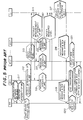
- FIG.5 is a time chart for explaining a handover control procedure of the conventional mobile radio communication system which uses the base station shown in FIG.4.
- the mobile station MR first exists within the radio zone RZ1 as shown in FIG.1 and communicates via the base station BS1 of the radio zone RZ1, and that the synthesizer 11 within the receiver 10 is tuned to the frequency of the mobile station MR in response to a frequency control signal from the controller 30 which receives an instruction from the control station CS.
- the field intensity detector 18 within the receiver 10 constantly monitors the field intensity of the signal from the mobile station MR in a step S11.
- the field intensity of the signal from the mobile station MR gradually decreases at the base station BS1.
- the base station BS1 detects that the field intensity of the signal from the mobile station MR is less than a predetermined threshold value in a step S12, the base station BS1 notifies this information to the control station CS which controls the base station BS1 and the other neighboring base stations BS2 through BS7 within the control zone CZ in a step S13.
- the control station CS instructs all of the base stations BS1 through BS7 within the control zone CZ including the base station BS1 to measure the field intensity of the signal received from the mobile station MR in a step S14.
- the synthesizer 21 of the receiver 20 within each of the base stations BS1 through BS7 is tuned to the frequency of the mobile station MR, so that the field intensity of the signal received from the mobile station MR is output from the field intensity detector 28 within each of the base stations BS1 through BS7 within the control zone CZ in a step S15.
- the base stations BS1 through BS7 respectively notify the measured field intensity of the signal received from the mobile station MR to the control station CS in a step S16.
- the control station CS compares the field intensities notified from the base stations BS1 through BS7 and selects one of the base stations BS1 through BS7 which outputs the highest field intensity, and at the same time, selects an available channel (or free frequency) out of the voice channel groups f9 through f14 which are assigned to the base stations BS1 through BS7, in a step S17.
- the control station CS When it is assumed for the sake of convenience that the field intensity level notified from the base station BS2 is the highest, the control station CS notifies the base station BS1 of a handoff message and a new voice channel selected from the voice channel group f9 in a step S18 because the mobile station MR has now moved into the radio zone RZ2.
- This handoff message indicates that the communication between the communicating mobile station MR and the base station BS1 is ending.
- the base station BS1 transmits the received handoff message and the new voice channel to the mobile station MR and disconnects the transmission on the going line in a step S19.
- the control station CS notifies the handoff message and the new voice channel to the base station BS2 because the mobile station MR has now moved into the radio zone RZ2. Hence, the base station BS2 is put ready to transmit using the new voice channel.
- the mobile station MR switches from the voice channel V-CH which is being used to the new voice channel in a step S20.
- the base station BS2 starts a communication with the mobile station MR using the new voice channel of the mobile station MR in a step S21.
- the voice channel between the base station BS2 and the mobile station MR is established in the above described manner.
- control zone CZ includes a plurality of radio zones RZ and each radio zone RZ has a radius in the order of several km, many mobile stations MR which require the handover may exist approximately at the same time.
- the control station CS of the conventional system monitors the radio zones RZ1 through RZ7 within the control zone CZ, the control station CS cannot process the handovers which are simultaneously generated in a plurality of radio zones RZ within the control zone CZ.
- each base station BS is only provided with a limited number of receivers 10 and 20, the base station BS cannot measure the field intensities of the signals which are simultaneously received from a plurality of mobile stations MR. As a result, there is a problem in that the handover process must wait until the turn of the mobile station MR comes.
- the base station BS must be provided with the receiver 20 for measuring the field intensity of the signal from the mobile station MR in addition to the normal receiver 10 which is used for the communication.
- the mobile radio communication system of the present invention it is possible to prevent the mobile station from waiting for the handover even when a plurality of mobile stations within the same control zone simultaneously request handovers.
- both the control signal and the voice signal continuously exist for predetermined time periods according to the conventional mobile radio communication system which uses the multi-channel access system. For this reason, the channels are occupied during the predetermined time periods and cannot be used for other purposes.
- the present invention employs the time division multiplexing access (TDMA) system which time divides both the control signal and the voice signal in time slots as shown in FIGS.6 and 7.
- TDMA time division multiplexing access
- FIG.6 (A) and (B) respectively show the control signal transmitted from the base station BS to the mobile station MR and the control signal transmitted from the mobile station MR to the base station BS.
- FIG.7 (A) and (B) respectively show the voice signal transmitted from the base station BS to the mobile station MR and the voice signal transmitted from the mobile station MR to the base station BS.
- both the control signal and the voice signal are constantly transmitted on the going line. But the receiver of a mobile station MR does not receive any information during time slots other than a time slot which is assigned to this mobile station MR. For example, when the time slot "a" is assigned to the mobile station MR, the receiver of this mobile station MR does not receive any information during the time slots "b" and "c".
- a control channel C-CH is assigned to each radio zone RZ, and the receiving system of the mobile station MR can measure the field intensity or signal strength of the signals from each of the base stations BS at an arbitrary time by scanning the frequencies of the control signals of the neighboring base stations BS during a time slot other than the time slot used by the mobile station MR.
- the frequencies of the control signals which are scanned correspond to the frequency groups fl through f7 of the control signals assigned to each of the radio zones RZ, for example, as will be described later.
- the time slot other than the time slot used by the mobile station MR is a free time slot.
- the time slot "a" is used as the control channel C-CH
- the time slots "b" and "c" are used either as the control channel C-CH or the voice channel V-CH (control/voice channel C/V-CH).
- each mobile station MR can measure the field intensity or signal strength of the signals from each of the base stations BS at an arbitrary time by scanning the frequency groups f8 through f14 of the voice signals during a free time slot other than the time slot ("a" in the above example) used by the mobile station MR, even when the signals are carriers transmitted from the base stations BS.
- FIG.8 is a time chart for explaining the operation of the mobile radio communication system according to the present invention
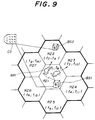
- FIG.9 shows radio zones employed by the present invention.
- steps which are the same as those corresponding steps in FIG.5 are designated by the same reference numerals, and a description thereof will be omitted.
- parts which are the same as those corresponding parts in FIG.1 are designated by the same reference numerals, and a description thereof will be omitted.
- frequency groups f1 through f7 are respectively assigned to the control channels C-CH of the radio zones RZ1 through RZ7, and the frequency groups f8 through f14 are respectively assigned to the voice channels V-CH of the radio zones RZ1 through RZ7.
- the mobile station MR constantly monitors the quality of the radio line in a step S1 shown in FIG.8 based on the field intensity or signal strength of the signal received from the base station BS1 and the code error rate of the demodulated signal.
- the mobile station MR moves from the radio zone RZ1 to the radio zone RZ2, for example, the mobile station MR detects that the signal strength or the code error rate has deteriorated and is now outside a tolerable range in a step S2.
- the mobile station MR uses a free time slot which is other than the time slot used by the mobile station MR for the communication with the base station BS1, and successively detects the signal strengths of the voice signals or the control signals from each of the neighboring base stations BS2 through BS7 in a step S3, where the control signals have frequencies corresponding to the radio zones RZ2 through RZ7 which are covered by the respective base stations BS2 through BS7.
- the mobile station MR determines the highest signal strength among the detected signal strengths in a step S4, so as to determine the base station which is to succeed the communication of the base station BS1.
- the base station BS2 succeeds the communication of the base station BS1 with the mobile station MR.
- the result of the determination made in the step S4 is sent from the mobile station MR to the base station BS1 to request a handover in a step S5.
- the base station BS1 which is communicating sends a handover request message to the control station CS in a step S6 in response to the handover request from the mobile station MR.
- the handover process becomes possible.
- the control station CS selects as the new voice channel the channel for communicating with the new base station BS2 of the radio zone RZ2 in which the mobile station MR is located.
- the control station CS notifies the handover message and the new voice channel to the mobile station MR, the base station BS1 which is communicating with the mobile station MR, and the new base station BS2 which is to succeed the communication of the base station BS1.
- the mobile station MR ends the communication with the base station BS1 and starts a communication with the new base station BS2 using the new voice channel.
- FIG.10 shows a receiving system of a mobile station which is used in this embodiment.
- those parts which are the same as those corresponding parts in FIG.4 are designated by the same reference numerals, and a description thereof will be omitted.
- a receiver 1 has the same construction as receiver 10 shown in FIG.4.
- An error rate detector 2 constantly detects the code error rate of the demodulated signal of the voice channel V-CH which is used for the communication between the mobile station MR and the base station BS, so as to detect the quality of the radio line.
- a circuit 3 compares the code error rate detected by the error rate detector 2 with a threshold value and compares the signal strength detected by the signal strength or field intensity detector 18 with a threshold value, and detects a deterioration of the communication quality when the code error rate and the signal strength are less than the respective threshold values for more than a predetermined time.
- the circuit 3 includes timers 31 and 32, and an OR circuit 33 which are connected as shown.
- a controller 4 controls the synthesizer 11 when the deterioration is detected by the circuit 3 or in response to an instruction from the control station CS.
- a maximum field intensity or signal strength detector 5 compares the signal strengths or field intensities of the control signals or the voice signals from each of the base stations BS measured by the detector 18 with a timing with which the controller 4 successively switches the tuning frequency of the synthesizer 11 for the control signal or the voice signal, and detects the base station BS from which the signal having the highest field intensity or signal strength is received.
- a transmitter 6 includes a modulator 61, a mixer 62, and a bandpass filter 63 which are connected as shown.
- the modulator 61 modulates an output signal of the maximum field intensity or signal strength detector 5.
- the mixer 62 mixes an output signal of the modulator 61 and the output signal of the synthesizer 11, and converts the signals into a signal having a desired transmission frequency.
- the bandpass filter 63 limits the band of the output signal of the mixer 62 into a predetermined band.
- the error rate detector 2 may detect the code error rate using the Viterbi code.
- the code error rate can be detected by counting the number of times the error correction is made.
- FIG.11 shows an embodiment of the error rate detector 2.
- the error rate detector 2 includes an error correction circuit 202, a timer 203 and a counter 204 which are connected as shown.
- the error correction circuit 202 receives the output of the demodulator 19 shown in FIG.10 via a terminal 201 and carries out an error correction.
- a demodulated signal is output from the error correction circuit 202 via a terminal 205.
- the timer 203 is set with a predetermined time, and the counter 204 counts the number of times the error correction is carried out in the error correction circuit 202 within the predetermined time set in the timer 203.
- An output signal of the counter 204 is supplied to the timer 31 shown in FIG.10 via a terminal 206.
- FIG.12 shows an embodiment of the maximum field intensity or signal strength detector 5.
- the detector 5 includes a comparator 502, a switch 503 and a zone determining circuit 504 which are connected as shown.
- the output signal of the field intensity or signal strength detector 18 shown in FIG.10 is applied to a terminal 501 and is output from a terminal 505 to be supplied to the timer 32 on one hand, and is supplied to terminals A of the comparator 502 and the switch 503 on the other.
- An output signal of the switch 503 is supplied to terminals B of the comparator 502 and the switch 503.
- the comparator 502 compares the magnitude of the field intensity or signal strength presently detected and received at the terminal A with the magnitude of the field intensity or signal strength previously detected and received at the terminal B, and outputs a signal which controls the switch 503 to connect to one of the terminals A and B which receives the field intensity or signal strength with the greater magnitude.
- the signal from the controller 4 shown in FIG.10 is supplied to the zone determining circuit 504 via a terminal 506, and the zone determining circuit 504 determines that the base station BS from which the field intensity last supplied to the terminal A originates is the base station BS of the radio zone RZ in which the mobile station MR is now located.
- An output signal of the zone determining circuit 504 indicative of this determination is supplied to the transmitter 6 shown in FIG.10 via a terminal 507.
- the mobile station MR is communicating with the base station BS1 using the time slot "a" of the voice channel V-CH.
- the controller 4 controls the synthesizer 11 based on the output of the OR circuit 33 so as to successively detect the field intensities or signal strengths of the signals from the neighboring base stations BS2 through BS7 (step S3).
- the synthesizer 11 uses the time slots "b" and "c” to successively scan the frequencies f2 through f7 of the control signals respectively assigned to the base stations BS2 through BS7.
- the mobile station MR which corresponds to the control/voice channel C/V-CH of the control signal shown in FIG.6 may continue to transmit a carrier or a dummy signal even when this mobile station MR is not communicating.
- the field intensities or signal strengths of the control signals assigned to each of the radio zones RZ2 through RZ7 are detected not in the control channel C-CH but in the control/voice channel C/V-CH during the unused time slots "b" and "c".
- the mobile station MR may detect the field intensities or signal strengths of the voice signals during the unused time slots "b" and "c" shown in FIG.7 by successively scanning the voice signals which are assigned to the radio zones RZ2 through RZ7 in the voice channel V-CH, instead of detecting the field intensities or signal strengths of the control signals shown in FIG.6.
- the frequency groups f9 through f14 of the voice channels V-CH of the voice signals which are assigned to each of the base stations BS2 through BS7 are successively scanned to determine which one of the signals from the base stations BS2 through BS7 has the highest field intensity or signal strength based on the field intensities or signal strengths of the frequency groups f9 through f14, because at least the dummy signal is transmitted from the base stations BS2 through BS7 during the time slots "b" and "c".
- the dummy signal in the voice channel V-CH is not transmitted if none of the voice channels V-CH are used.
- the detection of the signal in the voice channel V-CH is different from the detection of the control signal in the control channel C-CH in that the control signal is constantly transmitted in the control channel C-CH.
- the mobile station MR detects that the mobile station MR is located within the radio zone RZ of the base station BS from which the signal having the highest field intensity or signal strength is detected (step S4).
- the mobile station MR notifies the base station BS1 that the signal from the base station BS1 is becoming weak and the strongest signal is received from the base station BS2 using the control signal included in the voice channel V-CH (step S5).
- the mobile station MR may receive the correspondence of each frequency and the base stations BS2 through BS7 in advance from the base stations BS2 through BS7 using the control channel C-CH when the communication starts, or during the communication using the control signal included in the voice channel V-CH.
- the information related to the base station BS2 which corresponds to the radio zone RZ2 in which the frequency of the signal having the highest field intensity or signal strength is used may be notified from the mobile station MR to the base station BS1.
- the mobile station MR may notify to the base station BS1 the frequency of the signal which is detected as having the highest field intensity or signal strength, so that the base station BS1 may detect which base station BS corresponds to the detected frequency.
- the base station BS1 If the signal from the base station BS2 has the highest field intensity or signal strength, the base station BS1 notifies the control station CS of this information (step S6). Then, the control station CS selects as the new voice channel V-CH a free channel out of the voice channel group f9 which is assigned to the base station BS2 (step S17).
- control station CS notifies the handover message and the new voice channel V-CH to the base stations BS1 and BS2 (step S18), and the base station BS1 responsive thereto notifies the handover message and the new voice channel V-CH to the mobile station MR (step S19).
- the mobile station MR ends the communication with the base station BS1 and hands off the communication to the base station BS2 so as to start a communication with the base station BS2 using the new voice channel V-CH, and the handover control is completed.
Landscapes
- Engineering & Computer Science (AREA)
- Computer Networks & Wireless Communication (AREA)
- Signal Processing (AREA)
- Quality & Reliability (AREA)
- Mobile Radio Communication Systems (AREA)
Claims (13)
- Système mobile de communication radio utilisant un Accès Multiple à Division dans le Temps TDMA et comprenant un poste de commande (CS) qui est prévu par rapport à une zone de commande (CZ), ladite zone de commande (CZ) étant constituée d'une pluralité de zones radio (RZ1 à RZ7), une pluralité de postes de base (BS1 à BS7) prévus pour chacune des zones radio (RZ1 à RZ7) et un poste mobile (MR) qui est mobile dans la zone de commande;système dans lequel la communication entre un poste de base particulier (par ex. BS1) et ledit poste mobile (MR) est effectuée, dans un intervalle de temps particulier (a), assigné audit poste mobile (MR) parmi les intervalles de temps (a, b, c, ...) disponibles pour la communication sur la base de l'Accès Multiple à Division dans le Temps TDMA;ledit poste mobile (MR) comprenant :- un seul moyen de réception (1) pour une communication avec un quelconque desdits postes de base (BS1 à BS7);- un premier moyen (2) couplé audit moyen de réception (1) pour contrôler la qualité d'une ligne radio entre ledit poste mobile (MR) et un premier poste de base (BS1) avec lequel ledit poste mobile (MR) est à présent en communication, ledit premier poste de base (BS1) étant prévu par rapport à une première zone radio (RZ1);- un second moyen (3) couplé audit premier moyen (2) pour détecter une dégradation de la qualité de la ligne radio entre ledit poste mobile (MR) et ledit premier poste de base (BS1) en dehors d'un intervalle de tolérance;- un troisième moyen (5) couplé audit moyen de réception (2) pour détecter les intensités de signal des signaux reçus des postes de base (BS2 à BS7) voisins dudit premier poste de base (BS1) à l'aide d'un intervalle de temps (b, c) différent de cet intervalle de temps (a) particulier qui est utilisé par ledit poste mobile (MR) pour une communication avec ledit premier poste de base (BS1) et pour déterminer une densité maximum de signal des signaux reçus;- un quatrième moyen (6) couplé audit troisième moyen (5) pour fournir audit premier poste de base (BS1) une information prédéterminée concernant un second poste de base (BS2) duquel le signal avec l'intensité maximum est reçu de façon à effectuer une demande de passage de communication; et- un cinquième moyen (4) pour terminer une communication avec ledit premier poste de base (BS1) en réponse à un message de passage de communication, ledit second poste de base (BS2) étant prévu par rapport à une seconde zone radio (RZ2) qui est différente de ladite première zone radio (RZ1);système dans lequel ledit premier poste de base (BS1) comprend un moyen pour fournir un message de demande de passage de communication audit poste de commande (CS) en réponse à la demande de passage de communication dudit poste mobile (MR); etledit poste de commande (CS) comprend un moyen pour effectuer un processus de passage de communication en réponse au message de demande de passage de communication, ledit processus de passage de communication comprenant la sélection d'un nouveau canal de communication sur lequel ledit poste mobile (MR) doit communiquer avec ledit second poste de base (BS2) lorsque ledit poste mobile (MR) passe de ladite première zone radio (RZ1) à ladite seconde zone radio (RZ2), et la notification du message de passage de communication et du nouveau canal de communication audit poste mobile (MR) et auxdits premier et second postes de base (BS1 et BS2) de telle façon que ledit poste mobile (MR) termine la communication avec ledit premier poste de base (BS1) en réponse au message de passage de communication et commence une communication avec ledit second poste de base (BS2) à l'aide du nouveau canal de communication.
- Système mobile de communication radio selon la revendication 1, caractérisé en ce que des premiers groupes de fréquences mutuellement différents (f1 à f7) sont assignés auxdites zones radio (RZ1 à RZ7) pour un signal de commande qui est utilisé pour la commande d'un appel sortant et d'un appel entrant sur une ligne radio, et des seconds groupes de fréquences mutuellement différents (f8 à f14) sont assignés auxdites zones radio pour un signal de communication qui est utilisé pour la communication, lesdits premier et second groupes de fréquences comprenant des fréquences ne se chevauchant pas dans ladite zone de commande (CZ), ledit signal de commande et ledit signal de communication étant respectivement émis par division dans le temps en intervalles de temps selon ledit système à Accès Multiple à Division dans le Temps TDMA.
- Système mobile de communication radio selon la revendication 2, caractérisé en ce que ladite information prédéterminée comprend une fréquence du signal qui est détecté par ledit troisième moyen (5) comme ayant l'intensité maximum de signal.
- Système mobile de communication radio selon la revendication 2 ou 3, caractérisé en ce que ledit troisième moyen (5) détecte les intensités de signal des signaux reçus des postes de base (BS2 à BS7) voisins par balayage successifs des canaux de commande (C-CH) correspondant aux premiers groupes de fréquences mutuellement différents (f1 à f7).
- Système mobile de communication radio selon la revendication 4, caractérisé en ce que lesdits postes de base (BS2 à BS7) voisins émettent, de façon constante, des porteuses sur les canaux de commande (C-CH) de telle façon que ledit troisième moyen (5) puisse détecter, de façon successive, l'intensité de signal des signaux dans les canaux de commande (C-CH) pendant les intervalles de temps (b, c, ...) différents du intervalle de temps particulier (a) utilisé par ledit poste mobile (MR).
- Système mobile de communication radio selon la revendication 2 ou 3, caractérisé en ce que ledit troisième moyen (5) détecte l'intensité de signal des signaux reçus des postes de base (BS2 à BS7) voisins par balayage successif des canaux de communication (V-CH) correspondant aux seconds groupes de fréquences mutuellement différents (f8 à f14).
- Système mobile de communication radio selon la revendication 6, caractérisé en ce que lesdits postes de base (BS2 à BS7) voisins émettent, de façon constante, des porteuses sur les canaux de communication (V-CH) de telle façon que ledit troisième moyen (5) puisse détecter, de façon successive, l'intensité de signal des signaux sur les canaux de communication pendant les intervalles de temps (b, c, ...) différents de l'intervalle de temps particulier (a) utilisé par ledit poste mobile (MR).
- Système mobile de communication radio selon l'une quelconque des revendications 1 à 7, caractérisé en ce que ledit poste mobile (MR) reçoit, avant le début d'une communication, une information spécifique concernant la correspondance des fréquences (f1 à f14) et des postes de base (BS1 à BS7) qui sont prévus par rapport aux zones radio (RZ1 à RZ7) assignées aux fréquences.
- Système mobile de communication radio selon la revendication 8, caractérisé en ce que ledit poste mobile (MR) reçoit l'information spécifique à l'aide d'un canal de commande (C-CH) correspondant à un des premiers groupes de fréquences mutuellement différents (f1 à f7).
- Système mobile de communication radio selon l'une quelconque des revendications 1 à 7, caractérisé en ce que ledit poste mobile (MR) reçoit pendant une communication une information spécifique concernant la correspondance des fréquences (f1 à f14) et des postes de base (BS1 à BS7) qui sont prévus par rapport aux zones radio (RZ1 à RZ7) assignées aux fréquences.
- Système mobile de communication radio selon la revendication 10, caractérisé en ce que ledit poste mobile (MR) reçoit l'information spécifique sur un canal de communication (V-CH) correspondant à un des seconds groupes de fréquences mutuellement différents (f8 à f14).
- Système mobile de communication radio selon l'une quelconque des revendications 1 à 11, caractérisé en ce que ledit second moyen (3) comprend des moyens de contrôle (18, 2) pour le contrôle de l'intensité de signal d'un signal reçu dudit premier poste de base (BS1) et d'un taux d'erreur de codage d'un signal démodulé obtenu par démodulation du signal reçu dudit premier poste de base (BS1), et un moyen de détection (3) pour détecter une dégradation de la qualité de la ligne radio lorsqu'au moins une valeur parmi l'intensité de signal contrôlé et le taux d'erreur de codage devient inférieure à une valeur de seuil correspondante, en continu pendant un temps prédéterminé.
- Système mobile de communication radio selon la revendication 12, caractérisé en ce que ledit moyen de contrôle (18, 2) contrôle le taux d'erreur de codage en détectant le nombre de fois qu'une correction d'erreur est effectuée par rapport au signal modulé dans un temps donné.
Priority Applications (1)
| Application Number | Priority Date | Filing Date | Title |
|---|---|---|---|
| EP96106014A EP0727915B1 (fr) | 1990-03-19 | 1991-03-18 | Système de radiocommunication mobile |
Applications Claiming Priority (2)
| Application Number | Priority Date | Filing Date | Title |
|---|---|---|---|
| JP2068918A JPH03268697A (ja) | 1990-03-19 | 1990-03-19 | 移動無線通信方式 |
| JP68918/90 | 1990-03-19 |
Related Child Applications (2)
| Application Number | Title | Priority Date | Filing Date |
|---|---|---|---|
| EP96106014.2 Division-Into | 1991-03-18 | ||
| EP96106014A Division EP0727915B1 (fr) | 1990-03-19 | 1991-03-18 | Système de radiocommunication mobile |
Publications (3)
| Publication Number | Publication Date |
|---|---|
| EP0448015A2 EP0448015A2 (fr) | 1991-09-25 |
| EP0448015A3 EP0448015A3 (en) | 1992-07-15 |
| EP0448015B1 true EP0448015B1 (fr) | 1996-10-30 |
Family
ID=13387514
Family Applications (2)
| Application Number | Title | Priority Date | Filing Date |
|---|---|---|---|
| EP91104154A Expired - Lifetime EP0448015B1 (fr) | 1990-03-19 | 1991-03-18 | Système de radiocommunication mobile |
| EP96106014A Expired - Lifetime EP0727915B1 (fr) | 1990-03-19 | 1991-03-18 | Système de radiocommunication mobile |
Family Applications After (1)
| Application Number | Title | Priority Date | Filing Date |
|---|---|---|---|
| EP96106014A Expired - Lifetime EP0727915B1 (fr) | 1990-03-19 | 1991-03-18 | Système de radiocommunication mobile |
Country Status (5)
| Country | Link |
|---|---|
| US (1) | US5117502A (fr) |
| EP (2) | EP0448015B1 (fr) |
| JP (1) | JPH03268697A (fr) |
| CA (1) | CA2038473C (fr) |
| DE (2) | DE69133330T2 (fr) |
Families Citing this family (82)
| Publication number | Priority date | Publication date | Assignee | Title |
|---|---|---|---|---|
| US5230082A (en) * | 1990-08-16 | 1993-07-20 | Telefonaktiebolaget L M Ericsson | Method and apparatus for enhancing signalling reliability in a cellular mobile radio telephone system |
| JPH04274627A (ja) * | 1991-03-01 | 1992-09-30 | Toshiba Corp | 移動局装置 |
| US5175867A (en) * | 1991-03-15 | 1992-12-29 | Telefonaktiebolaget L M Ericsson | Neighbor-assisted handoff in a cellular communications system |
| JPH06502980A (ja) * | 1991-09-24 | 1994-03-31 | モトローラ・インコーポレイテッド | 共通の無線バックボーンを利用するセルラ無線システム |
| JP3043171B2 (ja) * | 1992-02-25 | 2000-05-22 | 富士通株式会社 | 制御チャネルモニタ方式 |
| CA2062040C (fr) * | 1992-02-28 | 2001-01-16 | Deborah Pinard | Systeme de communication mobile sans fil |
| US5579379A (en) * | 1992-03-05 | 1996-11-26 | Bell Atlantic Network Services, Inc. | Personal communications service having a calling party pays capability |
| US5353331A (en) * | 1992-03-05 | 1994-10-04 | Bell Atlantic Network Services, Inc. | Personal communications service using wireline/wireless integration |
| US5295153A (en) * | 1992-04-13 | 1994-03-15 | Telefonaktiebolaget L M Ericsson | CDMA frequency allocation |
| FI96157C (fi) * | 1992-04-27 | 1996-05-10 | Nokia Mobile Phones Ltd | Digitaalinen, solukkorakenteinen aikajakokanavointiin perustuva radiopuhelinverkko radioyhteyden siirtämiseksi tukiasemalta uudelle tukiasemalle |
| FI95187C (fi) * | 1992-11-30 | 1995-12-27 | Nokia Telecommunications Oy | Menetelmä viereisten tukiasemien mittaamiseksi TDMA-radiojärjestelmässä sekä TDMA-radiojärjestelmä |
| FR2699357B1 (fr) * | 1992-12-16 | 1995-01-13 | Alcatel Radiotelephone | Dispositif de recherche de connexion d'un terminal à un réseau d'un système de radiocommunication comprenant plusieurs réseaux. |
| US5440613A (en) * | 1992-12-30 | 1995-08-08 | At&T Corp. | Architecture for a cellular wireless telecommunication system |
| US5325419A (en) * | 1993-01-04 | 1994-06-28 | Ameritech Corporation | Wireless digital personal communications system having voice/data/image two-way calling and intercell hand-off |
| FR2702111B1 (fr) * | 1993-02-26 | 1995-05-12 | Alcatel Radiotelephone | Procédé de gestion des erreurs de transmission entre une station de base et un transcodeur dans un système de radiocommunication numérique, station de base et transcodeur correspondants. |
| US5479475A (en) * | 1993-11-15 | 1995-12-26 | Qualcomm Incorporated | Method and system for providing communication between standard terminal equipment using a remote communication unit |
| US5715235A (en) * | 1993-11-26 | 1998-02-03 | Ntt Mobile Communications Network Inc. | Communication system capable of performing FDMA transmission |
| SE9401319L (sv) * | 1994-04-19 | 1995-10-20 | Ellemtel Utvecklings Ab | Telekommunikationssystem |
| JP2902964B2 (ja) * | 1994-11-25 | 1999-06-07 | 三洋電機株式会社 | ディジタル携帯電話機 |
| US5764648A (en) * | 1994-07-20 | 1998-06-09 | Sanyo Electric Co., Ltd. | Method and apparatus for generating a transmission timing signal in a wireless telephone |
| EP1657947B1 (fr) * | 1994-10-04 | 2009-03-25 | Ntt Mobile Communications Network Inc. | Système de communication mobile et procédé de transfert |
| WO1996013132A1 (fr) * | 1994-10-24 | 1996-05-02 | Ameritech Corporation | Systeme de communications personnel numerique sans fil a transfert bidirectionnel d'appels et entre cellules voix/image/donnees |
| US6035197A (en) | 1994-12-29 | 2000-03-07 | Cellco Partnership | Method and system for providing a handoff from a CDMA cellular telephone system |
| DE4447243B4 (de) * | 1994-12-30 | 2004-02-19 | Siemens Ag | Verfahren zur Verbindungssteuerung in Kommunikationssystemen mit drahtloser Signalübertragung |
| JP2693922B2 (ja) * | 1995-02-13 | 1997-12-24 | 日本電気エンジニアリング株式会社 | 移動無線端末機のチャンネル切替判定装置 |
| US5805999A (en) * | 1995-02-15 | 1998-09-08 | Nec Corporation | Cordless phone system and a method for estimating location of a cordless phone in said cordless phone system |
| US5778026A (en) * | 1995-04-21 | 1998-07-07 | Ericsson Inc. | Reducing electrical power consumption in a radio transceiver by de-energizing selected components when speech is not present |
| JP3171597B2 (ja) | 1995-05-31 | 2001-05-28 | ジーメンス アクティエンゲゼルシャフト | セルラー無線通信システム用移動無線受信機 |
| GB2303998B (en) * | 1995-08-03 | 2000-03-01 | Nokia Mobile Phones Ltd | Radio telephones and methods of operation |
| US5621787A (en) * | 1995-09-13 | 1997-04-15 | Bell Atlantic Network Services, Inc. | Prepaid cash card |
| US5661724A (en) * | 1995-12-18 | 1997-08-26 | Ericsson Inc. | Satellite diversity scheme |
| EP0786917B1 (fr) * | 1996-01-23 | 2013-08-21 | Ntt Mobile Communications Network Inc. | Système de communication mobile, réseau et station mobile |
| US5774809A (en) * | 1996-02-12 | 1998-06-30 | Nokia Mobile Phones Limited | Simplified mobile assisted handoff of signal between cells |
| SE506816C2 (sv) * | 1996-06-20 | 1998-02-16 | Ericsson Telefon Ab L M | Ett förfarande och en kommunikationsenhet för snabb identifiering av basstationer i ett kommunikationsnät |
| JP3224345B2 (ja) * | 1996-06-24 | 2001-10-29 | 株式会社エヌ・ティ・ティ・ドコモ | Cdma移動通信システムにおけるハンドオーバ種別判定方法およびcdma移動通信システム |
| GB2314734B (en) * | 1996-06-28 | 2000-11-01 | Motorola Ltd | Method and apparatus for monitoring channels |
| US6119004A (en) * | 1996-09-25 | 2000-09-12 | Matsushita Electric Industrial Co., Ltd. | Base station equipment for mobile communication |
| US6819927B1 (en) | 1996-10-18 | 2004-11-16 | Matsushita Electric Industrial Co., Ltd. | Communication method for use by a mobile station in a mobile communication system of CDMA |
| JP3369063B2 (ja) | 1996-10-18 | 2003-01-20 | 松下電器産業株式会社 | 移動通信端末 |
| WO1998025429A1 (fr) * | 1996-12-04 | 1998-06-11 | Nokia Telecommunications Oy | Controle des transferts dans un reseau de communication mobile |
| JPH10200937A (ja) | 1997-01-16 | 1998-07-31 | Nec Corp | 隣接セルモニタ方法および時分割デジタル方式移動通信システム |
| JPH10215484A (ja) * | 1997-01-29 | 1998-08-11 | Nippon Denki Ido Tsushin Kk | ディジタルコードレス電話装置 |
| WO1998044750A2 (fr) * | 1997-03-27 | 1998-10-08 | Siemens Aktiengesellschaft | Procede et dispositif pour transmettre des donnees |
| DE19715934C1 (de) * | 1997-04-16 | 1999-06-17 | Siemens Ag | Verfahren und Anordnung zum Bestimmen der Übertragungsqualität eines Funkkanals |
| JP2990098B2 (ja) * | 1997-05-21 | 1999-12-13 | 埼玉日本電気株式会社 | 端末主導型移動通信システム |
| US5974320A (en) * | 1997-05-21 | 1999-10-26 | Telefonaktiebolaget Lm Ericsson (Publ) | Providing a neighborhood zone within a mobile telecommunications network |
| US6141555A (en) * | 1997-06-09 | 2000-10-31 | Nec Corporation | Cellular communication system, and mobile and base stations used in the same |
| FI972561A7 (fi) * | 1997-06-16 | 1998-12-17 | Nokia Telecommunications Oy | Tiedonsiirtomenetelmä ja radiojärjestelmä |
| US6009124A (en) * | 1997-09-22 | 1999-12-28 | Intel Corporation | High data rate communications network employing an adaptive sectored antenna |
| GB2330484A (en) * | 1997-10-15 | 1999-04-21 | Motorola As | Mobile initiated handover during periods of communication inactivity |
| RU2126174C1 (ru) * | 1997-10-22 | 1999-02-10 | Саломатин Андрей Аркадьевич | Способ определения координат подвижного объекта, способ идентификации абонентов и определения их местоположения и система радиосвязи абонентов с центральной станцией с идентификацией абонентов и определением их местоположения |
| DE19804185A1 (de) * | 1998-02-03 | 1999-08-05 | Siemens Ag | Verfahren und Vorrichtung zum Austausch von Signalisierungsinformation zwischen Funkfeststationen in einem Mobilfunksystem |
| US6728540B1 (en) * | 1998-03-09 | 2004-04-27 | Avaya Technology Corp. | Assisted handover in a wireless communication system |
| US6181943B1 (en) * | 1998-03-30 | 2001-01-30 | Lucent Technologies Inc. | Method and apparatus for inter-frequency hand-off in wireless communication systems |
| CN1135867C (zh) * | 1998-06-30 | 2004-01-21 | 三菱电机株式会社 | 移动通信终端 |
| US6360100B1 (en) * | 1998-09-22 | 2002-03-19 | Qualcomm Incorporated | Method for robust handoff in wireless communication system |
| KR100311506B1 (ko) * | 1998-11-04 | 2001-11-15 | 서평원 | 이동통신시스템에서핸드오프제어방법 |
| US6434386B1 (en) | 1998-12-31 | 2002-08-13 | Telefonaktiebolaget L M Ericsson (Publ) | Method and system for monitoring power output in transceivers |
| JP3241018B2 (ja) * | 1999-01-22 | 2001-12-25 | 三菱マテリアル株式会社 | 移動無線機、基地局無線機、及び、その記録媒体 |
| JP3344472B2 (ja) * | 1999-05-20 | 2002-11-11 | 日本電気株式会社 | 移動通信方法 |
| US7188341B1 (en) * | 1999-09-24 | 2007-03-06 | New York Air Brake Corporation | Method of transferring files and analysis of train operational data |
| CN1175695C (zh) * | 2000-01-12 | 2004-11-10 | 三菱电机株式会社 | 移动通信终端 |
| KR100474689B1 (ko) | 2001-08-30 | 2005-03-08 | 삼성전자주식회사 | 이동통신 시스템에서 소프트 핸드오프 도중의 전력제어 방법 |
| RU2285271C2 (ru) * | 2001-12-26 | 2006-10-10 | Михаил Юрьевич Колитиевский | Радионавигационный приемопередатчик |
| US6795419B2 (en) * | 2002-03-13 | 2004-09-21 | Nokia Corporation | Wireless telecommunications system using multislot channel allocation for multimedia broadcast/multicast service |
| JP3999573B2 (ja) * | 2002-06-05 | 2007-10-31 | 株式会社エヌ・ティ・ティ・ドコモ | 通信システム、通信方法及び制御装置 |
| US7668541B2 (en) | 2003-01-31 | 2010-02-23 | Qualcomm Incorporated | Enhanced techniques for using core based nodes for state transfer |
| JP5049463B2 (ja) | 2004-12-14 | 2012-10-17 | 富士通株式会社 | 無線通信システム及び基地局及び移動局及び無線通信方法 |
| US9078084B2 (en) | 2005-12-22 | 2015-07-07 | Qualcomm Incorporated | Method and apparatus for end node assisted neighbor discovery |
| US8509799B2 (en) | 2005-09-19 | 2013-08-13 | Qualcomm Incorporated | Provision of QoS treatment based upon multiple requests |
| US9066344B2 (en) | 2005-09-19 | 2015-06-23 | Qualcomm Incorporated | State synchronization of access routers |
| US8982835B2 (en) * | 2005-09-19 | 2015-03-17 | Qualcomm Incorporated | Provision of a move indication to a resource requester |
| US8982778B2 (en) | 2005-09-19 | 2015-03-17 | Qualcomm Incorporated | Packet routing in a wireless communications environment |
| US8983468B2 (en) * | 2005-12-22 | 2015-03-17 | Qualcomm Incorporated | Communications methods and apparatus using physical attachment point identifiers |
| US9736752B2 (en) | 2005-12-22 | 2017-08-15 | Qualcomm Incorporated | Communications methods and apparatus using physical attachment point identifiers which support dual communications links |
| US9083355B2 (en) | 2006-02-24 | 2015-07-14 | Qualcomm Incorporated | Method and apparatus for end node assisted neighbor discovery |
| CN101119579B (zh) * | 2006-07-31 | 2010-09-22 | 华为技术有限公司 | 硬切换测量控制方法及系统 |
| US9155008B2 (en) | 2007-03-26 | 2015-10-06 | Qualcomm Incorporated | Apparatus and method of performing a handoff in a communication network |
| US8830818B2 (en) | 2007-06-07 | 2014-09-09 | Qualcomm Incorporated | Forward handover under radio link failure |
| US9094173B2 (en) | 2007-06-25 | 2015-07-28 | Qualcomm Incorporated | Recovery from handoff error due to false detection of handoff completion signal at access terminal |
| US8615241B2 (en) | 2010-04-09 | 2013-12-24 | Qualcomm Incorporated | Methods and apparatus for facilitating robust forward handover in long term evolution (LTE) communication systems |
| US8116761B1 (en) | 2010-08-11 | 2012-02-14 | Sprint Communications Company L.P. | Modifying wireless network paging zone broadcast based on wireless access congestion |
Family Cites Families (12)
| Publication number | Priority date | Publication date | Assignee | Title |
|---|---|---|---|---|
| DE3200965A1 (de) * | 1982-01-14 | 1983-07-21 | Siemens AG, 1000 Berlin und 8000 München | Nachbarfunkzellen-organisationskanal-verweissystem |
| FR2556532B1 (fr) * | 1983-12-09 | 1986-10-24 | Trt Telecom Radio Electr | Procede de radiocommunication bidirectionnelle entre des stations fixes et des stations mobiles |
| FR2584884B1 (fr) * | 1985-07-09 | 1987-10-09 | Trt Telecom Radio Electr | Procede et dispositif de recherche de canal libre pour un systeme de radio mobile |
| DE3527330A1 (de) * | 1985-07-31 | 1987-02-05 | Philips Patentverwaltung | Digitales funkuebertragungssystem mit verbindungsbegleitenden organisationskanal im zeitmultiplexrahmen |
| FR2594276B1 (fr) * | 1986-02-11 | 1988-11-10 | Const Electro Et | Systeme de radiotelephonie a changement de relais en cours de communication |
| US4829519A (en) * | 1987-06-09 | 1989-05-09 | Scotton Geoffrey R | Automatic cell transfer system with error rate assessment |
| EP0318033B1 (fr) * | 1987-11-27 | 1995-09-13 | Nec Corporation | Procédé de transfert destiné à un systéme de communication mobile numérique cellulaire et station mobile. |
| JPH0622345B2 (ja) * | 1988-01-14 | 1994-03-23 | 東京電力株式会社 | 移動体通信方式 |
| JPH0616603B2 (ja) * | 1988-01-14 | 1994-03-02 | 東京電力株式会社 | 移動体通信方式 |
| JP2852045B2 (ja) * | 1988-02-25 | 1999-01-27 | 日本電気株式会社 | 無線周波数切替方法 |
| US4918437A (en) * | 1988-10-13 | 1990-04-17 | Motorola, Inc. | High data rate simulcast communication system |
| US5008953A (en) * | 1989-06-26 | 1991-04-16 | Telefonaktiebolaget L M Ericsson | Mobile station link supervision utilizing digital voice color codes |
-
1990
- 1990-03-19 JP JP2068918A patent/JPH03268697A/ja active Pending
-
1991
- 1991-03-15 US US07/669,978 patent/US5117502A/en not_active Expired - Lifetime
- 1991-03-18 CA CA002038473A patent/CA2038473C/fr not_active Expired - Fee Related
- 1991-03-18 DE DE69133330T patent/DE69133330T2/de not_active Expired - Fee Related
- 1991-03-18 DE DE69122900T patent/DE69122900T2/de not_active Expired - Fee Related
- 1991-03-18 EP EP91104154A patent/EP0448015B1/fr not_active Expired - Lifetime
- 1991-03-18 EP EP96106014A patent/EP0727915B1/fr not_active Expired - Lifetime
Also Published As
| Publication number | Publication date |
|---|---|
| US5117502A (en) | 1992-05-26 |
| DE69122900D1 (de) | 1996-12-05 |
| JPH03268697A (ja) | 1991-11-29 |
| CA2038473A1 (fr) | 1991-09-20 |
| EP0727915A3 (fr) | 1996-11-20 |
| DE69133330T2 (de) | 2004-07-29 |
| EP0727915A2 (fr) | 1996-08-21 |
| EP0727915B1 (fr) | 2003-10-22 |
| DE69122900T2 (de) | 1997-04-03 |
| CA2038473C (fr) | 1994-09-13 |
| EP0448015A2 (fr) | 1991-09-25 |
| DE69133330D1 (de) | 2003-11-27 |
| EP0448015A3 (en) | 1992-07-15 |
Similar Documents
| Publication | Publication Date | Title |
|---|---|---|
| EP0448015B1 (fr) | Système de radiocommunication mobile | |
| EP0318033B1 (fr) | Procédé de transfert destiné à un systéme de communication mobile numérique cellulaire et station mobile. | |
| US4955082A (en) | Mobile communication system | |
| EP0626122B1 (fr) | Procede de mesure de stations de base adjacentes dans un systeme de radiocommunications amrt et systeme de radiocommunications amrt | |
| KR100210889B1 (ko) | 셀룰러 이동 무선 시스템에 있어서 전용 제어 채널 및 관련 기지국을 선택하는 방법 | |
| US6804212B1 (en) | Method and arrangement for establishing a connection between a base station and mobile station | |
| US5960335A (en) | Digital radio communication apparatus with a RSSI information measuring function | |
| KR970002756B1 (ko) | 이동국 보조채널전환 | |
| EP0624994B1 (fr) | Méthode pour le transfert d'appel et appareil mobile pour système de communication à spectre étalé | |
| JP4246270B2 (ja) | 移動局において時分割セルラー・ネットワークの基地局を識別する方法並びに移動局 | |
| JP3214466B2 (ja) | 移動通信システム及びその通信制御方法並びにそれに用いる基地局及び移動局 | |
| CA2137386C (fr) | Systeme de communication mobile sans fil a acces multiple a repartition temporelle | |
| US5430731A (en) | Radio tele-communication system using TDMA scheme to reduce signal interference | |
| US5383221A (en) | Mobile station unit and channel switching method | |
| WO1996037084A1 (fr) | Systeme de telephone mobile multibande | |
| US5764631A (en) | Mobile communication system and a method of mobile communication | |
| KR100254575B1 (ko) | 이동통신 시스템의 채널대체방법, 이동통신망 및 이동국 | |
| WO2003077428A2 (fr) | Systeme et procede d'emission et d'affichage de messages dans un terminal mobile | |
| JP2879834B2 (ja) | 無線ゾーン判定方式 | |
| JP2778565B2 (ja) | 無線選択呼出受信機 | |
| JP2656758B2 (ja) | 移動通信システムの無線ゾーン間チャネル切替方式 | |
| JP2993469B2 (ja) | 基地局間同期確立方法及びシステム | |
| EP0817405A2 (fr) | Système de communication mobile et méthode de choix de canal de commande dans un système de communication mobile | |
| JP2854967B2 (ja) | ゾーン判定方法 | |
| JPH08154264A (ja) | 無線通信装置 |
Legal Events
| Date | Code | Title | Description |
|---|---|---|---|
| PUAI | Public reference made under article 153(3) epc to a published international application that has entered the european phase |
Free format text: ORIGINAL CODE: 0009012 |
|
| AK | Designated contracting states |
Kind code of ref document: A2 Designated state(s): DE FR GB |
|
| PUAL | Search report despatched |
Free format text: ORIGINAL CODE: 0009013 |
|
| AK | Designated contracting states |
Kind code of ref document: A3 Designated state(s): DE FR GB |
|
| 17P | Request for examination filed |
Effective date: 19930111 |
|
| 17Q | First examination report despatched |
Effective date: 19950215 |
|
| GRAH | Despatch of communication of intention to grant a patent |
Free format text: ORIGINAL CODE: EPIDOS IGRA |
|
| GRAH | Despatch of communication of intention to grant a patent |
Free format text: ORIGINAL CODE: EPIDOS IGRA |
|
| GRAA | (expected) grant |
Free format text: ORIGINAL CODE: 0009210 |
|
| AK | Designated contracting states |
Kind code of ref document: B1 Designated state(s): DE FR GB |
|
| DX | Miscellaneous (deleted) | ||
| REF | Corresponds to: |
Ref document number: 69122900 Country of ref document: DE Date of ref document: 19961205 |
|
| ET | Fr: translation filed | ||
| PLBE | No opposition filed within time limit |
Free format text: ORIGINAL CODE: 0009261 |
|
| STAA | Information on the status of an ep patent application or granted ep patent |
Free format text: STATUS: NO OPPOSITION FILED WITHIN TIME LIMIT |
|
| 26N | No opposition filed | ||
| REG | Reference to a national code |
Ref country code: GB Ref legal event code: IF02 |
|
| PGFP | Annual fee paid to national office [announced via postgrant information from national office to epo] |
Ref country code: FR Payment date: 20060308 Year of fee payment: 16 |
|
| PGFP | Annual fee paid to national office [announced via postgrant information from national office to epo] |
Ref country code: GB Payment date: 20060315 Year of fee payment: 16 |
|
| PGFP | Annual fee paid to national office [announced via postgrant information from national office to epo] |
Ref country code: DE Payment date: 20060316 Year of fee payment: 16 |
|
| GBPC | Gb: european patent ceased through non-payment of renewal fee |
Effective date: 20070318 |
|
| REG | Reference to a national code |
Ref country code: FR Ref legal event code: ST Effective date: 20071130 |
|
| PG25 | Lapsed in a contracting state [announced via postgrant information from national office to epo] |
Ref country code: DE Free format text: LAPSE BECAUSE OF NON-PAYMENT OF DUE FEES Effective date: 20071002 |
|
| PG25 | Lapsed in a contracting state [announced via postgrant information from national office to epo] |
Ref country code: GB Free format text: LAPSE BECAUSE OF NON-PAYMENT OF DUE FEES Effective date: 20070318 |
|
| PG25 | Lapsed in a contracting state [announced via postgrant information from national office to epo] |
Ref country code: FR Free format text: LAPSE BECAUSE OF NON-PAYMENT OF DUE FEES Effective date: 20070402 |