EP0448076B1 - Automatisches Personensuchfernsprechsystem - Google Patents
Automatisches Personensuchfernsprechsystem Download PDFInfo
- Publication number
- EP0448076B1 EP0448076B1 EP91104338A EP91104338A EP0448076B1 EP 0448076 B1 EP0448076 B1 EP 0448076B1 EP 91104338 A EP91104338 A EP 91104338A EP 91104338 A EP91104338 A EP 91104338A EP 0448076 B1 EP0448076 B1 EP 0448076B1
- Authority
- EP
- European Patent Office
- Prior art keywords
- telephone number
- location
- call terminating
- destination
- telephone
- Prior art date
- Legal status (The legal status is an assumption and is not a legal conclusion. Google has not performed a legal analysis and makes no representation as to the accuracy of the status listed.)
- Expired - Lifetime
Links
Images







Classifications
-
- H—ELECTRICITY
- H04—ELECTRIC COMMUNICATION TECHNIQUE
- H04M—TELEPHONIC COMMUNICATION
- H04M3/00—Automatic or semi-automatic exchanges
- H04M3/42—Systems providing special services or facilities to subscribers
- H04M3/42229—Personal communication services, i.e. services related to one subscriber independent of his terminal and/or location
-
- H—ELECTRICITY
- H04—ELECTRIC COMMUNICATION TECHNIQUE
- H04M—TELEPHONIC COMMUNICATION
- H04M3/00—Automatic or semi-automatic exchanges
- H04M3/42—Systems providing special services or facilities to subscribers
- H04M3/54—Arrangements for diverting calls for one subscriber to another predetermined subscriber
- H04M3/546—Arrangements for diverting calls for one subscriber to another predetermined subscriber in private branch exchanges
-
- H—ELECTRICITY
- H04—ELECTRIC COMMUNICATION TECHNIQUE
- H04Q—SELECTING
- H04Q3/00—Selecting arrangements
- H04Q3/58—Arrangements providing connection between main exchange and sub-exchange or satellite
- H04Q3/62—Arrangements providing connection between main exchange and sub-exchange or satellite for connecting to private branch exchanges
- H04Q3/625—Arrangements in the private branch exchange
-
- H—ELECTRICITY
- H04—ELECTRIC COMMUNICATION TECHNIQUE
- H04M—TELEPHONIC COMMUNICATION
- H04M11/00—Telephonic communication systems specially adapted for combination with other electrical systems
-
- H—ELECTRICITY
- H04—ELECTRIC COMMUNICATION TECHNIQUE
- H04M—TELEPHONIC COMMUNICATION
- H04M2201/00—Electronic components, circuits, software, systems or apparatus used in telephone systems
- H04M2201/36—Memories
-
- H—ELECTRICITY
- H04—ELECTRIC COMMUNICATION TECHNIQUE
- H04M—TELEPHONIC COMMUNICATION
- H04M2242/00—Special services or facilities
- H04M2242/22—Automatic class or number identification arrangements
-
- H—ELECTRICITY
- H04—ELECTRIC COMMUNICATION TECHNIQUE
- H04M—TELEPHONIC COMMUNICATION
- H04M2242/00—Special services or facilities
- H04M2242/30—Determination of the location of a subscriber
-
- H—ELECTRICITY
- H04—ELECTRIC COMMUNICATION TECHNIQUE
- H04M—TELEPHONIC COMMUNICATION
- H04M3/00—Automatic or semi-automatic exchanges
- H04M3/42—Systems providing special services or facilities to subscribers
- H04M3/42025—Calling or Called party identification service
- H04M3/42085—Called party identification service
- H04M3/42102—Making use of the called party identifier
-
- H—ELECTRICITY
- H04—ELECTRIC COMMUNICATION TECHNIQUE
- H04M—TELEPHONIC COMMUNICATION
- H04M3/00—Automatic or semi-automatic exchanges
- H04M3/42—Systems providing special services or facilities to subscribers
- H04M3/50—Centralised arrangements for answering calls; Centralised arrangements for recording messages for absent or busy subscribers ; Centralised arrangements for recording messages
- H04M3/53—Centralised arrangements for recording incoming messages, i.e. mailbox systems
- H04M3/533—Voice mail systems
-
- H—ELECTRICITY
- H04—ELECTRIC COMMUNICATION TECHNIQUE
- H04Q—SELECTING
- H04Q3/00—Selecting arrangements
- H04Q3/70—Identification of class of calling subscriber
Definitions
- a call originating subscriber calls a call terminating subscriber using the personal identification number, even if the call terminating subscriber moves from the home position (place of subscriber telephone originally allocated to the subscriber telephones) to another location, the call originating subscriber can chase after the call terminating subscriber to the subscriber telephone set at the destination with the aid of the location telephone number registration means and therefore conversation between the two subscriber telephone sets becomes possible.
- the personal search telephone function can only be used by the call originating subscriber when the call terminating subscriber has registered the telephone number of his destination at that destination and is at the registered destination. Therefore, even if the personal identification number is sent from the subscriber telephone set, when the call terminating subscriber has not recorded the telephone number of his destination at that destination or he is not at a destination where there is a subscriber telephone set with a telephone number of the destination, there is the problem that the call terminating subscriber cannot be reached.
- the present invention has as its object to provide an automatic personal search telephone system which can raise the probability of accessing a call terminating subscriber, despite the call terminating subscriber going to another location, even when the location registered in the location telephone number registration means and the actual location of the call terminating subscriber do not match due to the call terminating subscriber forgetting to update the registration in the location telephone number registration means.
- the automatic personal search telephone system includes an automatic personal search telephone apparatus and an exchange which cooperates with the automatic personal search telephone apparatus and, when receiving a call by a personal identification number, terminates the call at the nearest telephone set to the call terminating subscriber corresponding to that personal identification number.
- Figure 1 is a view showing a general automatic personal search telephone system.
- reference numeral 11 is a location telephone number registration means serving as the center of the automatic personal search telephone apparatus and reference numeral 12 is an exchange, including inside a network NW.
- the automatic personal search telephone apparatus includes, in addition to the location telephone number registration means 11, an interface unit (not shown) etc. in the exchange 12.
- Reference numeral 13 represents a plurality of subscriber telephone sets.
- the location telephone number registration means 11 is connected to an exchange 12 which accommodates a plurality of subscriber telephone sets 13 and, when receiving a personal identification number of a call terminating subscriber from the subscriber telephone set of the call originating subscriber (for example, the telephone set of the left side), reads out from the registration area (not shown) corresponding to the personal identification number ID the telephone number NB of the subscriber telephone set 13 at the current location of the call terminating subscriber and outputs it to the exchange 12. Therefore, when the call terminating subscriber goes somewhere, it is necessary to register in advance in the location telephone number registration means 11, through the exchange 12, the telephone number NB of the other subscriber telephone set 13 (for example, the telephone set at the right side) at that location.
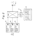
- FIG. 2 is a view more specifically showing the conventional system of Fig. 1.
- the above-mentioned registration area is formed in the memory 15.
- the reading and writing operations with respect to the memory 15 are performed by a central processing unit (CPU) 14.
- CPU central processing unit
- a subscriber (ID is #111) with the telephone set 13 at the right side of the figure as the home position is shown as changing his location to office "Y".
- FIG. 3 is a block diagram showing the principle and construction of the system of the present invention.
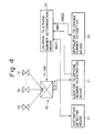
- the automatic personal search telephone apparatus 10 has the above-mentioned location telephone number registration means 11 and also a location telephone number determining means 21 and location information source 22.
- the location telephone number determining means 21 receives as input the first information NB1 read out from the location telephone number registration means 11 and the second information NB2 specifying more accurately the first information NB1, determines the location telephone number NB envisioned as where the call terminating subscriber is currently located, and outputs it to the exchange 12.
- the location information source 22 collects and holds information on the movements of the call terminating subscriber to so as provide the second information NB2.
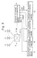
- FIG. 5 is a view showing a second embodiment of the system according to the present invention.
- This second embodiment consists of the above-mentioned first embodiment with the addition of a schedule management means 33.
- This means 33 provides schedule management information NB23 of the call terminating subscriber to the location telephone number determining means 21.
- This schedule management means 33 is provided in offices having schedule management systems which manage the scheduled destinations (conference rooms etc.) corresponding to personal identification numbers of call terminating subscriber and manages the scheduled destinations and telephone numbers thereof of the call terminating subscriber.
- the location telephone number determining means 21 judges that the telephone number of the call terminating subscriber cannot be specified by the location telephone number registration means 11 or the telephone number of the call terminating subscriber cannot be specified by the destination telephone number extracting means 32 which extracts the telephone number based on the location of the call terminating subscriber detected by the destination detecting means 31, the means 21 finds the telephone number by the schedule management means 33.
- Figure 6 is a view showing somewhat more specifically the system according to the present invention and is based on the above-mentioned second embodiment. If based on the first embodiment, the blocks 33 and 43 would be excluded from the figure.
- DB1 the file units forming the data base (DB) are shown by reference numerals 41, 42, 43, and 51.
- the individual data bases in the file units are shown by DB1, DB2, DB3, and DB0. The contents of them are as follows:
- a telephone system constructed in this way has the subscriber telephone sets 13 which registers the personal identification numbers ID in advance in the file units 51 as DBO.
- a personal identification number 1 (ID) input from a subscriber telephone set 13 by a call originating subscriber is received by the electronic exchange 12 and a request for the personal search telephone operation is recognized, the electronic exchange 12 notifies the personal identification number 1 to the location telephone number determining means 21 and requests the desired telephone number.
- the location telephone number determining means 21 uses the personal identification number 1 as a retrieval key and learns the current destination information 2 (NB21) from the current destination information data base DB1 managed through the current destination detecting means 31, for example, an entry/exit management apparatus, obtains the destination telephone number information 3 (NB22), obtains the location telephone number information 4 (NB1) from the location telephone number information data base DBO managed through the location telephone number registration means 11, and thus obtains the telephone number of the location of the call terminating subscriber.
- the location telephone number determining means 21 first compares the current destination information 2 with the telephone number given by the location telephone number information 4 and if they match notifies the location telephone number information 4 to the electronic exchange 12 as the telephone number 6 (NB) which is to be searched.
- the telephone number information 3 corresponding to the current destination information 2 is notified to the electronic exchange 12 as the telephone number 6 which is to be searched.
- the telephone number 5 obtained from the schedule management means 33 is notified to the electronic exchange 12 as the telephone number 6 which is to be searched.
- the predetermined telephone number 4 corresponding to the personal identification number 1 (in general, the key telephone number of the sector to which the call terminating subscriber belongs) is notified to the electronic exchange 12 as the telephone number 6 which is to be searched.
- the electronic exchange 12 connects, using the telephone number 6, the subscriber telephone set 13 at which the personal identification number 1 has input.
- the apparatuses 31, 32, 33, 21, and 11 making up the location telephone number determining means 21 were provided as independent apparatuses, but if the desired information can be managed as a whole, a single apparatus may be provided. Further, two or three apparatuses may be provided, or even more apparatuses provided. Further, these apparatuses may be realized using specialized hardware or using software using a general purpose computer etc. All the apparatuses may be included in the electronic exchange 12. Whatever the case, the principle and effects are all the same. When software is used, the flow chart shown in Figs. 7A, 7B, and 7C may be applied, and when hardware is used, the block construction of the later mentioned Fig. 8 may be applied. Each of these, however, are just examples.
- Figures 7A(7A-1, 7A-2), 7B, and 7C show a flow chart showing an example of the operation of the location telephone number determining means according to the present invention. Near the steps in which the file units are directly referred to, respective file units are illustrated at corresponding steps. The exchange 12 and the subscriber telephone set 13 are also illustrated near the related steps.
- Figure 8 is a view showing an example of the hardware of a logical processing portion of a location information source and a location telephone number determining means according to the present invention. This is an example of the hardware construction of the portion but the file units in Fig. 6 are omitted.
- the group of blocks to the right of a decision logic unit 211 is the portion for reading out data from the corresponding file units (41, 42, 43, and 51). Those blocks which are given reference numerals where the two hundred-place and ten-place digit numbers are the same as reference numerals in Fig. 6 correspond to those functional portions.
- the location telephone number reading unit 111 and the registered telephone number (telephone number of home position of subscribers) reading unit 112 correspond to the location telephone number registration means 11 of Fig. 6,
- the destination information reading unit 311 corresponds to the destination detecting means 31 of Fig. 6, and the destination telephone number reading unit 321 corresponds to the destination telephone number extracting means 32 of Fig. 6.
- the data read out from these reading units are used as the input of the decision logic unit 211.
- the destination telephone number extracting means 32 in both the first embodiment and the second embodiment is a memory which stores, in a form of table for each of the locations, the telephone numbers corresponding to locations of destinations of the call terminating subscribers.
- the means 31 may be a detector, for example, a time clock (time recorder), which produces work attendance/absence information managed using, as a medium, IC cards or other personal cards of the call terminating subscriber used when call terminating subscriber enter or exit a building or room.
- a time clock time recorder
- the means 31 may be a detector, for example, a pass room checker which produces entry/exit information managed using, as a medium, IC cards or other personal cards of call terminating subscriber used when entering or existing a building or room.
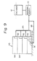
- Figure 9 is a view showing first and second example of a destination detecting means.
- the above-mentioned time recorder (first example) is shown by reference numeral 91 and the above-mentioned pass room checker (second example) by 92.
- reference numeral 10 is an automatic personal search telephone apparatus according to the present invention
- 93 is a building
- 94 is a room
- 95 is a data base.
- the destination detecting means 31 is a password entry device, for example, a 10-key or ID card reader, which receives as input personal password information on terminal equipment which a call terminating subscriber can use when the call terminating subscriber uses terminal equipment. If the terminal equipment is digital telephone equipment, it may be pushbutton. In general, the terminal equipment is a personal computer or work station.
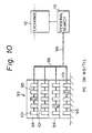
- FIG 10 is a view showing a third example of a destination detecting means.
- the above-mentioned terminal equipment (TE) is shown by reference numeral 101.
- This has a password entry device attached (third example).
- the destination detecting means 31 may be comprised of a personal, portable transmitter carried by call terminating subscriber, the personal identification number information corresponding to the call terminating subscriber being transmitted by radio waves from the transmitters. The radio waves are received by receivers in the rooms.
- Figure 11 is a view showing the fourth example of a destination detecting means.
- the above-mentioned transmitter and receiver (fourth example) are shown respectively by reference numerals 111 and 112.
- FIG. 12 is a view showing a first example of the constitution of the automatic personal search telephone system according to the present invention.
- the automatic personal search telephone apparatus 10 according to the present invention is formed integrally inside the exchange 12.
- the automatic personal search telephone apparatus 10 is shown assembled in the central processing unit (CPU) 14 in the exchange 12.
- Reference numeral 16 is a memory (MEM) which cooperates with the CPU 14.
- the CPU 1 is the central processing unit serving as the center of a work attendance/absence management system.
- the work attendance/absence information S 1 is input and the predetermined processing is performed, then the data of the call terminating subscribers is supplied to the CPU 14.
- the CPU 2 is a central processing unit serving as the center of, for example, a building management system.
- the information S 2 in the building for the call terminating subscriber is input and the predetermined processing performed, then the data on the call terminating subscribers is supplied to the CPU 14.
- FIG. 13 is a view showing a second example of the constitution of the automatic personal search telephone system according to the present invention.
- the automatic personal search telephone apparatus 10 according to the present invention is provided separately outside the exchange 12.
- the central processing unit (CPU 0 ) serving as the center of the external automatic personal search telephone apparatus 10 is shown cooperating with the CPU 14 in the exchange 12.
- the CPU 14 and the CPU 0 are connected by a TCSI.
- TCSI stands for a telecommunication and computer service interface.
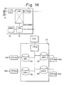
- the CPU 1 , CPU 2 , S 1 , and S 2 are as explained in Fig. 12. Therefore, the CPU 14 obtains the destination information of the call terminating subscriber from the external CPU 0 and controls the network NW using this as control information.
- the data bases DB0 to DB3 are managed by the central processing units CPU 00 to CPU 30 .
- the CPU 00 to CPU 30 collect various types of information S 00 to S 30 .
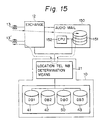
- FIG. 15 is a view showing a third example of the constitution of the automatic personal search telephone system according to the present invention.
- the characteristic feature of the third example is that the call originating subscriber can register voice mail from the subscriber telephone set 13 and that voice mail can be transmitted to the subscriber telephone set 13' at the destination of the call terminating subscriber.
- a well known voice mail apparatus 150 is connected to the exchange 12.
- the apparatus 150 is a file 151 which records voice mail.
- the location telephone number determining means 21 deduces the location of the call terminating subscriber at that time and sends the voice mail to the subscriber telephone set 13' nearest to the call terminating subscriber.
- the location of the call terminating subscriber is deduced by reference to the various types of data bases (DB).
- the operation is as follows.
- the exchange 12 receives from the call originating subscriber (13) the personal identification number ID as an originating call.
- the exchange 12 when judging by that call that it must perform the voice mail service, records the voice mail for the call terminating subscriber in the file corresponding to the ID.
- Figure 16 is a view showing the specific image of the automatic personal search telephone system according to the present invention and makes much clearer the difference from the conventional system (Fig. 2).
- the memory area of the location telephone number registration means 11, the memory area of the destination detecting means 31, the memory area of the destination telephone number extracting means 32, and the memory area of the schedule management means 33 are shared.
- the memory area 11 is formed a table of pairs of ID's and telephone numbers
- in the memory area 31 is formed a table showing if a call terminating subscriber corresponding to an ID is in a room (room 1, room 2, room 3, ...)
- in memory area 32 is formed a table comprised of pairs of offices (X, Y, Z...) and telephone numbers used in the same.
- the star symbols show key telephone numbers.
- the memory area 33 is formed a schedule table of the call terminating subscriber corresponding to the ID.
Landscapes
- Engineering & Computer Science (AREA)
- Signal Processing (AREA)
- Physics & Mathematics (AREA)
- Astronomy & Astrophysics (AREA)
- General Physics & Mathematics (AREA)
- Computer Networks & Wireless Communication (AREA)
- Telephonic Communication Services (AREA)
- Mobile Radio Communication Systems (AREA)
Claims (15)
- Automatisches Personensuchtelefonsystem, umfassend:a) eine Vermittlungsstelle (12), die mit einer Vielzahl von Teilnehmertelefongeräten (13) verbunden ist; undb) eine automatische Personensuchtelefonvorrichtung (10, 21, 22, 11, Fig. 3), die mit der Vermittlungsstelle (12) verbunden ist und umfaßt:gekennzeichnet durch
b1) eine Aufenthaltsort-Telefonnummern-Registriereinrichtung (11), um beim Empfang einer Personenidentifikationsnummer (ID) eines Anrufendteilnehmers von dem Teilnehmertelefongerät (13) eines Anrufursprungsteilnehmers aus einem Registrierbereich (51), welcher der Personenidentifikationsnummer (ID) entspricht, eine erste Telefonnummerninformation (NB1) an einem gegenwärtigen Aufenthaltsort eines Anrufendteilnehmers auszulesen;b2) eine Aufenthaltsort-Informationsquelle (22) zum Sammeln und Halten von Information bezüglich der Bewegungen des Anrufendteilnehmers und des Zielorts des Anrufendteilnehmers zum Bereitstellen einer zweiten Telefonnummerninformation (NB2), die dem entspricht;b3) eine Aufenthaltsort-Telefonnummern-Bestimmungseinrichtung (21)b31) zum Empfangen der ersten Telefonnummerninformation (NB, NB1), die aus der Aufenthaltsort-Telefonnummern-Registriereinrichtung (11) ausgelesen wird und der zweiten Telefonnummerninformation (NB2), die die erste Telefonnummerninformation (NB1) genauer spezifiziert;b32) zum Bestimmen einer Telefonnummer (NB) eines Aufenthaltsorts, von dem angenommen wird, daß er der Aufenthaltsort des Anrufendteilnehmers ist;- wobei bestimmt wird, daß die Telefonnummer (NB) die erste Telefonnummerninformation (NB, NB1) ist, die aus der Aufenthaltsort-Telefonnummern-Registriereinrichtung (11) ausgelesen wird, wenn die erste und zweite TelefonnummernInformation (NB1; NB2) identisch sind; und- wobei bestimmt wird, daß die Telefonnummer (NB) die zweite Telefonnummerninformation (NB2) ist, die von der Aufenthaltsort-Informationsquelle (22) bereitgestellt wird, wenn die erste und zweite Telefonnummerninformation (NB1; NB2) nicht identisch sind, undb33) zum Ausgeben der bestimmten Telefonnummer (NB) des Aufenthaltsorts an die Vermittlungsstelle (12) als die Telefonnummer (NB) eines gegenwärtigen Aufenthaltsorts des Anrufendteilnehmers. - System nach Anspruch 1,
dadurch gekennzeichnet, daß
die Aufenthaltsort-Informationsquelle (12) wenigstens eine Art von Information der Zielort-Erfassungsinformaton (NB21), von vorher bereitgestellter Zielort-Telefonnummern-Extraktionsinformation (NB22) und Planungsverwaltungsinformation (NB23) für den Anrufendteilnehmer sammelt und hält. - System nach Anspruch 2,
dadurch gekennzeichnet, daß
die Aufenthaltsort-Telefonnummern-Registriereinrichtung (11), die Aufenthaltsort-Telefonnummern-Bestimmungseinrichtung (21) und die Aufenthaltsort-Informationsquelle (22) in die Vermittlungsstelle (12) eingebaut sind. - System nach Anspruch 2,
dadurch gekennzeichnet, daß
die Aufenthaltsort-Telefonnummern-Registiereinrichtung (11), die Aufenthaltsort-Telefonnummern-Bestimmungseinrichtung (21) und die Aufenthaltsort-Informationsquelle (22) getrennt von und ausserhalb der Vermittlungsstelle (12) vorgesehen sind. - System nach Anspruch 1,
dadurch gekennzeichnet, daß
die Aufenthaltsort-Informationsquelle (22) umfaßt:a) eine Aufenthaltsort-Erfassungseinrichtung (31), die einen gegenwärtigen Aufenthaltsort des Anrufendteilnehmers erfaßt;b) eine Aufenthaltsort-Telefnnummern-Extraktionseinrichtung (32), die Telefonnummern von entsprechenden Zielorten für jeden Zielort des Anrufendteilnehmers speichert; und wobeic) die Aufenthaltsort-Telefonnummern-Bestimmungseinrichtung (21) ausgelegt ist zum Spezifizieren der gegenwärtigen Telefonnummer des Anrufendteilnehmers, die durch eine Telefonummer von der Aufenthaltsort-Telefonnummern-Registriereinrichtung gegeben wird, oder einer Telefonnummer, die von der Zielort-Telefonnummern-Extraktionseinrichtung gegeben wird, die als Eingang den von der Zielort-Erfassungseinrichtung erfaßten Zielort des Anrufendteilnehmers empfängt. - System nach Anspruch 5,
gekennzeichnet durch:eine Planungsverwaltungseinrichtung (33), die Planungsverwaltungsinformation des Anrufendteilnehmers an der Aufenthaltsort-Telefonnummern-Bestimmungseinrichtung (21) bereitstellt; wobeidie Aufenthaltsort-Telefonnummern-Bestimmungseinrichtung (21) ausgelegt ist zum Spezifizieren der gegenwärtigen Telefonnummer des Anrufendteilnehmers auf Grundlage eines geplanten Zielorts des Anrufendteilnehmers, der von der Planungsverwaltungseinrichtung (33) gegeben wird, wenn eine gegenwärtige Telefonnummer des Anrufendteilnehmers durch eine Telefonnummer von der Aufenthaltsort-Telefonnummern-Registriereinrichtung (11) nicht spezifiziert werden kann, oder einer Telefonnummer, die von der Aufenthaltsort-Telefonnummern-Extraktionseinrichtung (32) gegeben wird, die als Eingang den von der Zielort-Erfassungseinrichtung (31) erfaßten Zielort des Anrufendteilnehmers empfängt. - System nach Anspruch 5,
adurch gekennzeichnet, daß
die Zielort-Telefonnummern-Extraktionseinrichtung (32) ein Speicher ist, der als eine Tabelle, für jede Position eines Zielorts des Anrufendteilnehmers, Telefonnummern entsprechend zu der Position speichert. - System nach Anspruch 5,
adurch gekennzeichnet, daß
die Zielort-Erfassungseinrichtung (31) ein Detektor ist, der Arbeitsanwesenheits/-Abwesenheits-Information erzeugt, die unter Verwendung einer IC-Karte oder einer anderen Personenkarte von Anrufzielteilnehmern als ein Medium, die verwendet werden, wenn die Anrufendteilnehmer ein Gebäude oder einen Raum betreten oder verlassen, verwaltet wird. - System nach Anspruch 5,
dadurch gekennzeichnet, daß
die Zielort-Erfassungseinrichtung (31) ein Detektor ist, der Eintritts/Austrittsinformation erzeugt, die unter Verwendung einer IC-Karte oder einer anderen Personenkarte von Anrufendteilnehmern als ein Medium, die verwendet werden, wenn die Anrufendteilnehmer ein Gebäude oder einen Raum betreten oder verlassen, verwaltet wird. - System nach Anspruch 5,
dadurch gekennzeichnet, daß
die Zielort-Erfassungseinrichtung (31) eine Kennworteingabeeinrichtung ist, zur Eingabe einer Personenkennwortinformation an einem Stationsgerät, welches Anrufendteilnehmer verwenden können, wenn die Anrufendteilnehmer das Stationsgerät verwenden. - System nach Anspruch 5,
dadurch gekennzeichnet, daß
die Zielort-Erfassungseinrichtung (31) Empfänger (112) und persönliche tragbare Sender (111) umfasst, die von Anrufendteilnehmern getragen werden, wobei Personenidentifikationsnummerninformation, die den Anrufendteilnehmern entsprechen, durch Funkwellen von den Sendern übertragen wird und dies von dem Empfänger empfangen wird. - System nach Anspruch 1,
dadurch gekennzeichnet, daß
die automatische Personensuchtelefonvorrichtung (10) in die Vermittlungstelle (12) eingebaut ist. - System nach Anspruch 1,
dadurch gekennzeichnet, daß
die automatische Personensuchtelefonvorrichtung (10) getrennt von und ausserhalb von der Vermittlungstelle (12) vorgesehen ist. - System nach Anspruch 1,
dadurch gekennzeichnet, daß
ferner eine Voicemail Vorrichtung (150) vorgesehen ist, die mit der Vermittlungsstelle (12) und der automatischen Pesonensuchtelefonvorrichtung (10) verbunden ist, und daß, wenn die Vermittlungstelle (12) von einem Anrufursprungsteilnehmer Voicemail empfängt, die an den durch die Personenidentifikationsnummer (ID) spezifizierten Anrufendteilnehmer adressiert ist, die Voicemail einmal in der Voicemail-Vorrichtung registriert wird und ferner die Voicemail-Vorrichtung durch Verwendung der Personenidentifikationsnummer (ID) auf die automatische Personensuchtelefonvorrichtung zugreift und die Voicemail durch die Vermittlungstelle an den Anrufendteilnehmer tansferiert. - System nach Anspruch 14,
dadurch gekennzeichnet, daß
wenn eine Zeit für eine Zustellung der Voicemail bestimmt wird, die Voicemail Vorrichtung (150) auf die automatische Personensuchtelefonvorrichtung zugreift, wenn die bestimmte Zeit gekommen ist.
Applications Claiming Priority (2)
| Application Number | Priority Date | Filing Date | Title |
|---|---|---|---|
| JP2068155A JPH03270453A (ja) | 1990-03-20 | 1990-03-20 | 自動追い掛け電話装置 |
| JP68155/90 | 1990-03-20 |
Publications (3)
| Publication Number | Publication Date |
|---|---|
| EP0448076A2 EP0448076A2 (de) | 1991-09-25 |
| EP0448076A3 EP0448076A3 (en) | 1993-04-14 |
| EP0448076B1 true EP0448076B1 (de) | 1997-07-16 |
Family
ID=13365576
Family Applications (1)
| Application Number | Title | Priority Date | Filing Date |
|---|---|---|---|
| EP91104338A Expired - Lifetime EP0448076B1 (de) | 1990-03-20 | 1991-03-20 | Automatisches Personensuchfernsprechsystem |
Country Status (6)
| Country | Link |
|---|---|
| US (1) | US5414759A (de) |
| EP (1) | EP0448076B1 (de) |
| JP (1) | JPH03270453A (de) |
| AU (1) | AU627990B2 (de) |
| CA (1) | CA2038476C (de) |
| DE (1) | DE69126806T2 (de) |
Families Citing this family (37)
| Publication number | Priority date | Publication date | Assignee | Title |
|---|---|---|---|---|
| JP3017872B2 (ja) * | 1992-01-21 | 2000-03-13 | 株式会社東芝 | 電子交換システムとその電子交換機並びに内線番号変更プログラムを記憶した記憶媒体 |
| US5430791A (en) * | 1993-02-26 | 1995-07-04 | At&T Corp. | Technique for administering personal telephone numbers |
| JPH07283875A (ja) * | 1994-04-06 | 1995-10-27 | Fujitsu Ltd | 対地群管理を用いた交換制御方式 |
| DE4420462A1 (de) * | 1994-06-13 | 1995-12-14 | Sel Alcatel Ag | Verfahren zur Auswahl eines von mindestens zwei Fernmeldeendgeräten und Fernmeldeendgerät dafür |
| JPH08256216A (ja) * | 1995-03-16 | 1996-10-01 | Fujitsu Ltd | 着呼転送方式及び電子メール転送方式 |
| US5845207A (en) * | 1996-05-09 | 1998-12-01 | At&T Wirless Services, Inc. | Service transfer to a wireless telephone |
| US6160881A (en) * | 1996-09-19 | 2000-12-12 | Siemens Information And Communication Networks, Inc. | System and method for integrating electronic entry systems with telecommunication systems |
| US5802147A (en) * | 1996-09-19 | 1998-09-01 | Siemens Business Communication Systems, Inc. | System and method for notifying a user of awaiting messages |
| US6167117A (en) * | 1996-10-07 | 2000-12-26 | Nortel Networks Limited | Voice-dialing system using model of calling behavior |
| US5917891A (en) * | 1996-10-07 | 1999-06-29 | Northern Telecom, Limited | Voice-dialing system using adaptive model of calling behavior |
| US5905789A (en) * | 1996-10-07 | 1999-05-18 | Northern Telecom Limited | Call-forwarding system using adaptive model of user behavior |
| US5912949A (en) * | 1996-11-05 | 1999-06-15 | Northern Telecom Limited | Voice-dialing system using both spoken names and initials in recognition |
| AU5075698A (en) * | 1996-11-12 | 1998-06-03 | Telefonaktiebolaget Lm Ericsson (Publ) | Device for routing information updates |
| JP3760581B2 (ja) * | 1997-07-28 | 2006-03-29 | 富士通株式会社 | 通信相手情報検索装置及びそれを用いた通信支援システム |
| US5991377A (en) * | 1997-08-11 | 1999-11-23 | Bellsouth Intellectual Property Corporation | System and method for manipulating data fields in a call structure for synchronizing billing information and retaining original calling party information |
| JP3298484B2 (ja) | 1997-12-24 | 2002-07-02 | カシオ計算機株式会社 | 情報送信装置 |
| US6807258B1 (en) | 1998-08-25 | 2004-10-19 | Bellsouth Intellectual Property Corporation | Method and system for billing remote calls as if made from a primary line |
| US8644475B1 (en) | 2001-10-16 | 2014-02-04 | Rockstar Consortium Us Lp | Telephony usage derived presence information |
| US7299286B2 (en) * | 2001-12-27 | 2007-11-20 | Nortel Networks Limited | Personal user agent |
| US20030135624A1 (en) * | 2001-12-27 | 2003-07-17 | Mckinnon Steve J. | Dynamic presence management |
| US6658095B1 (en) | 2002-03-19 | 2003-12-02 | Nortel Networks Limited | Customized presence information delivery |
| US7227937B1 (en) | 2002-03-19 | 2007-06-05 | Nortel Networks Limited | Monitoring natural interaction for presence detection |
| US7139797B1 (en) | 2002-04-10 | 2006-11-21 | Nortel Networks Limited | Presence information based on media activity |
| US7035923B1 (en) | 2002-04-10 | 2006-04-25 | Nortel Networks Limited | Presence information specifying communication preferences |
| US7212837B1 (en) * | 2002-05-24 | 2007-05-01 | Airespace, Inc. | Method and system for hierarchical processing of protocol information in a wireless LAN |
| US8392609B2 (en) | 2002-09-17 | 2013-03-05 | Apple Inc. | Proximity detection for media proxies |
| US20040059781A1 (en) * | 2002-09-19 | 2004-03-25 | Nortel Networks Limited | Dynamic presence indicators |
| US7555108B2 (en) * | 2002-10-01 | 2009-06-30 | Nortel Networks Limited | Presence information for telephony users |
| US20040122901A1 (en) * | 2002-12-20 | 2004-06-24 | Nortel Networks Limited | Providing computer presence information to an integrated presence system |
| US7257218B2 (en) * | 2002-12-30 | 2007-08-14 | Nortel Networks Limited | Presence enabled queue management |
| US7711810B2 (en) * | 2003-01-03 | 2010-05-04 | Nortel Networks Limited | Distributed services based on presence technology |
| US9118574B1 (en) | 2003-11-26 | 2015-08-25 | RPX Clearinghouse, LLC | Presence reporting using wireless messaging |
| US8229454B1 (en) | 2004-03-22 | 2012-07-24 | Avaya Inc. | Personal location information management |
| US8306207B2 (en) * | 2005-09-21 | 2012-11-06 | International Business Machines Corporation | Method and apparatus for forwarding incoming telecommunication calls according to receiver position |
| US20070088839A1 (en) * | 2005-10-19 | 2007-04-19 | Nortel Networks Limited | Local time related presence automation and session control |
| US8355363B2 (en) * | 2006-01-20 | 2013-01-15 | Cisco Technology, Inc. | Intelligent association of nodes with PAN coordinator |
| JP7331167B2 (ja) * | 2022-01-31 | 2023-08-22 | キヤノン株式会社 | 通知システム、通知方法、及びプログラム |
Family Cites Families (16)
| Publication number | Priority date | Publication date | Assignee | Title |
|---|---|---|---|---|
| US3728486A (en) * | 1971-08-26 | 1973-04-17 | C Kraus | Voicegram service |
| US4313035A (en) * | 1980-01-18 | 1982-01-26 | Bell Telephone Laboratories, Incorporated | Method of providing person locator service |
| US4436962A (en) * | 1982-03-30 | 1984-03-13 | Bell Telephone Laboratories, Incorporated | Call coverage arrangement |
| US4476349A (en) * | 1982-03-30 | 1984-10-09 | At&T Bell Laboratories | Call message service |
| US4436963A (en) * | 1982-03-30 | 1984-03-13 | Bell Telephone Laboratories, Incorporated | Implied principal addressing in a call coverage arrangement |
| US4649385A (en) * | 1982-08-13 | 1987-03-10 | Teloc R & D Ltd. | Electronic locating system for persons receiving telephone calls |
| JPS6010470A (ja) * | 1983-06-29 | 1985-01-19 | Nec Corp | 磁気デイスク装置 |
| JPS60109363A (ja) * | 1983-11-17 | 1985-06-14 | Fujitsu Ltd | 呼処理制御方式 |
| JPS60170341A (ja) * | 1984-02-14 | 1985-09-03 | Nec Corp | 交換方式 |
| US4670900A (en) * | 1985-04-17 | 1987-06-02 | Waldman Herbert H | Single line telephone call forwarding device |
| US4752951A (en) * | 1985-12-23 | 1988-06-21 | Konneker Lloyd K | Method of providing location dependent person locator service |
| US4852156A (en) * | 1986-10-13 | 1989-07-25 | Casio Computer Co., Ltd. | Private telephone system using a personal code number to access the telephone nearest to the code number holder |
| US4899373A (en) * | 1986-11-28 | 1990-02-06 | American Telephone And Telegraph Company At&T Bell Laboratories | Method and apparatus for providing personalized telephone subscriber features at remote locations |
| JP2577768B2 (ja) * | 1988-03-29 | 1997-02-05 | 株式会社日立製作所 | ホテル用構内交換機におけるゲストロケーション表示方法 |
| JPH01279665A (ja) * | 1988-05-06 | 1989-11-09 | Hitachi Ltd | 不在転送方式 |
| DE3826025C2 (de) * | 1988-07-30 | 2001-06-21 | Tenovis Gmbh & Co Kg | Verfahren, mit dem Eigenschaften einer Kommunikations-Vermittlungsanlage verändert werden können |
-
1990
- 1990-03-20 JP JP2068155A patent/JPH03270453A/ja active Pending
-
1991
- 1991-03-18 CA CA002038476A patent/CA2038476C/en not_active Expired - Fee Related
- 1991-03-19 AU AU73557/91A patent/AU627990B2/en not_active Ceased
- 1991-03-20 DE DE69126806T patent/DE69126806T2/de not_active Expired - Fee Related
- 1991-03-20 EP EP91104338A patent/EP0448076B1/de not_active Expired - Lifetime
-
1993
- 1993-09-20 US US08/124,376 patent/US5414759A/en not_active Expired - Fee Related
Also Published As
| Publication number | Publication date |
|---|---|
| JPH03270453A (ja) | 1991-12-02 |
| AU627990B2 (en) | 1992-09-03 |
| AU7355791A (en) | 1991-09-26 |
| EP0448076A3 (en) | 1993-04-14 |
| DE69126806D1 (de) | 1997-08-21 |
| US5414759A (en) | 1995-05-09 |
| CA2038476C (en) | 1995-02-07 |
| EP0448076A2 (de) | 1991-09-25 |
| DE69126806T2 (de) | 1997-12-11 |
Similar Documents
| Publication | Publication Date | Title |
|---|---|---|
| US5414759A (en) | Automatic personal search telephone system | |
| US4661974A (en) | Automatic route selection of a private telephone network path on the basis of a public telephone network number | |
| US5761620A (en) | Private network system and method of transferring an incoming call | |
| US4899373A (en) | Method and apparatus for providing personalized telephone subscriber features at remote locations | |
| EP0410657B1 (de) | Gerät und Verfahren zur Verarbeitung eines Fernsprechanrufs mit kostenloser Nummer | |
| US7292865B2 (en) | Location visit detail services for wireless devices | |
| US6601068B1 (en) | Home location register management system and database management method in mobile radio communication system | |
| US5067154A (en) | Terminal management method and apparatus | |
| EP0896776A1 (de) | Leitweglenkung | |
| US4837807A (en) | Station to station message arrangement | |
| US5533113A (en) | Automatic position managing system | |
| KR19980016076A (ko) | 통신망을 통한 개인일정 관리장치 및 관리방법 | |
| US5276441A (en) | Communication charge manageable digital communication unit and a method of managing communication charge | |
| US5905944A (en) | Secure communication of access information | |
| WO2001031965A1 (en) | Multiple source location method | |
| US5448617A (en) | Method of processing intelligent network service call with DTMF subscriber signalling in electronic switching system for toll/tandem | |
| CA2020574C (en) | Communication charge manageable digital communication unit and a method of managing communication charge | |
| US6393009B1 (en) | Method for managing trunk status of a CDMA mobile communication exchange | |
| US5642403A (en) | Portable telephone set tracking connection system in mobile communication network | |
| KR960011707B1 (ko) | 과금용 자기테이프(mt)를 이용한 전전자 교환기의 트래픽 데이타 분석방법 | |
| US6611588B1 (en) | Support for change of numbers | |
| JP3443015B2 (ja) | 電話番号情報記録方法、装置、及び記録媒体 | |
| JPH0388554A (ja) | 勤務管理システム | |
| JPH0637898A (ja) | 構内交換機 | |
| KR20000025628A (ko) | 평생 전화번호를 이용한 전자메일 송수신 장치 및 그 방법 |
Legal Events
| Date | Code | Title | Description |
|---|---|---|---|
| PUAI | Public reference made under article 153(3) epc to a published international application that has entered the european phase |
Free format text: ORIGINAL CODE: 0009012 |
|
| AK | Designated contracting states |
Kind code of ref document: A2 Designated state(s): DE FR GB |
|
| RIN1 | Information on inventor provided before grant (corrected) |
Inventor name: YAMAMOTO, SHIGENOBU Inventor name: ISHIKURI, HIROAKI |
|
| PUAL | Search report despatched |
Free format text: ORIGINAL CODE: 0009013 |
|
| AK | Designated contracting states |
Kind code of ref document: A3 Designated state(s): DE FR GB |
|
| 17P | Request for examination filed |
Effective date: 19930820 |
|
| 17Q | First examination report despatched |
Effective date: 19951023 |
|
| GRAG | Despatch of communication of intention to grant |
Free format text: ORIGINAL CODE: EPIDOS AGRA |
|
| GRAH | Despatch of communication of intention to grant a patent |
Free format text: ORIGINAL CODE: EPIDOS IGRA |
|
| GRAH | Despatch of communication of intention to grant a patent |
Free format text: ORIGINAL CODE: EPIDOS IGRA |
|
| GRAA | (expected) grant |
Free format text: ORIGINAL CODE: 0009210 |
|
| AK | Designated contracting states |
Kind code of ref document: B1 Designated state(s): DE FR GB |
|
| REF | Corresponds to: |
Ref document number: 69126806 Country of ref document: DE Date of ref document: 19970821 |
|
| ET | Fr: translation filed | ||
| PLBE | No opposition filed within time limit |
Free format text: ORIGINAL CODE: 0009261 |
|
| STAA | Information on the status of an ep patent application or granted ep patent |
Free format text: STATUS: NO OPPOSITION FILED WITHIN TIME LIMIT |
|
| 26N | No opposition filed | ||
| PGFP | Annual fee paid to national office [announced via postgrant information from national office to epo] |
Ref country code: FR Payment date: 20000310 Year of fee payment: 10 |
|
| PGFP | Annual fee paid to national office [announced via postgrant information from national office to epo] |
Ref country code: GB Payment date: 20000315 Year of fee payment: 10 |
|
| PGFP | Annual fee paid to national office [announced via postgrant information from national office to epo] |
Ref country code: DE Payment date: 20000318 Year of fee payment: 10 |
|
| PG25 | Lapsed in a contracting state [announced via postgrant information from national office to epo] |
Ref country code: GB Free format text: LAPSE BECAUSE OF NON-PAYMENT OF DUE FEES Effective date: 20010320 |
|
| GBPC | Gb: european patent ceased through non-payment of renewal fee |
Effective date: 20010320 |
|
| PG25 | Lapsed in a contracting state [announced via postgrant information from national office to epo] |
Ref country code: FR Free format text: LAPSE BECAUSE OF NON-PAYMENT OF DUE FEES Effective date: 20011130 |
|
| REG | Reference to a national code |
Ref country code: FR Ref legal event code: ST |
|
| PG25 | Lapsed in a contracting state [announced via postgrant information from national office to epo] |
Ref country code: DE Free format text: LAPSE BECAUSE OF NON-PAYMENT OF DUE FEES Effective date: 20020101 |