EP0448081B1 - Vorrichtung zum Zuführen eines Deckblatts - Google Patents
Vorrichtung zum Zuführen eines Deckblatts Download PDFInfo
- Publication number
- EP0448081B1 EP0448081B1 EP91104344A EP91104344A EP0448081B1 EP 0448081 B1 EP0448081 B1 EP 0448081B1 EP 91104344 A EP91104344 A EP 91104344A EP 91104344 A EP91104344 A EP 91104344A EP 0448081 B1 EP0448081 B1 EP 0448081B1
- Authority
- EP
- European Patent Office
- Prior art keywords
- feeding
- top sheet
- air flow
- air flows
- widthwise direction
- Prior art date
- Legal status (The legal status is an assumption and is not a legal conclusion. Google has not performed a legal analysis and makes no representation as to the accuracy of the status listed.)
- Expired - Lifetime
Links
- 238000011144 upstream manufacturing Methods 0.000 claims description 9
- 238000002347 injection Methods 0.000 description 7
- 239000007924 injection Substances 0.000 description 7
- 238000000926 separation method Methods 0.000 description 7
- 230000002349 favourable effect Effects 0.000 description 6
- 238000000034 method Methods 0.000 description 5
- 239000000203 mixture Substances 0.000 description 5
- 238000012546 transfer Methods 0.000 description 4
- 238000007664 blowing Methods 0.000 description 2
- 239000000470 constituent Substances 0.000 description 2
- 230000003134 recirculating effect Effects 0.000 description 2
- 238000013459 approach Methods 0.000 description 1
- 210000000078 claw Anatomy 0.000 description 1
- 230000002950 deficient Effects 0.000 description 1
- 238000011161 development Methods 0.000 description 1
- 230000018109 developmental process Effects 0.000 description 1
- 238000010586 diagram Methods 0.000 description 1
- 238000009792 diffusion process Methods 0.000 description 1
- 238000006073 displacement reaction Methods 0.000 description 1
- 230000000694 effects Effects 0.000 description 1
- 230000003028 elevating effect Effects 0.000 description 1
- 238000003780 insertion Methods 0.000 description 1
- 230000037431 insertion Effects 0.000 description 1
- 230000003287 optical effect Effects 0.000 description 1
- 230000035515 penetration Effects 0.000 description 1
Images








Classifications
-
- B—PERFORMING OPERATIONS; TRANSPORTING
- B65—CONVEYING; PACKING; STORING; HANDLING THIN OR FILAMENTARY MATERIAL
- B65H—HANDLING THIN OR FILAMENTARY MATERIAL, e.g. SHEETS, WEBS, CABLES
- B65H3/00—Separating articles from piles
- B65H3/46—Supplementary devices or measures to assist separation or prevent double feed
- B65H3/48—Air blast acting on edges of, or under, articles
Definitions
- the present invention relates to a top sheet feeding apparatus in accordance with the precharacterising part of the independent claim 1.
- a top sheet feeding apparatus is known from EP-A-0222588.
- a sheet feeder is used, such as the feeding apparatus of documents and the feeding apparatus of separating and feeding the stacked recording sheets one by one.
- an apparatus for separating and feeding stacked recording papers is employed. In such paper feeding device, it is necessary to separate the stacked sheets one by one, and various separating methods are known, such as the air flow separating method, separating claw method, and method for separating sheets by using a roller rotating in a reverse direction of sheet feeding direction.
- the sheet feeding apparatus is disclosed in the Japanese Laid-open Patent No. 58-78932, and a similar structure is found in the United States Patent No. 3,198,514 or the Japanese Patent Publication No. 55-19859.
- the structure is shown in Fig. 1, a side view, and in Fig. 2, a plan view.
- This composition is, for example in a copying machine of RDH method, a paper feeding 1 for feeding by separating the stacked recording papers one by one.
- the paper feeder 1 is provided with a support tray 3 on which recording papers 2 are stacked up.
- a notch 4 is formed, and a feed belt 7 stretched on a pair of rotating rollers 5, 6 disposed beneath the support tray 3 and having many penetration holes formed is exposed at this notch 4.
- an air intake duct 8 opposite to the notch 4 across the feed belt 7, and the recording paper 2 on the support tray 3 is attracted by vacuum to the feed belt 7, and is fed in the feeding direction A1 by running and driving of the feed belt 7.
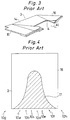
- the support tray 3 has a base part 15 in an extended shape from the downstream side to the upstream side of the feeding direction A1, and a side wing parts 15, 16 formed obliquely upward from the both sides of the widthwise direction of the base part 14, as shown in Fig. 3.
- the air injection duct 9 and support tray 3 in this prior art are arranged as shown in Fig. 1, and the air stream in a flat shape is concentrated near the middle position in the widthwise direction of the support tray 3 by the nozzles 10a to 10f. This state of distribution of air stream by the air injection duct 9 is indicated in the shaded area in Fig. 4.
- This prior art is capable of separating the recording papers 2 favorable as far as the size of the recording papers 2 is relatively small or the weight is relatively large.
- the recording paper of large size or small weight not only the lowermost recording paper but also plural recording papers are deformed with a relatively large deflection, in a recess 19 formed by the base part 15 and side wing parts 15, 16 of the support tray 3, in a shape corresponding to the pattern of the recess, and the gap for entry of air stream is hardly formed among the recording papers, and separation of recording papers may be sometimes unsuccessful.
- the top sheet feeder as known from EP-A-0222588 and corresponding to the precharacterising part of claim 1 comprises one centrally located projection, named corrugation rail which is attached or molded to the underside of the vacuum attraction box or plenum and causes sheets acquired by the vacuum attraction box to bend during the corrugation so that if a second sheet is still sticking to the sheet having been acquired by the vacuum plenum, the corrugation will cause the second sheet to fall back into the paper tray.
- corrugation rail which is attached or molded to the underside of the vacuum attraction box or plenum and causes sheets acquired by the vacuum attraction box to bend during the corrugation so that if a second sheet is still sticking to the sheet having been acquired by the vacuum plenum, the corrugation will cause the second sheet to fall back into the paper tray.
- EP-A-0446889 is a Prior Art Document according to Article 54 (3) and (4) EPC however, the features of the characterising part of the present independent claim 1 are not described in the Japanese Priority Document JP6220590 having the filing date of 13 March, 1990.
- the latter priority document of EP-A0446889 discloses protrusions 306 such as shown in the Figs. 52, 53 and 55 of EP-A0446889 provided in feeding means disposed below the stacked sheets.
- the feeding means is disposed above the sheets stacked up on the laying plate, and this feeding means deforms the top sheet of the stacked-up sheets to be fed, at least at the end part of the feeding direction downstream side of the top sheet, that is, at the front end part, at plural positions in the widthwise direction, partly upward by a negative pressure in, for example, a corrugated form, and feeds the top sheet in such deformed state by attracting in vacuum to the feeding surface, while air flows are injected by the air flow forming means toward the deformed parts from the feeding direction downstream side.
- the top sheet is deformed as stated above, while the other sheets are nearly flat, not attracted in vacuum to the feeding surface.
- the air flow is blown into the part partly deformed upward of the top sheet by negative pressure, and this air flow is synthesized, for example, by the outward air in the widthwise direction and the parallel air in the feeding direction, or formed by only the outward air in the widthwise direction or only the parallel air In the feeding direction, thereby blowing air flow into the gap between the stop sheet and the second and subsequent sheets, and therefore not only sheets of small size, that is, light weight may be fed one by one, but also sheets of large size, that is, heavy weight may be also separated vertically and fed one by one securely, so that sheets in a wide variety of sizes can be securely fed one by one.
- the feeding means has plural feeding stretch belts disposed at mutual intervals in the widthwise direction, and these belts possess multiple air passage holes, and the top sheet is attracted in vacuum to the feeding surface which is a nearly horizontal lower stretching part of each belt.
- the belt is rotated and driven by driving means, and the top sheet attracted in vacuum to the lower stretching part is fed from the feeding direction upstream side toward the downstream side, and a vacuum attraction box is disposed immediately above this lower stretching part, and hence air is taken in from the mutual gaps of the adjacent belts as well as the multiple air passage holes in the belts, so that the sheet is attracted In vacuum to the lower stretching part.
- the sheet is deformed in an upward deflection with roundness upward between the mutual interval of belts.
- the remaining sheets are nearly flat. Therefore, an air flow may be blown into the space formed between the top sheet and the remaining sheets, and the top sheet may be securely separated from the other sheets.
- the protrusions projecting downward from the feeding surface are disposed at the fixed position at plural interval positions between mutual lower stretching parts of adjacent belts, and air flows are injected obliquely toward the protrusions. Therefore, the top sheet attracted in vacuum to the lower stretching part of the belt which is the feeding surface of the feeding means is largely deformed along the protrusions, while the remaining sheets are almost flat. Hence, by injecting and blowing air flow into the space between the top sheet and the remaining sheets, the sheets may be separated easily.
- This air flow is oriented to be directed outward in the widthwise direction from the central side in the widthwise direction to each protrusion, or oriented to be parallel to the feeding direction, or the air directed outward in the widthwise direction and the air directed parallel to the feeding direction may be combined to form one air flow. Still more, the air blown in between the top sheet and the remaining sheet is, so to speak, shielded by the protrusions, and the air hardly runs through outward. In particular, the air directed outward in the widthwise direction is shielded by protrusion.
- the sheets may be separated more securely.
- the protrusions may have a slender shape extending in the feeding direction, and the space between the top sheet and the remaining sheets may be set slender in the feeding direction, and the air flow may be blown in a relatively long distance to the upstream side of the feeding direction, and the vertical separation of the top sheet and the remaining sheets may be done more securely.
- the laying plate is composed symmetrically on right and left sides of the symmetrical surface passing the central position in the widthwise direction, and the air flow forming means injects air flows from the symmetrical positions to the symmetrical surface, so that the air is blown in over the widthwise direction of the sheets, so that the upper and lower sheets may be separated securely.
- each air flow is injected from the nozzle member possessing first nozzle hole and second nozzle hole, and the first nozzle hole injects air in the direction of the outward side in the widthwise direction as going upstream in the feeding direction toward the deformed part of the bottom sheet from the central side in the widthwise direction, that is, in the direction of diffusing to the outer side, and the air from such nozzle hole is restricted more or less in the diffusion by the air nearly parallel to the feeding direction from the second nozzle hole, and the air flows from the first and second nozzle holes are converged. Therefore, the air getting into the space between the top sheet and the remaining sheets is concentrated to spread in the vertical direction, so that the sheets may be separated securely in the vertical direction.
- the protrusions project within mutual intervals of the lower stretching parts of the belts to form a negative pressure deforming space against the side edge of one lower stretching part, and an air flow is injected from the negative pressure deforming space side toward the projection, and the top sheet may be pressed against the protrusion by the air flow, and the top sheet being pressed is curved and deformed upward in the negative pressure deforming space, so that the partial deformation of the top sheet may be increased. Therefore, particularly wide and heavy sheets may be separated vertically air the air and fed one by one securely.
- a negative pressure deforming space is formed against the side edge of one lower stretching part forming the gap, and the air flow is injected to the negative pressure deforming space side toward the protrusion, then the top sheet is pressed against the protrusion by the air flow, and the top sheet is attracted in negative pressure to the negative pressure deforming space, so that the top sheet is partly deformed largely upward. Therefore, a wide space is formed between the top sheet and the remaining sheets, and a large air flow may be blown into the large space. Accordingly, even very broad sheets may be separated securely.
- this feeding means deforms the top sheet at least at the end part of the feeding direction downstream side, that is, at least at the front end part, at plural positions in the widthwise direction, vertically by negative pressure to attract in vacuum to the feeding surface, while the second and other sheets on the laying plate remain almost flat, and a space is produced between the deformed part of the top sheet and the remaining sheets.
- an air flow is injected by the air flow forming means, and therefore the top sheet and the remaining sheets may be separated vertically and very easily, and only the top sheet may be fed.
- Fig. 5 is a sectional view of a copying machine 22.
- the copying machine 22 comprises a recirculating document handler unit (hereinafter called RDH unit) 23, and a main body 24.
- the RDH unit 23 has a document feeder 25 of so-called bottom-take top-return system, and the taken document is exposed in an exposure region 28 by a light source 27 while being conveyed through a conveying route 26, and is returned to the document feeder 25.
- the document feeder 25 comprises a document laying plate 29, paper feeder 30, and air injection unit 31.
- the main body 24 has the light source 27 in its inside, and an exposure region 28 of the RDH unit 23 by the light source 27 and an exposure region 32 of the main body 24 are set.
- the document reflected light beams from the exposure regions 28, 32 are focused on a photosensitive drum 34 through an optical system 33.
- a charger 35, a developer 36, and a transfer unit 37 Around the photosensitive drum 34 are arranged a charger 35, a developer 36, and a transfer unit 37, and recording papers of various sizes are supplied from three paper feeders 38, 39, 40 to the transfer region 41 between the transfer unit 37 and the photosensitive drum 34, and the document images by the document reflected light are recorded.
- the recording papers after transfer are fixed in a fixing unit 42, and filed in every specified number of pieces in a bundling unit 43, and stored in a discharge tray 44.
- the copied recording papers are carried in the direction of arrow A1, and fed along the direction of arrow A2.
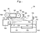
- Fig. 6 is a side view showing a section of a paper feeder 38 in a copying machine 22
- Fig. 7 is a plan view of Fig. 6
- Fig. 8 is an exploded perspective view of the paper feeder 38
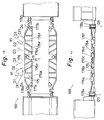
- Fig. 9 is a simplified plan view of the paper feeder 38.
- the other paper feeders 39, 40 are composed alike.
- the constituent elements of the paper feeder in this embodiment are similar to the constituent elements in the paper feeder 21 in the foregoing embodiments, except that this embodiments relates to the top-taking structure while the paper feeder 21 is of so-called bottom-taking top-returning structure.
- the paper feeder 38 comprises a frame body 148 in which recording papers are stacked and stored, and a feeding unit 220 for separating and feeding one by one the recording papers stacked and stored in the frame body 148, and the frame body 148 incorporates a laying plate 149 being driven vertically by a lifting mechanism mentioned below on which recording papers P are stacked up.
- the laying plate 149 has a slot 150 extending in the feeding direction A2, and a guide rail 151 extending along the feeding direction A2 is formed beneath the laying plate 149.
- This guide rail 151 is provided with a mounting part 153 of a rear end defining member 152, slidably in the longitudinal direction, through plural insertion holes 154 in the mounting part 153.
- the rear end defining member 152 is provided with a defining part 155 extending above the laying plate 149 through the slots 150 of the laying plate 149 disposed in the mounting part 153.
- an upper limit sensor 156 such as limit switch is provided, and when an excessive recording paper P is put on the laying plate 149, it is detected.
- an upper limit switch 185 realized, for example, by a limit switch is provided, and it is detected that the top recording paper P1 of the recording papers P stacked up on the laying plate 149 has a predetermined gap of H4 to the feeding stretch belt 157. That is, when the top recording paper P1 approaches abnormally, exceeding the distance of H4 to the feeding stretch belt 157, the upper limit sensor 185 is actuated to stop elevation of the recording paper.
- the paper feeder 38 is provided with, for example, four feeding stretch belts 157a to 157d at predetermined positions with respect to the frame body 148. These feeding stretch belts 157a to 157d are stretched respectively on the rollers 160a to 160d; 161a to 161d fixed on the rotary shafts 158, 159. Between the rollers 160 and 161, a vacuum attracting box 162 is stored, which comprises a main body 164 forming attracting ports 163a to 163d opposite to the feeding stretch belts 157a to 157d, and a cover body 165 covering the main body 164.
- a damper 166 is contained in the vacuum attracting box 162, and a vacuum source (not shown) to which the vacuum attracting box 162 and the vacuum attracting box 162 are communicated/shut off.
- the attracting box 162 is supported by a support member 260 fixed on the frame body 148.
- protrusions 167a, 167b extending along the feeding direction A2 and projecting downward are formed, and they project downward from between the feeding stretch belts 157a, 157b, and feeding stretch belts 157c, 157d.
- a nozzle member 168 is provided at the downstream side of the feeding direction A2 of the frame body 148 and beneath the feeding stretch belt 157.
- the nozzle member 168 contains the main body 169 and cover body 170, and a damper 171 is included in an internal air passage 216, thereby communicating/shutting off the blower (not shown) and the nozzle member 168.
- the laying plate 149 in the frame body 148 is provided with slots 209, 210 along the widthwise direction, and lateral end defining plates 195, 196 are inserted from top to bottom of the laying plate 149.
- one longitudinal end of the driving members 197, 198 extending along the widthwise direction is fixed.
- racks 199, 200 are formed, and these racks 199, 200 are engaged mutually from the opposite sides with a pinion 201 rotatably disposed on a support plate 149 disposed between the driving members 197, 198.
- a widthwise displacement position is detected, for example, by three positions sensors S1, S2, S3 which are disposed from outward to Inward in the widthwise direction.
- the lateral end defining plates 195, 196 cooperate with each other by means of the racks 199, 200 and pinion 201, and by aligning the distance of the lateral end defining plates 195 in the widthwise length of the stored recording papers P, the widthwise length of the stored recording papers can be detected on the basis of the output from the position sensors S1 to S3.
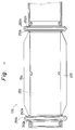
- Fig. 10 is a front view of the main body 169
- Fig. 11 is a plan view of the main body 169
- Fig. 12 is a back view of the main body 169
- Figs. 13 to 17 are sectional views seen from the sectional lines A-A, B-B, C-C, D-D in Fig. 34.
- the main body 169 comprises a flat plate 172 extending in the widthwise direction, and slopes 173, 174 consecutive to the vertical direction thereof and Inclined by an angle ⁇ 3 (e.g. 20 degrees) to the main body 148 side.
- nozzle holes 176a to 176f forming the same jet flows D1 to D3 as the jet flows C1 to C3 by the nozzle 96 in the foregoing embodiment are formed by the adjacent guide pieces 175, and the nozzle is composed of the nozzle holes 176a to 176f and the adjacent guide pieces 175.
- the nozzle holes 176a, 176f form a jet flow of arrow D1 toward the feeding stretch belt 157, in the vertical plane parallel to the feeding direction A2.
- the nozzle holes 176b, 176f have an angle of ⁇ 11 (e.g. 30 degrees) to the feeding direction A2 in a plan view, and form a jet flow expressed by arrow D2 directed to the feeding stretch belt 157.
- the nozzle holes 176c, 176d form a jet flow and an air flow parallel to the arrow D2 and indicated by arrow D3.
- the jet flows D1, D2 are converged and synthesized on the central line 11 to form an air flow D11.
- the flow is injected to the position remote to the downstream side by the predetermined distance L5 from the downstream side end part of the feeding direction of the recording paper attracted so as to cover the attracting region 108 defined by the attracting vacuum box 162 and the range exceeding to the downstream side of the feeding direction A2.
- the reflected air flow from the feeding stretch belt 157 is blown and injected between the top recording paper P1 and the second recording paper P2.
- the injected air flow is inflated in the vertical direction, thereby separating the recording papers P1, P2.
- nozzle holes 177a, 177b having the sectional shapes as shown in Figs. 14 and 15.
- the nozzle holes 177a, 177b are composed at an inclination outward in the widthwise direction as going upstream in the feeding direction at an angle of ⁇ 12 (e.g. 40 degrees) with respect to the widthwise direction as shown in Fig. 12 outward in the widthwise direction, and are composed at an inclination to the upstream side of the feeding direction A2 as going from downward topward by an angle of ⁇ 13 (e.g. 65.7 degrees) from the vertical direction as shown in Fig. 14.
- the jet flow and air flow are injected as indicated by arrow D4.
- grooves 178a, 178b parallel to the feeding direction A2 are formed as the sectional shape is shown in Fig. 16.
- the grooves 178a, 178b are covered with the cover body 170 as shown in Fig. 16, and form a jet flow and an air flow parallel to the feeding direction A2 (indicated by arrow D5).
- the cover body 170 shown in Fig. 13 is put on thus composed main body 169.
- fitting projections 251a and 251b having a pair of upper and lower nozzle holes 252a and 252b are formed.
- These projections 251a and 251b are projected in the feeding direction A2, and the nozzle holes 252a and 252b are composed by the holes 250a, 178a; 250b and 178b in the state of being fitted to the grooves 178a and 178b of the main body 169. From these nozzle holes 252a and 252b, a jet flow may be formed in the direction of arrow D5 as shown in Fig. 16.
- a pair of upper and lower ribs 254 and 255 are integrally formed on the end plate 253 of such cover body 170, and by these ribs 254 and 255, the nozzle holes 176a to 176e are defined in the state of communicating in the direction of jet flows D1 to D3.
- Fig. 18 is a perspective view showing the composition of elevating the laying plate 149 in the paper feeder 38.
- plural pulleys 180a to 180f are disposed as shown in the drawing at a predetermined height H5 from the bottom of the frame body 148, and pulleys 180g to 180j are disposed at a position of a predetermined height H6 from the bottom.
- a wire 181 is applied on these pulleys 180a to 180j, and the both ends of the wire 181 are wound around a driving roller 183 rotated by a pulse motor 182.
- support pieces 184a to 184d from mounting the four corners of the laying plate 149 are fixed.
- the driving roller 183 is rotated in the direction of arrow E1 by the pulse motor 182, the laying plate 149 is elevated, while the laying plate 149 is lowered.
- the highest recording paper P1 in the vertical direction of the recording papers P put on the laying plate 149 is maintained at a position remote by a predetermined distance of H4 from the feeding stretch belts 157a to 157d. Consequently, a favorable vacuum attracting action of the top recording paper P by the feeding stretch belts 157a to 157d may be realized.
- Fig. 19 is a perspective view for explaining the basic function of each air flow indicated by arrows D1 to D5 and D11 from the nozzle holes 176a to 176f; 177a, 177b; 178a and 178b.
- the jet flows of arrows D1 and D2 are concentrated as an air flow D11 in the widthwise direction of the recording paper P, and it is blown in and injected in the gap formed as shown below between the top recording paper P1 and the second recording paper P2, and is inflated in the vertical direction to separate the recording papers P1 and P2.
- the air flow indicated by arrow D3 also separates the recording papers P1 and P2 as mentioned below.
- the air flow D5 from the nozzle holes 178a and 178b is an air stream injected parallel to the feeding direction A2 in the relatively upward portion of the stacked recording papers P, and it maintains a plurality of recording papers P near the upper part always in a lifted state.
- the air flow indicated by arrow D4 from the nozzle holes 177a and 177b pushes up the uppermost recording paper P1 of the plurality of recording papers P lifted by the air flow of arrow D5 to the feeding stretch belt 157 side, and the recording paper P1 is attracted in vacuum to the feeding stretch belt 157 by the negative pressure by the vacuum attracting box 162.
- the recording papers P are separated by the air flows indicated by arrows D11 and D3.
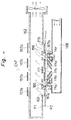
- Fig. 20 is a sectional view explaining the separating action of the recording papers P in the paper feeder 38.
- the structure is shown in a simplified form in Fig. 20.
- the nozzle holes 176a to 176f and the guide pieces 175 for defining them are collectively called a handling nozzle and indicated by same reference number.
- the nozzle holes 177a, 177b; 179a and 179b and guide pieces 175 for defining them are called pushing nozzle and lifting nozzle, respectively, and indicated by same reference numbers.
- the floating recording papers P are attracted vacuum to the lower stretching part 215 of the feeding stretch belt 157.
- the top recording paper P1 at this time is attracted In vacuum to the lower stretching part 215 of the feeding stretch belt 157 while being lifted by the protrusions 167a, 167b projecting downward from within the feeding stretch belt 157, being formed in the vacuum attracting box 162.
- the second recording paper P2 is prevented from being attracted to the feeding stretch belt 157 because almost entire portion of the lower stretched part 215 of the feeding stretch belt 157 is covered by the recording paper P1. If attracted, it is only relatively weakly attracted. Accordingly, as shown in Fig. 20, a gap 186 is produced between the recording papers P1 and P2, near the protrusions 167a and 167b.
- the air flow in the direction of arrow D3 from the handling nozzles 176c and 176d is attracted into the gap 186, and realizes the same separating action.
- the pushing nozzles 177a and 177b are to lift one or plural recording papers P of the uppermost area of the floating recording papers P to the feeding stretch belt 157 side.
- air flows C11 and C3 inflating in the vertical direction are formed at symmetrical positions about the widthwise central position CNT of the recording paper, and a satisfactory separating action is realized whether the recording papers P being used are relatively large or small in size.
- the air flow from the nozzle member 168 is concentrated in the widthwise plural positions to the recording papers P, and if the recording papers are relatively small in size or weight, scattering of the recording papers P by the air flow from the handling nozzles 176a to 176f without being attracted to the feeding stretch belt 157 may be avoided.
- Fig. 21 is a sectional view showing other constitutional example of the feeding unit 220 of the paper feeder 38.
- This embodiment is similar to the foregoing embodiments, and corresponding parts are identified with same reference numbers.
- the protrusion 167 formed in the vacuum attracting box 162 is determined so as to be positioned in the widthwise central position CNT between the feeding stretch belts 157b and 157c, and that attracting ports 163e and 163f are disposed in the vacuum attracting box 162 between the feeding stretch belts 157a and 157b, and between the feeding stretch belts 157c and 157d.
- the recording paper P on the laying plate 149 is lifted by the lifting nozzles 179a and 179b, and the lifted recording paper P is pushed up by the pushing nozzles 177a and 177b to the feeding stretch belt 157 side.
- the vacuum attracting box 162 When the vacuum attracting box 162 generates a negative pressure, the top recording paper P1 is attracted to the feeding stretch belt 157, but the range opposing the attracting ports 163e and 163f is the gap of the feeding stretch belt 157, and therefore the recording paper p1 is attracted and dented to the vacuum attracting box 162 side as shown in Fig. 17. It is the same with the recording paper P1 opposing the attracting port 163f. Furthermore, the recording paper P1 is lifted in the direction of going away from the vacuum attracting box 162 by the protrusion 167 formed in the central position CNT.
- a gap 186 is formed at the position corresponding to the attracting ports 163e, 163f and protrusion 167. Therefore, the air flows C11, C3 due to handling nozzles 176a to 176f are injected into the gap 186, and inflated in the vertical direction as mentioned above to separate the recording papers P1 and P2. In such embodiment, too, the same effect as mentioned in the foregoing embodiments is achieved.
- the protrusions 167a, 167b are not limited to the shape continuous on a straight line, but may be formed in a shape of single projection of circular head, for example, and a plurality of such protrusions may be composed along the feeding direction A2.
- it is composed so that the recording paper may be attracted to the feeding stretch belts 46a to 46c, 157a to 157d and 208, in a range exceeding the attracting region 108, and that the air flow for separation is once injected to a remote position preliminarily to the downstream side in the feeding direction from the downstream side end part of the feeding direction A2 of the recording paper as mentioned above, thereby the reflected flow acts to separate the recording papers.
- the recording paper when the recording paper is relatively small in size, it may be also designed that the recording paper may be exposed, not covered, near the downstream side end portion of the attracting region 108. In such a case, the air flow for separating is attracted into the attracting region 108, and the flow rate is suppressed. Therefore, scatter of the small-sized recording paper by the air flow of large flow rate may be avoided. In the case of recording papers of relatively large size or large weight, it is enough to suck as in the preceding embodiment.
- the ends of one side in the widthwise direction of sheets may be stacked up on the laying plate, and the papers may be fed in this end aligned state.
- the rear end defining members 58 and 152 may be designed to detect the size of the sheets (that is, width or length) or the pile of the stack by detecting means, thereby driving to displace forward or backward in the feeding direction.
- the invention may be applied in a wide range, not only for feeding the recording papers of copying machine, but for feeding the recording papers of a printer, or feeding other sheets than recording papers.
Landscapes
- Engineering & Computer Science (AREA)
- Mechanical Engineering (AREA)
- Sheets, Magazines, And Separation Thereof (AREA)
- Paper Feeding For Electrophotography (AREA)
- Exposure Or Original Feeding In Electrophotography (AREA)
- Conveyance By Endless Belt Conveyors (AREA)
Claims (9)
- Vorrichtung zum Zuführen eines Deckblatts, die aufweist:- eine Auflageplatte (149), auf der viele Blätter (P) übereinander gestapelt sind,- Zufuhrglieder (220), die oberhalb der Blätter (P) auf der Auflageplatte (149) an mehreren Stellen in ihrer Breitenrichtung angeordnet sind, um das Deckblatt (P1) durch Einwirken von Unterdruck auf die Zufuhrfläche anzuziehen und dieses Deckblatt durch eine teilweise Verformung nach oben beim Einwirken des Unterdrucks zumindest auf seinen in Zufuhrrichtung (A2) stromabwärts gelegenen Endabschnitt an in Breitenrichtung liegenden Stellen zu fördern, wobei die Zufuhrglieder aufweisen:- mehrere Förderlaufbänder (157), die eine Vielzahl Luftdurchtrittslöcher (103) aufweisen, die unter gegenseitigen Abständen (103) in der Breitenrichtung angebracht sind,- Antriebsglieder (160, 161) für den Drehantrieb der Förderlaufbänder (157) und- einen nach unten offenen Unterdrucksaugkasten (162), der unmittelbar über dem nahezu horizontalen unteren Teil (215) der Laufbänder (157) angeordnet ist, und- Luftstrombildungsmittel (168), die in Zufuhrrichtung an der stromabwärtigen Seite der Auflageplatte (149) angeordnet sind, um einen Luftstrom (D, D1-D5) auf die verformten Teile des Deckblatts (P1) zu richten und zu blasen, während das Deckblatt durch den auf die Zufuhrfläche einwirkenden Unterdruck angesaugt wird,
dadurch gekennzeichnet, daß- Vorsprünge (167) an festen Stellen zwischen Saugabschnitten (163) des offenen unteren Teils (164) des Unterdrucksaugkastens (162) liegen, die an mehreren Intervallen der jeweiligen unteren Abschnitte der sich in Zufuhrrichtung erstreckenden Förderlaufbänder liegen und von der Zufuhrfläche der unteren Bandteile der Förderlaufbänder nach unten vorstehen, und- daß die Luftstrombildungsmittel (168) so angeordnet sind, daß sie Luftströme (D) in die Nachbarschaft der Vorsprünge (167) blasen. - Deckblattzufuhrvorrichtung nach Anspruch 1, bei der der Luftstrom (D) zu den verformten Teilen des Deckblatts (P1) aus in Breitenrichtung nach außen gerichteten Luftströmen (D2, D3) und parallel zur Zufuhrrichtung (A2) gerichteten Luftströmen (D1) besteht.
- Deckblattzufuhrvorrichtung nach Anspruch 1, bei der die Luftströme (D2, D3) zu den einzelnen Vorsprüngen (167) in Breitenrichtung nach außen gerichtet sind.
- Deckblattzufuhrvorrichtung nach Anspruch 1, bei der die Luftströme (D1) zu einzelnen Vorsprüngen (167) parallel zur Zufuhrrichtung (A2) gerichtet sind.
- Deckblattzufuhrvorrichtung nach Anspruch 1, bei der die Luftströme (D1) zu den einzelnen Vorsprüngen (167) eine Kombination aus in Breitenrichtung nach außen gerichteten Luftströmen und in Zufuhrrichtung (A2) parallel gerichteten Luftströmen sind.
- Deckblattzufuhrvorrichtung nach Anspruch 1, bei der sich die Vorsprünge (167) in einer schlanken Form längs der Zufuhrrichtung erstrecken.
- Deckblattzufuhrvorrichtung nach Anspruch 1, bei der die Auflageplatte (149) symmetrisch auf der rechten und linken Seite der an der zentralen Stelle in Breitenrichtung liegenden symmetrischen Oberfläche gebildet ist, und die Luftstrombildungsmittel (168) Luftströme von symmetrischen Positionen auf der rechten und linken Seite der symmetrischen Oberfläche aus blasen.
- Deckblattzufuhrvorrichtung nach Anspruch 1, bei der die Luftstrombildungsmittel (168) aufweisen:- ein Düsenglied (168), das eine erste Düsenöffnung (176B), (176C), (176D), (176e) und eine zweite Düsenöffnung (179) zur Bildung der Luftströme (D) aufweist, wobei- die erste Düsenöffnung (176B), (176C), (176D), (176e) Luftströme (D2, D3) in Breitenrichtung nach außen bläst, die dann stromaufwärts in Zufuhrrichtung (A2) in Richtung auf den verformten Blatteil von der zentralen Seite in Breitenrichtung gehen, und- eine zweite Düse (176a), (176b) Luftströme zur stromaufwärtigen Seite nahezu parallel zur Zufuhrrichtung (A2) in Richtung auf den verformten Blatteil bläst.
- Deckblattzufuhrvorrichtung nach Anspruch 8, bei der die Vorsprünge (167) so angeordnet sind, daß sie nach einer Seite in Breitenrichtung innerhalb gegenseitiger Intervalle der unteren Teile (215) der Laufbänder (157) verschoben sind und ein unterdruckdeformierender Raum gegen die seitliche Kante eines der unteren Teile der Laufbänder (215) hin gebildet wird, und- der Luftstrom von der Seite des unterdruckdeformierenden Raums in Richtung auf den Vorsprung (167) geblasen wird.
Applications Claiming Priority (2)
| Application Number | Priority Date | Filing Date | Title |
|---|---|---|---|
| JP70918/90 | 1990-03-20 | ||
| JP2070918A JP2578238B2 (ja) | 1990-03-20 | 1990-03-20 | 最上部シートの給送装置 |
Publications (3)
| Publication Number | Publication Date |
|---|---|
| EP0448081A2 EP0448081A2 (de) | 1991-09-25 |
| EP0448081A3 EP0448081A3 (en) | 1993-02-03 |
| EP0448081B1 true EP0448081B1 (de) | 1996-09-11 |
Family
ID=13445365
Family Applications (1)
| Application Number | Title | Priority Date | Filing Date |
|---|---|---|---|
| EP91104344A Expired - Lifetime EP0448081B1 (de) | 1990-03-20 | 1991-03-20 | Vorrichtung zum Zuführen eines Deckblatts |
Country Status (4)
| Country | Link |
|---|---|
| US (1) | US5181710A (de) |
| EP (1) | EP0448081B1 (de) |
| JP (1) | JP2578238B2 (de) |
| DE (1) | DE69121943T2 (de) |
Families Citing this family (12)
| Publication number | Priority date | Publication date | Assignee | Title |
|---|---|---|---|---|
| JPH0825649B2 (ja) * | 1990-05-09 | 1996-03-13 | シャープ株式会社 | シート給送装置 |
| JP2609477B2 (ja) * | 1990-05-09 | 1997-05-14 | シャープ株式会社 | 複数サイズシートの給送装置 |
| US5228675A (en) * | 1992-01-28 | 1993-07-20 | Baumfolder Corporation | Sheet separation pile feeder |
| US5344133A (en) * | 1993-02-25 | 1994-09-06 | Eastman Kodak Company | Vacuum belt feeder having a positive air pressure separator and method of using a vacuum belt feeder |
| US5645274A (en) * | 1993-09-22 | 1997-07-08 | Canon Kabushiki Kaisha | Sheet supply apparatus |
| JP3097889B2 (ja) * | 1993-10-01 | 2000-10-10 | キヤノン株式会社 | シート給送装置及び画像形成装置 |
| US6412769B1 (en) | 1999-06-28 | 2002-07-02 | Kyocera Mita Corporation | Paper feeder |
| US6398207B1 (en) * | 2000-06-12 | 2002-06-04 | Xerox Corporation | Sheet feeding apparatus having an air plenum with a seal |
| US6398208B1 (en) * | 2000-06-12 | 2002-06-04 | Xerox Corporation | Sheet feeding apparatus having an air plenum with a leaky seal |
| US6398206B1 (en) * | 2000-06-12 | 2002-06-04 | Xerox Corporation | Sheet feeding apparatus having an air plenum with a corrugated surface |
| US8419008B2 (en) | 2009-01-30 | 2013-04-16 | Canon Kabushiki Kaisha | Image forming apparatus |
| JP2011190000A (ja) * | 2010-03-12 | 2011-09-29 | Seiko Epson Corp | 記録装置 |
Family Cites Families (21)
| Publication number | Priority date | Publication date | Assignee | Title |
|---|---|---|---|---|
| US3033562A (en) * | 1960-02-05 | 1962-05-08 | Jr Charles H Kretz | Vacuum-blast pickups for sheet material |
| US3198514A (en) * | 1963-05-10 | 1965-08-03 | Gen Electric | Document feeding system |
| JPS5519859A (en) * | 1978-07-28 | 1980-02-12 | Nec Corp | Ring laser |
| US4324395A (en) * | 1979-10-03 | 1982-04-13 | Xerox Corporation | Sheet separator |
| US4418905A (en) * | 1981-11-02 | 1983-12-06 | Xerox Corporation | Sheet feeding apparatus |
| US4451028A (en) * | 1981-11-27 | 1984-05-29 | Xerox Corporation | Sheet feeding apparatus |
| JPS6127845A (ja) * | 1984-07-16 | 1986-02-07 | Fuji Xerox Co Ltd | 紙送り装置 |
| US4596385A (en) * | 1984-09-27 | 1986-06-24 | Xerox Corporation | Top vacuum corrugation feeder with moveable air blocking vane |
| JPH066453B2 (ja) * | 1985-04-17 | 1994-01-26 | 富士ゼロックス株式会社 | エア−式給紙装置用給紙トレイ |
| JPS61254438A (ja) * | 1985-05-01 | 1986-11-12 | Fuji Xerox Co Ltd | 給紙装置 |
| JPS6216944A (ja) * | 1985-07-16 | 1987-01-26 | Fuji Xerox Co Ltd | 給紙装置 |
| JPS6216947A (ja) * | 1985-07-16 | 1987-01-26 | Fuji Xerox Co Ltd | 給紙装置 |
| US4627605A (en) * | 1985-11-06 | 1986-12-09 | Xerox Corporation | Front air knife top vacuum corrugation feeder |
| US4635921A (en) * | 1985-11-06 | 1987-01-13 | Xerox Corporation | Front air knife top vacuum corrugation feeder |
| US4699369A (en) * | 1986-06-27 | 1987-10-13 | Xerox Corporation | Front air knife improvement for a top vacuum corrugation feeder |
| JPS6417139A (en) * | 1987-07-13 | 1989-01-20 | Mitsubishi Electric Corp | Memory device |
| JPH0288538A (ja) * | 1988-09-27 | 1990-03-28 | Ube Ind Ltd | 2―ヒドロキシ―2―(4―置換フエニル)プロピオン酸類の製造方法 |
| US4887805A (en) * | 1988-03-10 | 1989-12-19 | Xerox Corporation | Top vacuum corrugation feeder |
| JPH0270632A (ja) * | 1988-09-02 | 1990-03-09 | Hitachi Ltd | 紙葉類分離装置 |
| JP2934442B2 (ja) * | 1988-09-19 | 1999-08-16 | 株式会社日立製作所 | 紙葉類分離給送装置及び紙葉類分離給送方法 |
| US5190276A (en) * | 1990-03-13 | 1993-03-02 | Sharp Kabushiki Kaisha | Sheet feeding apparatus |
-
1990
- 1990-03-20 JP JP2070918A patent/JP2578238B2/ja not_active Expired - Lifetime
-
1991
- 1991-03-20 DE DE69121943T patent/DE69121943T2/de not_active Expired - Fee Related
- 1991-03-20 EP EP91104344A patent/EP0448081B1/de not_active Expired - Lifetime
- 1991-03-20 US US07/672,654 patent/US5181710A/en not_active Expired - Lifetime
Also Published As
| Publication number | Publication date |
|---|---|
| EP0448081A2 (de) | 1991-09-25 |
| JPH03272942A (ja) | 1991-12-04 |
| US5181710A (en) | 1993-01-26 |
| DE69121943T2 (de) | 1997-04-03 |
| JP2578238B2 (ja) | 1997-02-05 |
| EP0448081A3 (en) | 1993-02-03 |
| DE69121943D1 (de) | 1996-10-17 |
Similar Documents
| Publication | Publication Date | Title |
|---|---|---|
| CA1317325C (en) | Top vacuum corrugation feeder | |
| US6543759B2 (en) | Paper feeder for use in image forming apparatus | |
| JP2578812B2 (ja) | 上側シ−ト給送装置 | |
| JPS5895046A (ja) | シ−ト給送装置 | |
| JPH0423747A (ja) | 給紙装置 | |
| US5190276A (en) | Sheet feeding apparatus | |
| US5181710A (en) | Top sheet feeding apparatus | |
| US5967507A (en) | Automatic document handler having non-relative motion vacuum corrugating device | |
| EP0448090B1 (de) | Apparat zum Zuführen von Blättern | |
| EP0457191B1 (de) | Blattzuführvorrichtung für mehrere Blattformate | |
| US7290764B2 (en) | Modular guide apparatus for tab stock received in a feeder tray | |
| JPS61140433A (ja) | 底部シート分離・給送装置 | |
| EP0456233B1 (de) | Apparat zum Zuführen von Blättern | |
| US4381893A (en) | Recirculating document lateral registration | |
| CA1279878C (en) | Plural level vacuum document feeder | |
| JP2927992B2 (ja) | スタックシート底部分離および供給装置 | |
| JPS5978019A (ja) | 下側シ−ト分離給送装置 | |
| JPH03211136A (ja) | 給紙装置 | |
| US5181711A (en) | Device for discharging sheets from the bottom of a stack | |
| JPH0489729A (ja) | 最上部シートの給送装置 | |
| EP0676348A1 (de) | Blattzuführvorrichtung | |
| JP2502398B2 (ja) | 複数サイズシ―トの給送装置 | |
| JPH034463B2 (de) | ||
| JPH05286596A (ja) | 最上部シートの給送装置 | |
| JP2001039556A (ja) | 給紙装置 |
Legal Events
| Date | Code | Title | Description |
|---|---|---|---|
| PUAI | Public reference made under article 153(3) epc to a published international application that has entered the european phase |
Free format text: ORIGINAL CODE: 0009012 |
|
| 17P | Request for examination filed |
Effective date: 19910320 |
|
| AK | Designated contracting states |
Kind code of ref document: A2 Designated state(s): DE FR GB |
|
| PUAL | Search report despatched |
Free format text: ORIGINAL CODE: 0009013 |
|
| AK | Designated contracting states |
Kind code of ref document: A3 Designated state(s): DE FR GB |
|
| 17Q | First examination report despatched |
Effective date: 19950120 |
|
| GRAH | Despatch of communication of intention to grant a patent |
Free format text: ORIGINAL CODE: EPIDOS IGRA |
|
| GRAH | Despatch of communication of intention to grant a patent |
Free format text: ORIGINAL CODE: EPIDOS IGRA |
|
| GRAA | (expected) grant |
Free format text: ORIGINAL CODE: 0009210 |
|
| AK | Designated contracting states |
Kind code of ref document: B1 Designated state(s): DE FR GB |
|
| REF | Corresponds to: |
Ref document number: 69121943 Country of ref document: DE Date of ref document: 19961017 |
|
| ET | Fr: translation filed | ||
| PLBE | No opposition filed within time limit |
Free format text: ORIGINAL CODE: 0009261 |
|
| STAA | Information on the status of an ep patent application or granted ep patent |
Free format text: STATUS: NO OPPOSITION FILED WITHIN TIME LIMIT |
|
| 26N | No opposition filed | ||
| REG | Reference to a national code |
Ref country code: GB Ref legal event code: IF02 |
|
| PGFP | Annual fee paid to national office [announced via postgrant information from national office to epo] |
Ref country code: GB Payment date: 20090318 Year of fee payment: 19 |
|
| PGFP | Annual fee paid to national office [announced via postgrant information from national office to epo] |
Ref country code: DE Payment date: 20090313 Year of fee payment: 19 |
|
| PGFP | Annual fee paid to national office [announced via postgrant information from national office to epo] |
Ref country code: FR Payment date: 20090316 Year of fee payment: 19 |
|
| GBPC | Gb: european patent ceased through non-payment of renewal fee |
Effective date: 20100320 |
|
| REG | Reference to a national code |
Ref country code: FR Ref legal event code: ST Effective date: 20101130 |
|
| PG25 | Lapsed in a contracting state [announced via postgrant information from national office to epo] |
Ref country code: FR Free format text: LAPSE BECAUSE OF NON-PAYMENT OF DUE FEES Effective date: 20100331 |
|
| PG25 | Lapsed in a contracting state [announced via postgrant information from national office to epo] |
Ref country code: DE Free format text: LAPSE BECAUSE OF NON-PAYMENT OF DUE FEES Effective date: 20101001 |
|
| PG25 | Lapsed in a contracting state [announced via postgrant information from national office to epo] |
Ref country code: GB Free format text: LAPSE BECAUSE OF NON-PAYMENT OF DUE FEES Effective date: 20100320 |