EP0448145A2 - Méthode pour commander la vitesse d'un moteur - Google Patents
Méthode pour commander la vitesse d'un moteur Download PDFInfo
- Publication number
- EP0448145A2 EP0448145A2 EP91200471A EP91200471A EP0448145A2 EP 0448145 A2 EP0448145 A2 EP 0448145A2 EP 91200471 A EP91200471 A EP 91200471A EP 91200471 A EP91200471 A EP 91200471A EP 0448145 A2 EP0448145 A2 EP 0448145A2
- Authority
- EP
- European Patent Office
- Prior art keywords
- motor
- current
- speed
- piston
- pressure
- Prior art date
- Legal status (The legal status is an assumption and is not a legal conclusion. Google has not performed a legal analysis and makes no representation as to the accuracy of the status listed.)
- Withdrawn
Links
Images
Classifications
-
- B—PERFORMING OPERATIONS; TRANSPORTING
- B60—VEHICLES IN GENERAL
- B60T—VEHICLE BRAKE CONTROL SYSTEMS OR PARTS THEREOF; BRAKE CONTROL SYSTEMS OR PARTS THEREOF, IN GENERAL; ARRANGEMENT OF BRAKING ELEMENTS ON VEHICLES IN GENERAL; PORTABLE DEVICES FOR PREVENTING UNWANTED MOVEMENT OF VEHICLES; VEHICLE MODIFICATIONS TO FACILITATE COOLING OF BRAKES
- B60T8/00—Arrangements for adjusting wheel-braking force to meet varying vehicular or ground-surface conditions, e.g. limiting or varying distribution of braking force
- B60T8/32—Arrangements for adjusting wheel-braking force to meet varying vehicular or ground-surface conditions, e.g. limiting or varying distribution of braking force responsive to a speed condition, e.g. acceleration or deceleration
- B60T8/34—Arrangements for adjusting wheel-braking force to meet varying vehicular or ground-surface conditions, e.g. limiting or varying distribution of braking force responsive to a speed condition, e.g. acceleration or deceleration having a fluid pressure regulator responsive to a speed condition
- B60T8/42—Arrangements for adjusting wheel-braking force to meet varying vehicular or ground-surface conditions, e.g. limiting or varying distribution of braking force responsive to a speed condition, e.g. acceleration or deceleration having a fluid pressure regulator responsive to a speed condition having expanding chambers for controlling pressure, i.e. closed systems
- B60T8/4208—Debooster systems
- B60T8/4266—Debooster systems having an electro-mechanically actuated expansion unit, e.g. solenoid, electric motor, piezo stack
-
- Y—GENERAL TAGGING OF NEW TECHNOLOGICAL DEVELOPMENTS; GENERAL TAGGING OF CROSS-SECTIONAL TECHNOLOGIES SPANNING OVER SEVERAL SECTIONS OF THE IPC; TECHNICAL SUBJECTS COVERED BY FORMER USPC CROSS-REFERENCE ART COLLECTIONS [XRACs] AND DIGESTS
- Y10—TECHNICAL SUBJECTS COVERED BY FORMER USPC
- Y10S—TECHNICAL SUBJECTS COVERED BY FORMER USPC CROSS-REFERENCE ART COLLECTIONS [XRACs] AND DIGESTS
- Y10S303/00—Fluid-pressure and analogous brake systems
- Y10S303/02—Brake control by pressure comparison
- Y10S303/03—Electrical pressure sensor
- Y10S303/04—Pressure signal used in electrical speed controlled braking circuit
Definitions
- This invention relates to a method of controlling the speed of a motor for use, for example, in a motor driven pressure modulator where the torque of the motor is controlled to limit the speed of the motor.
- motor driven pressure modulators are known.
- such uses include a motor driven braking pressure modulator in vehicle anti-lock braking systems.
- a DC torque motor drives a piston in a cylinder whose volume is modulated to control the hydraulic pressure at the wheel brake.
- the motor is controlled to position the piston in an initial, fully extended home position at which a check valve is unseated to couple the brake system master cylinder to the wheel brake to allow normal braking.
- the motor retracts the piston (which allows the check valve to close to isolate the master cylinder from the wheel brake as long as the wheel brake pressure is greater than the master cylinder pressure) to reduce brake pressure and thereafter modulates the piston position to provide pressure control for anti-lock braking.
- the motor returns the piston to its extended home position. While controlling the pressure, there is a direct relationship between the motor current, motor torque and the hydraulic pressure acting on the head of the piston.
- a motor driven pressure modulator such as described above. For example, it is desirable to limit the speed at which the motor repositions the piston to the extended home position such as upon termination of anti-lock controlled braking so as to prevent damage to the modulator when the piston head reaches its end of travel.
- an unknown speed dependent factor when repositioning the piston is the brake pressure on the head of the piston.
- the pressure at the piston head is established by the vehicle operator via the normal brake system and may vary from no pressure to a relatively high braking pressure. Therefore, the speed of the motor for a given motor current command may vary widely. For example, when the motor load (i.e., the operator applied hydraulic brake pressure on the piston head) is equal to the motor torque, the motor does not rotate and the piston remains stationary. Conversely, when the load on the motor is small compared to the motor torque, the motor rotates at a high rate and the piston travels at a high speed. Therefore, care must be taken in the control of a motor driven pressure modulator to avoid situations in which the actual wheel brake pressure is substantially lower than the motor torque being commanded. When such a condition exists, motor torque must be controlled so as to prevent damage to the actuator when it reaches its end of travel.
- the present invention seeks to provide a method and system for controlling the speed of a motor for use, for example, in a motor driven pressure modulator.
- an aspect of the present invention provides a method of controlling the speed of a motor as defined in claim 1.
- the invention can provide for the control of the speed of a motor driven pressure modulator that adapts to varying modulator load conditions.
- the motor current is preferably controlled as a function of the load on the motor as represented by the acceleration of the motor in response to motor stall current being commanded to the motor.
- the stall current command results in system voltage being applied to the motor.
- acceleration of the motor may be represented by the time for the motor current to decrease to a predetermined level below the motor stall current when system voltage is applied to the motor.
- the system voltage is advantageously applied to the motor for a load dependent time period varying in direct proportion to load, and then removed for a load dependent wait period varying in inverse proportion to load.
- the load dependent time period for applying system voltage is represented by the time for the motor current to decrease from the motor stall current to a predetermined level below the stall current.
- the wait period and the voltage application period preferably comprise a control cycle that is repeated.
- the time of the control cycle is a constant.
- maximum current is commanded to the motor by application of system voltage resulting in the motor current initially rising rapidly to the motor stall current, which is a function of the motor resistance and applied voltage.
- the motor torque which is a function of the motor current torque relationship
- the motor accelerates at a rate that is a function of the difference between the motor torque and the load torque represented by the load on the modulator.
- the load is represented by the pressure on the piston head.
- EMF back electro-magnetic force
- the acceleration of the motor and therefore the rate of decrease of motor current is a function of the difference between the motor torque and the load torque.
- the motor current decreases below the stall current by a predetermined amount representing a predetermined speed of the motor
- the motor current is turned off for a period of time referred to as a wait period that is based upon the time taken for the motor speed to attain the predetermined speed.
- the sum of the time during which the motor current is applied and the wait period is equal to a constant interval. After the end of the interval, maximum motor current is again commanded and the cycle repeated to provide for motor speed control.
- the time for the motor to achieve the predetermined speed is greater resulting in a short wait time. If the motor loading is such that the motor speed never attains the predetermined speed, motor current is applied to the motor continuously for the whole interval. The result of this is the control of a motor which is adaptable to the motor load to control the motor speed.
- the present invention is also directed to apparatus for carrying out the steps of the claimed method.
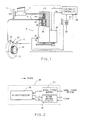
- a wheel lock control system for a wheel of a motor vehicle is illustrated in Figure 1.
- the wheel (not shown) includes a brake unit 10 operated by hydraulic pressure provided by a master cylinder 12 and a hydraulic boost unit 14 operated by the vehicle driver.
- the hydraulic fluid under pressure from the master cylinder 12 is fed to the brake unit 10 via brake lines 16 and a pressure modulator 18.
- the brake unit 10 illustrated is a disc brake system which includes a caliper 20 located on a rotor 22.
- the vehicle wheel includes a wheel speed sensing assembly which comprises an exciter ring 24 which rotates with the wheel, and an electromagnetic sensor 26 which monitors the rotation of the exciter ring 24 to provide a signal having a frequency proportional to the speed of the wheel.
- the wheel speed signal from the sensor 26 is fed to an electronic controller 28.
- the pressure modulator 18 is controlled by the electronic controller 28 to limit the brake pressure applied to the wheel brake assembly 10 to prevent wheel lock-up.
- the modulator 18 is illustrated in an inactive, home position in which it does not effect the braking system.
- the controller 28 senses a braking condition where the wheel is about to lock
- the pressure modulator 18 is controlled to regulate the braking pressure on the wheel to maintain the braking action on the wheel in a stable braking region and to prevent the wheel from locking.
- the pressure modulator 18 includes a DC torque motor 30 whose output shaft drives a gear train 32 which, in turn, rotates a linear ball screw actuator 34.
- the ball screw actuator contains a linearly stationary ball screw which, when rotated, linearly positions a nut 36.
- the nut 36 terminates in a piston 38 such that, as the linear ball screw rotates, the piston 38 is either extended or retracted depending upon the direction of rotation of the torque motor 30.
- the modulator 18 includes a housing 40 in which a cylinder 42 is formed, the piston 38 being received within the cylinder 42.
- the cylinder 42 forms a portion of the fluid path between the master cylinder 12 and the wheel brake unit 10. Included within this fluid path is a normally closed ball check valve 44 which, when closed, isolates the master cylinder 12 from the wheel brake unit 10.
- the ball check valve 44 is moved to an open position by the piston 38 when the piston is moved to its extended position within the cylinder 42, as illustrated in Figure 1. This position is the modulator home position.
- the pressure at the wheel brake 10 can therefore be modulated to controlled values less than the master cylinder 12 pressure output until such time that the piston 38 moves upwardly again to unseat the ball check valve 44, or until the pressure generated by the pressure modulator 18 at the wheel brake unit 10 exceeds the fluid pressure output of the master cylinder 12.
- the ball check valve 44 is opened by the differential fluid pressure, thereby to limit the pressure of the wheel brake unit 10 to the master cylinder 12 pressure. In this manner, the wheel cylinder pressure can never exceed the driver established pressure.
- the pressure modulator 18 further includes a standard spring-loaded electromagnetic brake which is controlled by the controller 28 to inhibit or allow movement of the piston 38.
- the brake When de-energized, the brake inhibits movement of the ball screw actuator 34 and therefore also the piston 38 and motor 30.
- the brake is released to permit movement of the piston 38 when energized by the controller 28.
- the electromagnetic brake may be de-energized by the controller 28 during normal wheel braking when the piston 38 is in its home position to prevent the hydraulic brake pressure on the head of the piston 38 from being driven back.
- the electromagnetic brake may take the form illustrated in EP-A-0,398,531.
- the anti-lock control system of Figure 1 is operative at all times while the vehicle is in operation. It is necessary during normal vehicle braking via the master cylinder 12 for the modulator 18 to be in the home position, illustrated in Figure 1, such that the ball check valve 44 is held open. In this position, when the driver applies the vehicle brakes, the pressure modulator is in the inactive or transparent mode so that the hydraulic fluid passes through the brake line 16 and the check valve 44 into the wheel brake caliper 20, thereby providing normal wheel braking.
- the controller 28 commands the torque motor 30 to reverse the ball screw actuator 34 thereby causing the piston 38 to retract and the ball check valve 44 to move against the valve seat, thereby isolating the master cylinder 12 from the wheel brake unit 10. Thereafter, the position of the piston 38 is modulated via the control of the torque motor 30 to control the braking pressure at the brake unit 10 so as to maintain the braking of the wheel in a stable braking region.
- the load on the DC torque motor 30 is an unknown variable dependent upon the hydraulic pressure at the head of the piston 38. This pressure may vary widely depending upon the wheel braking conditions during the anti-lock braking routine and upon the braking pressure applied by the driver via the master cylinder 12.
- the pressure output from the master cylinder 12 may be any operator established value from zero to high pressure values. Accordingly, the load on the DC torque motor established by the hydraulic pressure at the head of the piston 38 varies widely. Since the motor load is unknown, it is necessary to apply a large current to the torque motor 30 to assure adequate torque for extending the piston 38 against a relatively high brake pressure output of the master cylinder 12. However, if low or no pressure is being applied via the master cylinder 12, the high torque resulting from the high current provided to the torque motor 30 results in the piston being moved at high speed toward the extended position. If the piston speed is not limited, damage may result to the unit when the piston reaches its end of travel at the fully extended home position. Accordingly, the speed of the torque motor 30 and therefore the extension of the piston 38 is controlled by controlling the current applied to the torque motor 30 in a manner adaptable to the load on the torque motor 30 established by the hydraulic pressure on the head of the piston 38.
- the electronic controller 28 of Figure 1 is illustrated in further detail, and generally takes the form of a computer-based system.
- the controller 28 includes a microprocessor 46 in further having a central processing unit, a read-only memory which stores an operating program and tables and constants utilized in controlling the modulator 18, an analog-to-digital converter, a random-access memory into which data may be temporarily stored and from which data may be read at various address locations determined by the program stored in the read-only memory, input/output circuitry utilized to provide a motor current control signal I c to a motor driver circuit 48 and to provide a control signal to the electromagnetic brake of the modulator 20.
- the input/output circuit further includes input ports for receiving the wheel speed signal from the output of a wheel speed buffer circuit 50 having an input from the wheel speed sensor 26.
- the motor driver circuit 48 is of conventional form and may include a digital-to-analog converter for providing an analog signal having a value representing the output current command I c .
- the circuit further provides closed loop adjustment of the motor current to the commanded current value I c .
- a current sensing resistor (not shown) may be provided for monitoring the actual motor current I m .
- the actual motor current is also fed to the analog-to-digital converter in the microprocessor 46.
- the microprocessor 46 may take the form of the Motorola Single Chip Microcomputer MC68HC11.
- the motor driver circuit 48 may take the form of any suitable closed loop control circuit including proportional and or integral terms for establishing the commanded motor current in the DC torque motor 30.
- the wheel speed buffer circuit 50 may take the form of any conventional circuit for providing square wave signals having a frequency equal to the frequency of the wheel speed signal provided by the sensor 26.
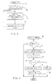
- the stall current I s of the DC torque motor 30 is measured as illustrated in Figure 4.
- This routine is entered at point 58 and proceeds to a step 60 at which a complete flag is sampled. A set condition of this flag indicates that the motor stall current has been identified. If reset, indicating that the stall current has not yet been determined, the program proceeds to a step 62 where the motor electromagnetic brake is deenergized to apply the brake to prevent rotation of the torque motor 30 and system voltage (such as the battery 52 voltage) is applied to the DC motor 30 by commanding a high current value. The motor current then begins to increase rapidly to the motor stall current, which is determined by the motor resistance and the system voltage.
- a counter is incremented, after which the state of the counter is compared to a predetermined count, such as four, at step 66. If not equal to this count, the program proceeds to a step 68 where the motor current I m is read and stored.
- step 66 determines that four samples of the motor current have been monitored and stored.
- step 70 the complete flag is set at step 70 after which the stall current I s of the motor 30 is determined at step 71.
- the stall current may simply comprise the last stored value of motor current at step 68 or, in another embodiment, may comprise an average of the four motor currents stored at step 68.
- the result of step 71 is a measurement of the stall current I s of the motor 30.
- the program then proceeds to a step 72 where the anti-lock brake control routine is performed to provide anti-lock brake control functions as required.
- This routine is of conventional form and may include the sensing of the wheel speed to determine whether or not the wheel is about to lock. If sensed, the torque motor 30 is then controlled to retract the piston 38 to reduce the pressure so as to prevent wheel lock, after which the pressure is modulated to maintain stable braking. Further, this routine provides for adjusting the modulator 18 to position the piston 38 in its fully extended position, following anti-lock controlled braking, so as to reset the braking system for normal braking. This resetting function provides for controlling the speed of the DC torque motor 30 to prevent damage to the modulator 18 when the piston reaches its end of travel.
- step 72 the program proceeds to perform background tasks at step 73. These tasks may include other vehicle functions and also diagnostic routines.
- the steps 72 and 73 are repeated at constant time intervals. This is provided by the microprocessor 46 which generates a time interrupt at repeated intervals, such as 5 milliseconds. Upon the generation of the interrupts, the routines 58 and 60 are also repeated.
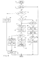
- FIG. 5 there is illustrated the reset routine executed at the end of anti-lock controlled braking to reposition the piston 38 so as to enable the system to carry out normal braking, and to be ready for subsequent anti-lock controlled braking.
- the reset routine of Figure 5 may also be executed during the initialization routine 56, or when the vehicle speed first exceeds a predetermined low threshold when the vehicle is first operated. This then assures that when the system is first powered-up, the piston 38 is fully extended.
- the routine of Figure 5 provides for the control of the DC torque motor 12 to move the piston 38 to its extended position at a controlled speed.
- the reset routine applies the stall current I s , resulting in the application of an appropriate system voltage to the DC torque motor 30.
- the current through the torque motor 30 rapidly rises to the stall current level since the motor is initially at rest and due to the motor/actuator time constant.
- the motor speed then begins to increase from zero at a rate that is a function of the difference between the torque output of the DC motor 30 and its load established by the brake pressure at the head of the piston 38.
- the acceleration of the motor 30, and therefore the rate of decrease of the motor current is a function of the difference between the motor torque and the load on the motor represented by the hydraulic pressure at the head of the piston 38.
- Stall current is continually applied with the resulting full system voltage applied to the motor 30, until the motor current decreases below the stall current by a predetermined amount representing a predetermined motor speed.
- the predetermined amount is a calibration constant K i stored in the read-only memory of the microprocessor 46.
- the time required for the motor current to decrease to this level is a direct function of the acceleration of the motor, and therefore a direct function of the load on the motor 30.
- the motor current command is set to zero for a wait time that is inversely proportional to the time required for the motor current to decrease by the predetermined amount K i below the stall current I s . Accordingly, as the time required for the motor to accelerate to the predetermined speed increases, the wait time during which zero motor current is commanded decreases. In the preferred embodiment, the sum of the two times (time of application of motor current + wait time) is a constant cycle period. Upon termination of the wait time, the routine is repeated until such time as the routine determines that the piston 38 has returned to its extended position.
- the reset routine is entered at step 74 and proceeds to a step 76 to determine whether or not the reset routine has been completed. If not, the condition of a first loop flag is sampled at 78. This flag is utilized to assure that motor stall current is commanded for the interval required for the motor current to increase to the stall current. In this embodiment, the time of one interrupt interval is adequate to assure the motor current reaches this level.
- the program proceeds to a step 80 where the first loop flag is cleared, after which the stall current I s identified in the routine of Figure 4 is commanded at step 82. Thereafter, the program exits the reset routine.
- the time required for the motor current to achieve substantially the stall current is less than the interrupt time interval so that the next time the reset routine of Figure 5 is executed, the motor current had reached the stall current value.
- step 78 if the first loop flag is reset indicating that the motor current had previously reached the stall current, the program executes a series of steps which times the first portion of the motor current control cycle during which stall current is commanded and determines if the reset procedure has been completed.
- This series of steps begins at step 84 to determine whether the speed of the motor 30 represented by the drop in motor current from the stall current is greater than a predetermined value corresponding to a decrease K i in the motor current from the stall current I s .
- K i may be a calibration constant representing a predetermined motor speed condition. In other embodiments, K i may be adjusted to provide for a variable speed control of the torque motor 30.
- a wait period flag is sampled. This flag is initially reset during the initialization routine 56 of Figure 3 and is set, as will be described, when the motor current first decreases from the stall motor current by the amount K i . Assuming that this condition has not yet been met, the program then proceeds to step 88 where a cycle timer is decremented. The initial count of the cycle timer is initially established as a calibration constant value K t which represents the time of the motor current control cycle.
- a home timer is decremented.
- the initial value of the home timer represents a maximum time required for the motor to reset under all motor load conditions while the motor current command is equal to the stall current.
- the value of the home timer is compared to zero at step 92 to determine whether or not the reset routine is complete. If the value of the home timer has not reached zero, the program exits the routine.
- step 98 determines the cycle timer count is greater than zero, the wait period flag is set at step 100, after which the motor current commanded is set to zero at step 102.
- the steps 94 to 102 are repeated as long as I s -I m is greater than K i , and until the expiration of the wait time corresponding to the expiration of the cycle time.
- This condition is sensed at step 98 after which a new motor current control cycle is initiated by resetting the wait period flag at step 104 and initializing the cycle timer to the initial value K t at step 106. Thereafter, the current commanded is set at the stall current value I s at step 82 and the aforementioned motor current control cycle is repeated.
- the average motor torque is established at a level that is adaptive to the load on the head of the piston 38 to control the motor speed during the reset routine.
- the maximum stall current I s is commanded for greater periods of time with a resulting decrease in the wait time during which zero current is commanded. If the motor load is such that the motor speed never increases to the value corresponding to the current drop K i from the stall current I s , maximum current will continuously be commanded to the motor 34 resulting in continuous application of system voltage to the motor 30.
- the reset routine of Figure 5 will repeatedly proceed from step 84 through the steps 86 to 92 until such time that the value of the home timer reaches zero, as sensed at step 92, indicating that the resetting of the actuator 18 is complete. Thereafter, at step 110, the reset complete flag is set. Subsequent executions of the reset routine results in the reset steps being bypassed via step 76.
- the foregoing routine may provide for variable speed control of the torque motor 30.
- the value of K i may be made a variable and controlled to varying levels to adjust the average motor torque output.
- the total control cycle time K t may be adjusted so as to increase or decrease the rest period provided during each of the motor control cycles.
- Each of these variables may be controlled to provide for controlled speed of the torque motor 30. In all cases, the control adapts to the variable load on the torque motor 30.
Landscapes
- Engineering & Computer Science (AREA)
- Physics & Mathematics (AREA)
- Fluid Mechanics (AREA)
- Transportation (AREA)
- Mechanical Engineering (AREA)
- Regulating Braking Force (AREA)
- Control Of Electric Motors In General (AREA)
Applications Claiming Priority (2)
| Application Number | Priority Date | Filing Date | Title |
|---|---|---|---|
| US07/495,881 US4969756A (en) | 1990-03-19 | 1990-03-19 | Motor driven actuator speed control |
| US495881 | 1995-06-28 |
Publications (2)
| Publication Number | Publication Date |
|---|---|
| EP0448145A2 true EP0448145A2 (fr) | 1991-09-25 |
| EP0448145A3 EP0448145A3 (en) | 1993-01-07 |
Family
ID=23970369
Family Applications (1)
| Application Number | Title | Priority Date | Filing Date |
|---|---|---|---|
| EP19910200471 Withdrawn EP0448145A3 (en) | 1990-03-19 | 1991-03-05 | Method of controlling the speed of a motor |
Country Status (3)
| Country | Link |
|---|---|
| US (1) | US4969756A (fr) |
| EP (1) | EP0448145A3 (fr) |
| JP (1) | JPH04222492A (fr) |
Families Citing this family (27)
| Publication number | Priority date | Publication date | Assignee | Title |
|---|---|---|---|---|
| SE8803756D0 (sv) * | 1988-10-20 | 1988-10-20 | Acg-Nystroem Ab | Fjaerrkontroll av maskinfunktioner med fotpedaler eller blaasmunstycke |
| US5112116A (en) * | 1989-05-17 | 1992-05-12 | General Motors Corporation | Anti-lock braking system with electromagnetic brake |
| US4969756A (en) * | 1990-03-19 | 1990-11-13 | General Motors Corporation | Motor driven actuator speed control |
| NZ280025A (en) * | 1990-12-19 | 1997-12-19 | Fisher & Paykel | Speed control of multiphase electronically controlled motor |
| US5297857A (en) * | 1991-05-31 | 1994-03-29 | Allied-Signal Inc. | Direct acting electro-hydraulic braking system with regulated leak rate |
| US5385394A (en) * | 1993-05-11 | 1995-01-31 | General Motors Corporation | Antilock brake system with controlled pressure augmentation |
| US5894208A (en) * | 1995-07-28 | 1999-04-13 | Eaton Corporation | Control for electrically actuated shifting mechanism |
| US5646848A (en) * | 1995-08-09 | 1997-07-08 | General Motors Corporation | Method for proportionally controlling the brakes of a vehicle based on tire deformation |
| US5646849A (en) * | 1995-08-09 | 1997-07-08 | General Motors Corporation | Method for proportionally controlling the brakes of a vehicle based on front and rear wheel speeds |
| US5511859A (en) * | 1995-08-25 | 1996-04-30 | General Motors Corporation | Regenerative and friction brake blend control |
| US6513886B1 (en) | 1996-05-07 | 2003-02-04 | General Motors Corporation | Brake system control in which update of wheel speed normalization factors is selectively inhibited |
| US5838124A (en) * | 1997-08-28 | 1998-11-17 | Barber Colman | Systems and methods for braking of actuator and brushless DC motor therein |
| US5872434A (en) * | 1997-08-28 | 1999-02-16 | Barber Colman Company | Systems and methods for actuator power failure response |
| US5847530A (en) * | 1997-08-28 | 1998-12-08 | Barber Colman | Systems and methods for torque control of actuator and brushless DC motor therein |
| US6593716B1 (en) * | 2000-11-21 | 2003-07-15 | Honeywell International Inc. | Circuit using current limiting to reduce power consumption of actuator with DC brush motor |
| US6670783B2 (en) | 2001-10-31 | 2003-12-30 | Pelco | Method and apparatus for improved motor control through current/velocity correction |
| US7180255B2 (en) * | 2005-01-26 | 2007-02-20 | Delphi Technologies, Inc. | Controlling the release of a brush motor which has applied a load |
| TWI274468B (en) * | 2005-05-04 | 2007-02-21 | Sunplus Technology Co Ltd | Brake system and method for a direct current brushed motor without a hall sensor |
| US8727740B2 (en) | 2007-01-05 | 2014-05-20 | Schlumberger Technology Corporation | Cylinder assembly for providing uniform flow output |
| JP4902373B2 (ja) * | 2007-01-30 | 2012-03-21 | 本田技研工業株式会社 | ブレーキ装置およびブレーキ装置の制御方法 |
| US8084982B2 (en) | 2008-11-18 | 2011-12-27 | Honeywell International Inc. | HVAC actuator with output torque compensation |
| US9222618B2 (en) | 2010-11-29 | 2015-12-29 | Lincoln Industrial Corporation | Stepper motor driving a lubrication pump providing uninterrupted lubricant flow |
| US9388940B2 (en) | 2010-11-29 | 2016-07-12 | Lincoln Industrial Corporation | Variable speed stepper motor driving a lubrication pump system |
| US9022177B2 (en) | 2010-11-29 | 2015-05-05 | Lincoln Industrial Corporation | Pump having stepper motor and overdrive control |
| US9671065B2 (en) | 2013-10-17 | 2017-06-06 | Lincoln Industrial Corporation | Pump having wear and wear rate detection |
| DE102018212991A1 (de) * | 2018-08-03 | 2020-02-06 | Robert Bosch Gmbh | Verfahren zum Betreiben eines bürstenlosen Gleichstrommotors |
| AU2022297526A1 (en) * | 2021-06-23 | 2024-02-08 | Outrider Technologies, Inc. | Motor stall and trailer lift |
Family Cites Families (8)
| Publication number | Priority date | Publication date | Assignee | Title |
|---|---|---|---|---|
| GB1531490A (en) * | 1975-12-24 | 1978-11-08 | Cableform Ltd | Pulse controllers for series motors |
| JPS6043756B2 (ja) * | 1976-06-21 | 1985-09-30 | 三菱電機株式会社 | 回転制御装置 |
| JPS5745232A (en) * | 1980-08-29 | 1982-03-15 | Matsushita Electric Ind Co Ltd | Device and method for developing |
| DE3119808C2 (de) * | 1981-05-19 | 1986-11-27 | Willy Scheuerle Fahrzeugfabrik GmbH & Co, 7114 Pfedelbach | Steuereinrichtung für hydrostatisches Getriebe |
| JPS6159068A (ja) * | 1984-08-30 | 1986-03-26 | Arai Pump Mfg Co Ltd | シ−ル装置およびその製作方法 |
| JPS63302794A (ja) * | 1987-05-30 | 1988-12-09 | Fujitsu Ltd | モ−タ電流制御方式 |
| US4835695A (en) * | 1987-11-13 | 1989-05-30 | General Motors Corporation | Add-on vehicle wheel slip controller |
| US4969756A (en) * | 1990-03-19 | 1990-11-13 | General Motors Corporation | Motor driven actuator speed control |
-
1990
- 1990-03-19 US US07/495,881 patent/US4969756A/en not_active Expired - Fee Related
-
1991
- 1991-03-05 EP EP19910200471 patent/EP0448145A3/en not_active Withdrawn
- 1991-03-19 JP JP3054433A patent/JPH04222492A/ja active Pending
Also Published As
| Publication number | Publication date |
|---|---|
| JPH04222492A (ja) | 1992-08-12 |
| US4969756A (en) | 1990-11-13 |
| EP0448145A3 (en) | 1993-01-07 |
Similar Documents
| Publication | Publication Date | Title |
|---|---|---|
| EP0448145A2 (fr) | Méthode pour commander la vitesse d'un moteur | |
| EP0397328B1 (fr) | Appareil et procédé de commande d'entraînement de véhicule | |
| CA1246716A (fr) | Systeme anti-blocage des freins | |
| CA2010642C (fr) | Systeme anti-patinage adaptatif pour freins abs | |
| US5320421A (en) | Motor driven brake pressure modulator with motor position control | |
| JPH0771929B2 (ja) | 車輪スリップ制御装置及び方法 | |
| EP0397330B1 (fr) | Procédé de commande d'entraînement de véhicule | |
| US5281009A (en) | Antilock brake system with closed loop control of hold during release | |
| US4750124A (en) | Anti-lock brake control system | |
| US5071199A (en) | Antilock brake system with motor current control | |
| US5454630A (en) | Automotive antilock braking | |
| EP0936116B1 (fr) | Systèmes et méthodes de commande de freinage | |
| EP0489451B1 (fr) | Système de réglage antiblocage avec un moyen de commande du courant du moteur | |
| US5273349A (en) | Antilock brake system with motor current control | |
| US4783127A (en) | Anti-lock brake control system | |
| US4755946A (en) | Motor actuated anti-lock brake control system | |
| EP0470657A2 (fr) | Procédé de commande de freinage à antiblocage à commande de relâchement pas à pas | |
| CA1318378C (fr) | Commande de dispositif anti-blocage a moteur couple c.c. | |
| EP0459548B1 (fr) | Méthode et appareil pour commander la pression de freinage appliquée à un frein de véhicule | |
| US5308153A (en) | Antilock brake system with closed loop apply bump | |
| US5385394A (en) | Antilock brake system with controlled pressure augmentation | |
| US5080447A (en) | Antilock brake controller with brake mode filter | |
| US4989921A (en) | Mine hoist brake regulator | |
| USRE33557E (en) | Anti-lock brake control system |
Legal Events
| Date | Code | Title | Description |
|---|---|---|---|
| PUAI | Public reference made under article 153(3) epc to a published international application that has entered the european phase |
Free format text: ORIGINAL CODE: 0009012 |
|
| AK | Designated contracting states |
Kind code of ref document: A2 Designated state(s): DE FR GB IT |
|
| PUAL | Search report despatched |
Free format text: ORIGINAL CODE: 0009013 |
|
| AK | Designated contracting states |
Kind code of ref document: A3 Designated state(s): DE FR GB IT |
|
| 17P | Request for examination filed |
Effective date: 19930121 |
|
| 17Q | First examination report despatched |
Effective date: 19940601 |
|
| STAA | Information on the status of an ep patent application or granted ep patent |
Free format text: STATUS: THE APPLICATION HAS BEEN WITHDRAWN |
|
| 18W | Application withdrawn |
Withdrawal date: 19940726 |