EP0448421A1 - Ventil-Steuervorrichtung mit optischer Detektion - Google Patents
Ventil-Steuervorrichtung mit optischer Detektion Download PDFInfo
- Publication number
- EP0448421A1 EP0448421A1 EP91400392A EP91400392A EP0448421A1 EP 0448421 A1 EP0448421 A1 EP 0448421A1 EP 91400392 A EP91400392 A EP 91400392A EP 91400392 A EP91400392 A EP 91400392A EP 0448421 A1 EP0448421 A1 EP 0448421A1
- Authority
- EP
- European Patent Office
- Prior art keywords
- receiver
- transmitter
- axes
- axis
- control device
- Prior art date
- Legal status (The legal status is an assumption and is not a legal conclusion. Google has not performed a legal analysis and makes no representation as to the accuracy of the status listed.)
- Granted
Links
Images

Classifications
-
- E—FIXED CONSTRUCTIONS
- E03—WATER SUPPLY; SEWERAGE
- E03C—DOMESTIC PLUMBING INSTALLATIONS FOR FRESH WATER OR WASTE WATER; SINKS
- E03C1/00—Domestic plumbing installations for fresh water or waste water; Sinks
- E03C1/02—Plumbing installations for fresh water
- E03C1/05—Arrangements of devices on wash-basins, baths, sinks, or the like for remote control of taps
- E03C1/055—Electrical control devices, e.g. with push buttons, control panels or the like
- E03C1/057—Electrical control devices, e.g. with push buttons, control panels or the like touchless, i.e. using sensors
Definitions
- the present invention relates to a device for controlling a tap by optical detection.
- Devices are known according to which the presence of the user's hands or body is detected using an opto-electronic system which triggers the flow of water, the flow being stopped by move it away from the user.
- the detection device is produced by a transmitter producing, for example, an infrared ray which is reflected by the hands or the body of the user towards a receiver sensitive to the ray emitted and which then delivers a signal, the latter being amplified and processed to allow control of a solenoid valve.
- the transmitter and the receiver are physically very close and the incident ray is practically reflected on itself. Therefore, the detection area is very small and it is located under the spout of the tap. Under these conditions, it is not possible to maintain the flow of water if the hands come out of this area and plunge, for example, towards the bottom of the sink.
- the present invention which overcomes these drawbacks, is remarkable in that the transmitter and the receiver are separate and in that their axes are concurrent and contained in an inclined plane.
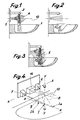
- 1 is a sink comprising a spout 2 for supplying water placed under the control of a detection unit 3.
- the detection zone 5 extends practically from the spout 2 to the bottom of the sink.
- the axes 8 and 9 are concurrent and contained in an inclined plane which lowers towards the bottom of the sink relative to the horizontal XX, the point of convergence I being located, substantially, on the vertical YY passing through the axis of the spout 2.
- a lens is placed in front of the radiating semiconductor element constituting the emitter, the axis of the lens is coincident with that of said element and practically the central emerging ray, that of Figures 1 and 4 , is perpendicular to the partition supporting the device.
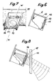
- the central emerging ray, materialized by the axis 8, must be deflected towards the center. This result is obtained by shifting the optical axis of the lens 11 relative to that of the emitter 6. A analogous but symmetrical arrangement is adopted with regard to the receiver.
- the optical axes of the transmitter and the receiver are inclined as shown in FIGS. 7 to 8.
- a prism is placed in front of the lenses 11 Fresnel 12, made of a material allowing the infrared to pass through,
- Fresnel 12 made of a material allowing the infrared to pass through
- a plurality of prisms is used, the assembly thus constituted being able to serve as a protector for the device, the prism (s) 12 making it possible to widen the beam downwards the vertical plane.
- the device which has just been described must be able to be used whatever the distances between the spout 2 and the support wall on the one hand, and said spout and the bottom of the sink on the other hand. In other words, it is necessary to be able to vary the position of the point I where the axes 8 and 9 meet, and this, preferably, along a horizontal ZZ.
- each lens can be moved in a vertical direction and in a horizontal direction relative to the element in front of which it is placed.
- each lens 11 is carried by a slide 13 guided in a slide 14 of the housing 15 containing the transmitter or the receiver, the axis WW of the slide being inclined relative to the plane of symmetry of the device, which contains the YY axis.
- each slide allows a double adjustment.
- the meeting point I of the axes 8 and 9 is in Ia, that is to say further than that I on the same horizontal ZZ.
- the meeting point is in Ib, that is to say less far than that I on the same horizontal ZZ.
- the invention provides for associating a usual device with that of the invention, as is apparent from FIGS. 4 and 5.
- the usual device detects the zone located immediately in below the spout 2.
- the usual device 16 is arranged between the transmitter 6 and the receiver 7.
Landscapes
- Life Sciences & Earth Sciences (AREA)
- Engineering & Computer Science (AREA)
- Hydrology & Water Resources (AREA)
- Public Health (AREA)
- Water Supply & Treatment (AREA)
- Health & Medical Sciences (AREA)
- Geophysics And Detection Of Objects (AREA)
- Undergarments, Swaddling Clothes, Handkerchiefs Or Underwear Materials (AREA)
- Optical Communication System (AREA)
- Domestic Plumbing Installations (AREA)
- Indication Of The Valve Opening Or Closing Status (AREA)
- Semiconductor Lasers (AREA)
- Lasers (AREA)
Applications Claiming Priority (2)
| Application Number | Priority Date | Filing Date | Title |
|---|---|---|---|
| FR9003716 | 1990-03-23 | ||
| FR9003716A FR2660044B1 (fr) | 1990-03-23 | 1990-03-23 | Dispositif de commande d'un robinet par detection optique. |
Publications (2)
| Publication Number | Publication Date |
|---|---|
| EP0448421A1 true EP0448421A1 (de) | 1991-09-25 |
| EP0448421B1 EP0448421B1 (de) | 1994-08-31 |
Family
ID=9395029
Family Applications (1)
| Application Number | Title | Priority Date | Filing Date |
|---|---|---|---|
| EP91400392A Expired - Lifetime EP0448421B1 (de) | 1990-03-23 | 1991-02-15 | Ventil-Steuervorrichtung mit optischer Detektion |
Country Status (5)
| Country | Link |
|---|---|
| EP (1) | EP0448421B1 (de) |
| AT (1) | ATE110832T1 (de) |
| DE (1) | DE69103657T2 (de) |
| ES (1) | ES2060312T3 (de) |
| FR (1) | FR2660044B1 (de) |
Cited By (6)
| Publication number | Priority date | Publication date | Assignee | Title |
|---|---|---|---|---|
| EP0583785A1 (de) * | 1992-08-20 | 1994-02-23 | von Lepel, Freifrau, Barbara | Auslaufarmatur mit Näherungssensor |
| EP0623710A1 (de) * | 1993-05-07 | 1994-11-09 | SCHROTT, Harald | Berührungslos betätigbare Sanitärarmatur |
| US6192530B1 (en) * | 1999-05-17 | 2001-02-27 | Wen S. Dai | Automatic faucet |
| US20100308224A1 (en) * | 2008-01-29 | 2010-12-09 | Weigen Chen | Infrared sensing device |
| CN106051290A (zh) * | 2016-07-25 | 2016-10-26 | 无锡昊瑜节能环保设备有限公司 | 水龙头的出水控制方法 |
| CN106195390A (zh) * | 2016-07-25 | 2016-12-07 | 无锡昊瑜节能环保设备有限公司 | 一种水龙头出水控制方法 |
Citations (4)
| Publication number | Priority date | Publication date | Assignee | Title |
|---|---|---|---|---|
| GB2195763A (en) * | 1986-09-13 | 1988-04-13 | Theodoros Mastichiadis | Water tap |
| US4767922A (en) * | 1986-08-25 | 1988-08-30 | Honeywell Inc. | Hand presence activated water faucet controller |
| US4823414A (en) * | 1986-01-22 | 1989-04-25 | Water-Matic Corporation | Automatic faucet-sink control system |
| EP0347527A1 (de) * | 1988-03-28 | 1989-12-27 | Sloan Valve Company | Automatisch gesteuerter Wasserhahn |
-
1990
- 1990-03-23 FR FR9003716A patent/FR2660044B1/fr not_active Expired - Lifetime
-
1991
- 1991-02-15 EP EP91400392A patent/EP0448421B1/de not_active Expired - Lifetime
- 1991-02-15 DE DE69103657T patent/DE69103657T2/de not_active Expired - Fee Related
- 1991-02-15 ES ES91400392T patent/ES2060312T3/es not_active Expired - Lifetime
- 1991-02-15 AT AT91400392T patent/ATE110832T1/de not_active IP Right Cessation
Patent Citations (4)
| Publication number | Priority date | Publication date | Assignee | Title |
|---|---|---|---|---|
| US4823414A (en) * | 1986-01-22 | 1989-04-25 | Water-Matic Corporation | Automatic faucet-sink control system |
| US4767922A (en) * | 1986-08-25 | 1988-08-30 | Honeywell Inc. | Hand presence activated water faucet controller |
| GB2195763A (en) * | 1986-09-13 | 1988-04-13 | Theodoros Mastichiadis | Water tap |
| EP0347527A1 (de) * | 1988-03-28 | 1989-12-27 | Sloan Valve Company | Automatisch gesteuerter Wasserhahn |
Cited By (8)
| Publication number | Priority date | Publication date | Assignee | Title |
|---|---|---|---|---|
| EP0583785A1 (de) * | 1992-08-20 | 1994-02-23 | von Lepel, Freifrau, Barbara | Auslaufarmatur mit Näherungssensor |
| EP0623710A1 (de) * | 1993-05-07 | 1994-11-09 | SCHROTT, Harald | Berührungslos betätigbare Sanitärarmatur |
| US6192530B1 (en) * | 1999-05-17 | 2001-02-27 | Wen S. Dai | Automatic faucet |
| US20100308224A1 (en) * | 2008-01-29 | 2010-12-09 | Weigen Chen | Infrared sensing device |
| EP2236880A4 (de) * | 2008-01-29 | 2011-01-12 | Shanghai Kohler Electronics | Infrarotinduktionsvorrichtung |
| US8421020B2 (en) * | 2008-01-29 | 2013-04-16 | Shanghai Kohler Electronics, Ltd. | Infrared sensing device |
| CN106051290A (zh) * | 2016-07-25 | 2016-10-26 | 无锡昊瑜节能环保设备有限公司 | 水龙头的出水控制方法 |
| CN106195390A (zh) * | 2016-07-25 | 2016-12-07 | 无锡昊瑜节能环保设备有限公司 | 一种水龙头出水控制方法 |
Also Published As
| Publication number | Publication date |
|---|---|
| DE69103657T2 (de) | 1995-03-23 |
| DE69103657D1 (de) | 1994-10-06 |
| ES2060312T3 (es) | 1994-11-16 |
| FR2660044A1 (fr) | 1991-09-27 |
| FR2660044B1 (fr) | 1992-08-14 |
| ATE110832T1 (de) | 1994-09-15 |
| EP0448421B1 (de) | 1994-08-31 |
Similar Documents
| Publication | Publication Date | Title |
|---|---|---|
| US6127671A (en) | Directional object sensor for automatic flow controller | |
| EP0224437B1 (de) | Optische Vorrichtung mit Lichtbündel zur automatischen Kontrolle der Biegeoperation beim Biegen mit einer Abkantpresse | |
| WO1998048370A1 (fr) | Dispositif optoelectronique d'acquisition d'images, notamment de codes a barres | |
| EP1193773A3 (de) | Optische Vorrichtung für eine optischesElement und diese Vorrichtung verwendendes Gerät | |
| FR2995977A1 (fr) | Guide de lumiere pour un dispositif d'eclairage et/ou de signalisation de vehicule automobile | |
| FR2772115A1 (fr) | Illuminateur de surface | |
| US5773819A (en) | Single element light detector | |
| EP0448421B1 (de) | Ventil-Steuervorrichtung mit optischer Detektion | |
| KR890002840A (ko) | 광학 픽업장치 | |
| KR101852827B1 (ko) | 진공 청소기 | |
| EP0567357B1 (de) | Leuchtender Druckknopf-Schalter mit kanalisiertem und gestreutem Lichtflux | |
| JP5828073B2 (ja) | 赤外線センサ | |
| EP3002155A2 (de) | Beleuchtungsvorrichtung für einen innenraum eines kraftfahrzeugs | |
| KR970706556A (ko) | 광학적인 주화 센싱 스테이션(optical coin sensing station) | |
| CH621001A5 (de) | ||
| US9104268B2 (en) | Compact optical finger navigation system with illumination via redirection surface holes | |
| EP0736415B1 (de) | Beleuchtungseinrichtung für Anzeigeinstrumente in einem Armaturenbrett | |
| US20060278815A1 (en) | Regressive reflection type photoelectric switch | |
| JPH10227635A (ja) | 傾斜センサ | |
| JP3278921B2 (ja) | 光電スイッチ | |
| JP6315428B2 (ja) | 自動水栓装置 | |
| EP1286436A3 (de) | Wellenlängenkontrollgerät und laser modul | |
| FR2995969A1 (fr) | Systeme optique de vehicule automobile comprenant une nappe de guidage de lumiere | |
| EP4303837A1 (de) | Kontaktlose biometrische fingerabdruckerfassungsvorrichtung | |
| JP2006155964A (ja) | 表示装置のバックライト |
Legal Events
| Date | Code | Title | Description |
|---|---|---|---|
| PUAI | Public reference made under article 153(3) epc to a published international application that has entered the european phase |
Free format text: ORIGINAL CODE: 0009012 |
|
| 17P | Request for examination filed |
Effective date: 19910510 |
|
| AK | Designated contracting states |
Kind code of ref document: A1 Designated state(s): AT BE CH DE DK ES FR GB GR IT LI LU NL SE |
|
| 17Q | First examination report despatched |
Effective date: 19930222 |
|
| GRAA | (expected) grant |
Free format text: ORIGINAL CODE: 0009210 |
|
| AK | Designated contracting states |
Kind code of ref document: B1 Designated state(s): AT BE CH DE DK ES FR GB GR IT LI LU NL SE |
|
| PG25 | Lapsed in a contracting state [announced via postgrant information from national office to epo] |
Ref country code: NL Effective date: 19940831 Ref country code: GR Free format text: LAPSE BECAUSE OF FAILURE TO SUBMIT A TRANSLATION OF THE DESCRIPTION OR TO PAY THE FEE WITHIN THE PRESCRIBED TIME-LIMIT Effective date: 19940831 Ref country code: GB Effective date: 19940831 Ref country code: DK Effective date: 19940831 |
|
| REF | Corresponds to: |
Ref document number: 110832 Country of ref document: AT Date of ref document: 19940915 Kind code of ref document: T |
|
| ITF | It: translation for a ep patent filed | ||
| REF | Corresponds to: |
Ref document number: 69103657 Country of ref document: DE Date of ref document: 19941006 |
|
| REG | Reference to a national code |
Ref country code: ES Ref legal event code: FG2A Ref document number: 2060312 Country of ref document: ES Kind code of ref document: T3 |
|
| PG25 | Lapsed in a contracting state [announced via postgrant information from national office to epo] |
Ref country code: SE Effective date: 19941130 |
|
| NLV1 | Nl: lapsed or annulled due to failure to fulfill the requirements of art. 29p and 29m of the patents act | ||
| PG25 | Lapsed in a contracting state [announced via postgrant information from national office to epo] |
Ref country code: LU Free format text: LAPSE BECAUSE OF NON-PAYMENT OF DUE FEES Effective date: 19950228 Ref country code: LI Effective date: 19950228 Ref country code: CH Effective date: 19950228 Ref country code: BE Effective date: 19950228 |
|
| GBV | Gb: ep patent (uk) treated as always having been void in accordance with gb section 77(7)/1977 [no translation filed] |
Effective date: 19940831 |
|
| PLBE | No opposition filed within time limit |
Free format text: ORIGINAL CODE: 0009261 |
|
| STAA | Information on the status of an ep patent application or granted ep patent |
Free format text: STATUS: NO OPPOSITION FILED WITHIN TIME LIMIT |
|
| 26N | No opposition filed | ||
| BERE | Be: lapsed |
Owner name: LES ROBINETS PRESTO Effective date: 19950228 |
|
| ITTA | It: last paid annual fee | ||
| PGFP | Annual fee paid to national office [announced via postgrant information from national office to epo] |
Ref country code: ES Payment date: 19990225 Year of fee payment: 9 |
|
| PGFP | Annual fee paid to national office [announced via postgrant information from national office to epo] |
Ref country code: FR Payment date: 19990226 Year of fee payment: 9 |
|
| PGFP | Annual fee paid to national office [announced via postgrant information from national office to epo] |
Ref country code: AT Payment date: 19990228 Year of fee payment: 9 |
|
| PGFP | Annual fee paid to national office [announced via postgrant information from national office to epo] |
Ref country code: DE Payment date: 19990429 Year of fee payment: 9 |
|
| PG25 | Lapsed in a contracting state [announced via postgrant information from national office to epo] |
Ref country code: AT Free format text: LAPSE BECAUSE OF NON-PAYMENT OF DUE FEES Effective date: 20000215 |
|
| PG25 | Lapsed in a contracting state [announced via postgrant information from national office to epo] |
Ref country code: ES Free format text: LAPSE BECAUSE OF NON-PAYMENT OF DUE FEES Effective date: 20000216 |
|
| PG25 | Lapsed in a contracting state [announced via postgrant information from national office to epo] |
Ref country code: FR Free format text: LAPSE BECAUSE OF NON-PAYMENT OF DUE FEES Effective date: 20001031 |
|
| PG25 | Lapsed in a contracting state [announced via postgrant information from national office to epo] |
Ref country code: DE Free format text: LAPSE BECAUSE OF NON-PAYMENT OF DUE FEES Effective date: 20001201 |
|
| REG | Reference to a national code |
Ref country code: FR Ref legal event code: ST |
|
| REG | Reference to a national code |
Ref country code: ES Ref legal event code: FD2A Effective date: 20011010 |
|
| PG25 | Lapsed in a contracting state [announced via postgrant information from national office to epo] |
Ref country code: IT Free format text: LAPSE BECAUSE OF NON-PAYMENT OF DUE FEES Effective date: 20050215 |