EP0448820A1 - Paroi de séparation pour douche avec panneau ajustable - Google Patents
Paroi de séparation pour douche avec panneau ajustable Download PDFInfo
- Publication number
- EP0448820A1 EP0448820A1 EP90124815A EP90124815A EP0448820A1 EP 0448820 A1 EP0448820 A1 EP 0448820A1 EP 90124815 A EP90124815 A EP 90124815A EP 90124815 A EP90124815 A EP 90124815A EP 0448820 A1 EP0448820 A1 EP 0448820A1
- Authority
- EP
- European Patent Office
- Prior art keywords
- wall part
- edge
- fixed wall
- fixed
- partition
- Prior art date
- Legal status (The legal status is an assumption and is not a legal conclusion. Google has not performed a legal analysis and makes no representation as to the accuracy of the status listed.)
- Granted
Links
Images




Classifications
-
- A—HUMAN NECESSITIES
- A47—FURNITURE; DOMESTIC ARTICLES OR APPLIANCES; COFFEE MILLS; SPICE MILLS; SUCTION CLEANERS IN GENERAL
- A47K—SANITARY EQUIPMENT; ACCESSORIES THEREFOR, e.g. TOILET ACCESSORIES
- A47K3/00—Baths; Showers; Appurtenances therefor
- A47K3/28—Showers or bathing douches
- A47K3/30—Screens or collapsible cabinets for showers or baths
- A47K3/36—Articulated screens
-
- A—HUMAN NECESSITIES
- A47—FURNITURE; DOMESTIC ARTICLES OR APPLIANCES; COFFEE MILLS; SPICE MILLS; SUCTION CLEANERS IN GENERAL
- A47K—SANITARY EQUIPMENT; ACCESSORIES THEREFOR, e.g. TOILET ACCESSORIES
- A47K3/00—Baths; Showers; Appurtenances therefor
- A47K3/28—Showers or bathing douches
- A47K3/30—Screens or collapsible cabinets for showers or baths
- A47K2003/307—Adjustable connections to the wall
Definitions
- the invention relates to a partition for shower with at least one fixed wall part and a door, the wall part being anchored and adjustable in its position of use.
- the door can be a sliding door, a swing door or a folding door. It is also possible that this door is arranged in the plane or parallel to the plane of the fixed wall part or at an angle to it.
- the invention is based on the object, a door supporting or cooperating with it a fixed wall part of a partition for shower of the type mentioned on its free, a building wall and / or its anchoring To make the area adjustable and adjustable independently of any setting means of its anchoring.
- an adjusting element for bending and pivoting the free edge facing away from the anchoring point engages in an approximately horizontal direction on the upper and / or lower edge of the fixed wall part at a distance from its edge or wall anchoring.
- Plate-shaped wall parts even if they are made entirely or almost exclusively of glass, are known to be elastically bendable to a certain extent, which the invention makes use of for such fixed wall parts of partition walls for showers.
- the attached and anchored wall part can also be subsequently adjusted with the help of the adjusting elements according to the invention on the free edge facing away from the anchoring point, so that, for example, an adaptation of this free edge to an associated door element is possible, or an escape due to on-site tolerances or installation errors or Alignment of the fixed wall part can be made subsequently by bending this wall part with respect to its edge facing away from the anchoring with the aid of the adjusting element into the desired position and holding it there.
- An expedient and advantageous embodiment of the invention which can simultaneously improve the anchoring of the fixed wall part, may consist in that the free arm of a pivoting or pushing lever engages at the upper edge of the fixed wall part of the partition, which free arm in the horizontal direction transverse to
- the longitudinal extent of the upper, approximately horizontal edge is adjustable and fixable and via a fastening element, preferably a fork or a cross-over the upper edge of the fixed wall part Flange transmits the adjustment movement to the fixed wall part of the partition.
- the lower, approximately horizontal edge of the fixed wall part can be encompassed or acted upon by, in particular, an approximately fork-shaped adjusting element, the projections of which can be adjusted transversely to the plane formed by the fixed wall part, taking along the detected edge area of the wall part.
- the lower edge region in particular can be deflected to both sides from a position given by the assembly and thus positioned and adjusted.
- An expedient embodiment and embodiment of the invention can consist in that on the lower and / or on the upper edge of the fixed wall part - in particular after its anchoring vertical edge - the region of the wall part to be adjusted is provided on both sides with eccentric elements which rotate in the same direction due to their matching eccentricity and their constant distance across the fixed wall part are adjustable while taking it. If an adjustment is only possible on one side, a single eccentric could attack the respective edge to be pivoted.
- a further expedient embodiment of the invention and in particular of the pivot lever can consist in that above the anchoring of the fixed wall part in particular vertically arranged holding part of an angular swivel lever is rotatably and fixable, in particular, mounted on the building wall and that this vertical and rotatable holding part, via a curvature, bend or angle or the like, merges into the free swivel arm running parallel to the upper free edge of the wall part, which in the area its free end near the wall-side fastening edge opposite, in particular the vertical boundary edge of the wall part carries a sleeve or the like coupling or connecting element, in particular passes through it, which grasps the fixed wall part by means of a holding part, preferably positively engaging over it.
- the rotatable holding part of the pivoting lever is rotated somewhat and the essentially horizontal pivoting arm is thereby pivoted, whereby it takes its coupling point with the fixed wall part accordingly and deflects. After fixing the desired position of the pivot lever, the wall part is then adjusted accordingly.
- a modified embodiment of the invention may consist in that an approximately horizontal leg of an angular thrust lever is mounted in the horizontal direction, in particular on the building wall, displaceably and fixably on the height or above the anchoring of the fixed edge region of the fixed wall part, and this horizontal and displaceable leg over a bend, a bend, a T-piece or elbow or the like into an approximately horizontal arm, preferably above the upper free edge of the fixed wall part, which is held near the free vertical edge region of the fixed wall part by a sleeve or the like coupling and with Connection means is positively connected to the fixed wall part.
- an arm which in this case is adjustable by moving the displaceable leg in the transverse direction of the course of the upper edge of the fixed wall part and in this way at the coupling point with the fixed wall part, its deflection in the desired direction and in the desired size.
- the point of engagement of the connecting element of the upper adjusting element and that of the lower adjusting element lie opposite one another in the vertical direction.
- equally large adjustment movements also cause equally large deflections of the fixed wall part.
- differently large adjustment movements occur at the respective upper and lower edge regions with the same adjustment paths of the adjustment elements. This can be desirable, for example, if an eccentric acts on the lower edge of the fixed wall part as an adjusting element and a pivoting or pushing lever acts on the upper edge.
- the partition for the shower is provided with two fixed wall parts arranged approximately in a common plane and on these each pivotably or displaceably mounted movable doors which are to be flush with their edges facing away from the fixed wall parts in the closed position .
- the two fixed wall parts on their mutually facing edge regions can be adjustable by adjusting elements acting on their upper and / or lower horizontal edge regions. The aforementioned adjustment elements can be used.
- a particularly expedient application of the invention can consist in that a door is fastened to the fixed wall part by means of hinge straps or the like, the overall center of gravity of which lies outside the plane of the fixed wall part due to a bend or obtuse angle of its lower edge region.
- the forces emanating from such a shifted center of gravity and possibly causing a deflection of the bearing area of the door on the fixed wall part can be compensated for and compensated for with the aid of the adjusting elements acting on the fixed wall part, so that such a door, which is located in its lower edge Water can better return to a tub, can be articulated or attached to a fixed wall part in any way.
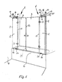
- a partition wall for shower has at least one fixed wall part 2 and a door 3, the wall part 2 being anchored, according to FIGS. 1 and 8 to 16 preferably anchored to a building wall 4 and adjustable in its use position in the area near the wall.
- the fixed wall part 2 is also supported on the edge of a shower tray 5 or a bathtub 6 and can support the door 3 via hinges 7. It would also be conceivable that the fixed wall part 2 could carry a sliding door over rails.
- the adjustment close to the wall can be carried out according to FIG. 1 with the aid of a U-profile 8, which is fastened on the one hand to the building wall 4 and accommodates the vertical edge 9 of the fixed wall part 2 close to the wall between its legs in an adaptable and somewhat displaceable manner.
- This solution with a U-profile 8 is also shown in FIGS. 8, 11, 12 u. 15 provided.
- Fig. 9 u. 10 is indicated that the wall anchoring can also be done with the help of elbows 10. Nevertheless, there are often inaccuracies on the vertical edge 11 of the fixed wall part opposite the edge 9 near the wall, so that a door connected or hinged there is difficult to seal and its edge may not exactly match this edge 11.
- this edge 11 can now be adjusted very precisely to the requirements of the position of a door 3, be it that the door 3 is pivotally attached to this edge 11 via hinges, be it that this edge 11 together with the free edge 12 of such a door 3 in the closed position should form the smallest possible joint or seals located in this area should be brought into contact as precisely as possible over the entire length of the joint.
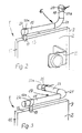
- the arm 15 of a pivoting lever 16 or a pushing lever 17 can engage on the upper edge 13 of the fixed wall part 2 of the partition 1, which free arm 15 in the horizontal direction transverse to the longitudinal extension of the upper, about horizontal edge 13 and also transversely to its own longitudinal extent is adjustable and fixable and via a fastening element, in the exemplary embodiment via a fork 18 spanning the upper edge 13 of the fixed wall part 2, but possibly also only with the aid of a flange or the like, on its adjusting movement transmits the fixed wall part 2.
- the free arm 15 and preferably the entire pivot lever 16 or push lever 17 is arranged above the upper edge 13 of the wall part 2. The adjustment movement can thus be carried out comfortably and also with the force required.
- a holding part 19 of the angular pivoting lever 16 arranged vertically in this case can be rotated and fixed, for example in one Clamp 20 is mounted on the building wall 4 and passes over an angle or a bend 21 into the free swivel arm 15 running parallel to the upper free edge 13 of the wall part 2.
- This arm 15 carries or penetrates in the region of its free end near the vertical boundary edge 11 of the wall part 2 opposite the fastening edge 9 on the wall, a sleeve 22 or the like coupling or connecting element which by means of the fork 18 or the like holding part, the fixed wall part 2 is positively gripped or overlapped.
- Both the clamp 20 and the sleeve 22 allow an alignment and adjustment of the entire pivot lever 16 to the local conditions and any inaccuracies in the building wall 4 on the one hand and the building-side adjustment of the fixed wall part 2 on the other.
- the edge 9 has to be displaced somewhat within the U-profile 8 or with respect to an angle piece 10
- the same displacement can be carried out with the sleeve 22 with respect to the arm 15 before the fixation takes place, for example, with the aid of a clamping screw 22a.
- the adjusting arm 15 of the swivel lever 16 or the push lever 17 to be described can pass through the sleeve 2 according to FIGS. 1 and 3 or end according to FIG. 2 in a sleeve 22 which is closed with respect to the entry of this arm 15 and in each case in this sleeve by means of the Clamping screw 22a can be fixed.
- edge 11 of the fixed wall part 2 is now to be adjusted transversely to the plane of this wall part 2, only the swivel arm 16 with its holding part 19 needs to be swiveled in the then released clamp 20, whereby the swivel arm 15 and the fork 18 carry out a corresponding horizontal swivel movement , by which the edge region 11 is adjusted accordingly in the upper part and at the upper edge 13 of the fixed wall part 2.
- FIG. 3 shows a modified, but functionally similar solution, which can be preferred, for example, if there is not much space above the fixed wall part 2.
- a somewhat horizontal leg 23 of the angular thrust lever 17 can be seen, which in the horizontal direction - in this case again on the building wall 4 - displaceable and fixable in its longitudinal direction of extension is also mounted in a clamp 20 and via an elbow or T-piece or a bend or a bend 21 in the approximately horizontal, again above the upper free edge 13 of the fixed wall part 2 extending arm 15 which, as in the exemplary embodiments described above, is held near the free vertical edge region 11 of the fixed wall part 2 by a sleeve 22 or similar coupling and with comparable connecting means, in this case again a fork 18, in a form-fitting manner with the fixed wall part 2 connected is.
- the lower edge 14 of the fixed wall part 2 can be adjusted and adjusted in an analogous manner, for which purpose it is gripped or acted upon by an approximately fork-shaped adjusting element 24 in the exemplary embodiments according to FIGS. 2 and 4 to 7 4, which can be seen particularly well in FIG. 4 and whose projections 25 are transverse to that formed by the fixed wall part 2 Level are adjustable while taking the detected edge area of the wall part 2.
- This adjusting element 24 has a lower plate 26, which can be fixed, for example, on a tub edge and relative to which the projections 25 can be adjusted, so that the lower edge 14 near the free edge 11 of the wall part 2 can be adjusted in the transverse direction.
- projections 25 are provided for the region of the wall part 2 to be adjusted, which extends over both sides and which can be rotated in the same direction about parallel vertical eccentric axes 27 and because of their corresponding eccentricity and thus their rotation in the same direction constant distance transversely to the fixed wall part 2 this can be adjusted accordingly and can be adjusted in a driving manner.
- FIG 5 shows, for example, a top view of this adjusting element 24 with two eccentrics 25, which are in a middle position, in which the lower edge 14 of the fixed wall part 2 extends over the center of the plate 26.
- FIG. 6 shows the greatest possible deflection of the edge 14 relative to the adjusting element 24 to the left and in FIG. 7 an opposite largest possible adjustment to the right, in which the two eccentrics 25 are rotated by 90 ° from their central position in FIG. 5 and are pivoted.
- About the size of the eccentricity of these projections 25 can thus be predetermined how large the possible swivel and adjustment path for the lower edge 14 of the fixed wall part should be at the fastening point of the adjusting element 24.
- FIG. 1 shows that it can be advantageous if a pivot lever 16 or a push lever 17 and an adjustment element 24 with eccentric projections 25 act on the upper edge 13 and on the lower edge 14 of the fixed wall part 2, because usually on the lower edge 14 is very little space, but a plate 26 with protruding eccentric projections 25 still fits between the edge of a tub and the lower edge 14, while on the upper edge 13 such an adjusting element 24 would only make sense if this upper edge 13 was practical would hit a building ceiling or the like upper limit, while at the otherwise usual large distances above the upper edge 13 of the pivot lever 16 or the push lever 17 are cheaper.
- the point of attack of the connecting element that is to say the fork 18, of the upper adjusting element, that is to say in the exemplary embodiment of the pivoting lever 16 or of the pushing lever 17, and that of the lower adjusting element 24 can lie opposite one another in the vertical direction, so that corresponding regions of the edges 13 and 14 are adjustable. as indicated in Fig.1. Depending on the gear ratios, however, it can also make sense to provide these attachment points offset in the horizontal direction.
- the adjusting elements engage directly on the wall part 2 formed, for example, by a glass plate and can be screwed to it. It is also avoided that any frames would have to be pivoted or bent when an adjustment with a deformation of the wall element 2 is required.
- each two fixed wall parts 2 arranged approximately at right angles to each other limit a shower cubicle located in a corner of the room and the distance between their free edges by a curved (FIG. 9), obliquely arranged (FIG. 10) or two swiveling or sliding doors 3 can also be closed and in FIG. 12 an entire side wall of a shower cubicle is formed by a fixed wall part 2, an embodiment can be seen in FIG. 8 in which two fixed wall parts 2 are arranged in a common plane, stand on a bathtub 6 and on each of these wall parts 2 a door 3 is pivotally or slidably mounted. In the closed position, these two doors 3 should be flush with their edges 12 facing away from the fixed wall parts 2.
- the doors 3 fastened to the fixed wall parts 2 via hinges 7 or the like have an overall center of gravity lying outside the plane of the fixed wall parts 2 due to a bend 28 or possibly an obtuse angle of their lower edge area, so that corresponding deflection forces from these Doors 3 extend over the hinges 7 to the fixed wall parts 2 and are transferred. These deflection forces can also be counteracted with the adjusting means according to the invention.
- the partition 1 for shower with at least one fixed wall part 2 and a door 3, which is anchored and in its position of use is particularly adjustable and adjustably attached to a building wall 4, also allows an adjustment of the wall distant edge 11 of the fixed wall part 2 in that on its upper edge 13 and / or lower edge 14 at a distance from the wall anchorage adjustment elements, for example arms 15 or Eccentric 25, for bending and pivoting the free edge 11 facing away from the anchoring point in an approximately horizontal direction and out of the original plane of the fixed wall part 2.
- two angularly meeting arms 15 are connected via a sliding sleeve 29 designed as a manifold, so that each arm 15 independently of the other in the horizontal direction according to the double arrows Pf 1 for performing the adjustment movements can be pivoted, whereby the relative movements occurring at the ends of the arms 15 within the sliding sleeve 29 can be compensated.
- a corner piece slidably engaging in the end faces of the arms 15 could also be provided.
- Fig. 14 shows that the one wall piece is held by a pivot lever 16 and the other wall piece by a push lever 17 to indicate that this connection of two extended arms 15 is possible with both types of levers.
- FIG. 15 and 16 show an exemplary embodiment similar to that of FIG. 1 or 2, with an approximately angular pivot lever 16, in turn, being mounted approximately in the plane of the fixed wall part 2 in a clamp 20 on the building wall 4, the latter of which vertical holding part 19 but via an angle or elbow 21 - not upwards as in FIG. 1, but - directed downwards and engages in a corresponding cutout 30 of the fixed wall part near the building wall 4.
- the anchoring of the fixed wall part 2 only extends to the lower limit of this cutout 30.
- this arrangement requires the arrangement of a cutout 30 on the fixed wall part 2, it can also be arranged in rooms with a lower ceiling or allows the fixed wall part 2 to approach the building ceiling without a push lever 17 with corresponding additional space for need to anchor it.
Landscapes
- Health & Medical Sciences (AREA)
- Public Health (AREA)
- Epidemiology (AREA)
- General Health & Medical Sciences (AREA)
- Hinges (AREA)
- Residential Or Office Buildings (AREA)
- Bathtubs, Showers, And Their Attachments (AREA)
- Nozzles (AREA)
Priority Applications (1)
| Application Number | Priority Date | Filing Date | Title |
|---|---|---|---|
| AT90124815T ATE101017T1 (de) | 1990-03-26 | 1990-12-19 | Trennwand fuer dusche mit justierbarem wandteil. |
Applications Claiming Priority (2)
| Application Number | Priority Date | Filing Date | Title |
|---|---|---|---|
| DE4009588 | 1990-03-26 | ||
| DE4009588A DE4009588A1 (de) | 1990-03-26 | 1990-03-26 | Trennwand fuer dusche mit justierbarem wandteil |
Publications (2)
| Publication Number | Publication Date |
|---|---|
| EP0448820A1 true EP0448820A1 (fr) | 1991-10-02 |
| EP0448820B1 EP0448820B1 (fr) | 1994-02-02 |
Family
ID=6403036
Family Applications (1)
| Application Number | Title | Priority Date | Filing Date |
|---|---|---|---|
| EP90124815A Expired - Lifetime EP0448820B1 (fr) | 1990-03-26 | 1990-12-19 | Paroi de séparation pour douche avec panneau ajustable |
Country Status (3)
| Country | Link |
|---|---|
| EP (1) | EP0448820B1 (fr) |
| AT (1) | ATE101017T1 (fr) |
| DE (2) | DE4009588A1 (fr) |
Cited By (6)
| Publication number | Priority date | Publication date | Assignee | Title |
|---|---|---|---|---|
| EP0581140A1 (fr) * | 1992-07-22 | 1994-02-02 | Beyerle, Andreas | Elément de serrage pour panneaux, notamment en verre |
| EP0619090A1 (fr) * | 1993-03-20 | 1994-10-12 | Hüppe GmbH & Co. | Dispositif pour maintenir une paroi de séparation fixe verticale, en particulier dans une cloison de douche |
| EP0619091A3 (fr) * | 1993-04-07 | 1995-04-26 | Munch Paul Jean | Poteau de fixation pour fixer et/ou renforcer des parois pour cabines de douche. |
| EP0710463A1 (fr) * | 1994-10-25 | 1996-05-08 | Paul-Jean Munch | Cloison pour douche |
| KR20030067277A (ko) * | 2002-02-07 | 2003-08-14 | 류황명 | 체결구 및 그 체결구를 사용하는 샤워 부스용 고정바 |
| GB2444398A (en) * | 2006-11-28 | 2008-06-04 | Brik Group Ltd | Modular Shower Enclosure |
Families Citing this family (5)
| Publication number | Priority date | Publication date | Assignee | Title |
|---|---|---|---|---|
| DE9418086U1 (de) * | 1994-11-11 | 1994-12-22 | Altura Leiden Holding B.V., Maastricht | Duschabtrennung |
| DE19501867A1 (de) * | 1995-01-23 | 1996-07-25 | Dettmann Detmar | Duschabtrennung mit vier geraden Flächen |
| DE19539614C1 (de) * | 1995-10-25 | 1997-02-13 | Kermi Gmbh | System zur Stabilisierung von Trennwänden |
| DE102004004217B4 (de) * | 2004-01-27 | 2005-10-20 | Dorma Gmbh & Co Kg | Sanitäreinrichtung |
| DE202020107464U1 (de) | 2020-12-22 | 2022-03-28 | Pauli + Sohn Gmbh Metallwaren | Haltevorrichtung zum Befestigen eines flächenförmigen Abtrennungselements und Abtrennungsanordnung mit einer Haltevorrichtung |
Citations (9)
| Publication number | Priority date | Publication date | Assignee | Title |
|---|---|---|---|---|
| US1693088A (en) * | 1926-01-18 | 1928-11-27 | Louis H Lehman | Shower inclosure |
| FR2413898A1 (fr) * | 1978-01-09 | 1979-08-03 | Granger Maurice | Dispositif porte-rideau escamotable |
| DE2952574A1 (de) * | 1979-12-28 | 1981-09-10 | ACO Gießerei und Kunststoffverarbeitung GmbH & Co, 5470 Andernach | Duschabtrennung fuer bade- oder duschwannen |
| EP0114903B1 (fr) * | 1983-01-26 | 1986-06-18 | Paul-Jean Munch | Ecran pour douche avec au moins une paroi fixe et au moins une porte coulissante |
| US4720876A (en) * | 1986-08-11 | 1988-01-26 | Fasco Products Division Of Indal Limited | Shower door system |
| DE8806702U1 (de) * | 1988-05-21 | 1988-07-07 | Hüppe GmbH & Co, 2903 Bad Zwischenahn | Duschabtrennung mit mindestens zwei über Eck angeordneten Trennelementen |
| DE8809618U1 (de) * | 1988-07-28 | 1988-12-22 | Greferath, Hans-Gerd, 4902 Bad Salzuflen | Duschabtrennung |
| EP0187190B1 (fr) * | 1984-12-14 | 1989-10-11 | Paul-Jean Munch | Cloison de séparation pour douche |
| EP0270739B1 (fr) * | 1986-11-22 | 1991-07-17 | Paul-Jean Munch | Cloison pour douche |
Family Cites Families (1)
| Publication number | Priority date | Publication date | Assignee | Title |
|---|---|---|---|---|
| DE3104222A1 (de) * | 1981-02-06 | 1982-08-19 | Paul-Jean 7816 Münstertal Munch | "duschkabine" |
-
1990
- 1990-03-26 DE DE4009588A patent/DE4009588A1/de active Granted
- 1990-12-19 AT AT90124815T patent/ATE101017T1/de not_active IP Right Cessation
- 1990-12-19 DE DE90124815T patent/DE59004521D1/de not_active Expired - Fee Related
- 1990-12-19 EP EP90124815A patent/EP0448820B1/fr not_active Expired - Lifetime
Patent Citations (9)
| Publication number | Priority date | Publication date | Assignee | Title |
|---|---|---|---|---|
| US1693088A (en) * | 1926-01-18 | 1928-11-27 | Louis H Lehman | Shower inclosure |
| FR2413898A1 (fr) * | 1978-01-09 | 1979-08-03 | Granger Maurice | Dispositif porte-rideau escamotable |
| DE2952574A1 (de) * | 1979-12-28 | 1981-09-10 | ACO Gießerei und Kunststoffverarbeitung GmbH & Co, 5470 Andernach | Duschabtrennung fuer bade- oder duschwannen |
| EP0114903B1 (fr) * | 1983-01-26 | 1986-06-18 | Paul-Jean Munch | Ecran pour douche avec au moins une paroi fixe et au moins une porte coulissante |
| EP0187190B1 (fr) * | 1984-12-14 | 1989-10-11 | Paul-Jean Munch | Cloison de séparation pour douche |
| US4720876A (en) * | 1986-08-11 | 1988-01-26 | Fasco Products Division Of Indal Limited | Shower door system |
| EP0270739B1 (fr) * | 1986-11-22 | 1991-07-17 | Paul-Jean Munch | Cloison pour douche |
| DE8806702U1 (de) * | 1988-05-21 | 1988-07-07 | Hüppe GmbH & Co, 2903 Bad Zwischenahn | Duschabtrennung mit mindestens zwei über Eck angeordneten Trennelementen |
| DE8809618U1 (de) * | 1988-07-28 | 1988-12-22 | Greferath, Hans-Gerd, 4902 Bad Salzuflen | Duschabtrennung |
Cited By (6)
| Publication number | Priority date | Publication date | Assignee | Title |
|---|---|---|---|---|
| EP0581140A1 (fr) * | 1992-07-22 | 1994-02-02 | Beyerle, Andreas | Elément de serrage pour panneaux, notamment en verre |
| EP0619090A1 (fr) * | 1993-03-20 | 1994-10-12 | Hüppe GmbH & Co. | Dispositif pour maintenir une paroi de séparation fixe verticale, en particulier dans une cloison de douche |
| EP0619091A3 (fr) * | 1993-04-07 | 1995-04-26 | Munch Paul Jean | Poteau de fixation pour fixer et/ou renforcer des parois pour cabines de douche. |
| EP0710463A1 (fr) * | 1994-10-25 | 1996-05-08 | Paul-Jean Munch | Cloison pour douche |
| KR20030067277A (ko) * | 2002-02-07 | 2003-08-14 | 류황명 | 체결구 및 그 체결구를 사용하는 샤워 부스용 고정바 |
| GB2444398A (en) * | 2006-11-28 | 2008-06-04 | Brik Group Ltd | Modular Shower Enclosure |
Also Published As
| Publication number | Publication date |
|---|---|
| EP0448820B1 (fr) | 1994-02-02 |
| DE59004521D1 (de) | 1994-03-17 |
| DE4009588C2 (fr) | 1992-04-16 |
| ATE101017T1 (de) | 1994-02-15 |
| DE4009588A1 (de) | 1991-10-02 |
Similar Documents
| Publication | Publication Date | Title |
|---|---|---|
| DE3445642C2 (fr) | ||
| EP0297202B1 (fr) | Bras de compas pour fenêtre coulissante se déplaçant dans un plan parallèle | |
| DE69832772T2 (de) | Schiebefenster- und Türanordnung | |
| EP0065109B1 (fr) | Charnière | |
| EP0448820B1 (fr) | Paroi de séparation pour douche avec panneau ajustable | |
| DE3738596C2 (fr) | ||
| EP0118883B1 (fr) | Séparation de douche en forme de trappe | |
| DE4101363C1 (fr) | ||
| EP0174583B1 (fr) | Cloison de séparation pour douche | |
| EP0784956A1 (fr) | Cloison de douche | |
| EP0270739B1 (fr) | Cloison pour douche | |
| EP0087822B1 (fr) | Porte pliante | |
| DE69102680T2 (de) | Scharnier geeignet zur Anwendung in einer Dachlukenmontage. | |
| EP1013210B1 (fr) | Cloison de douche | |
| CH714546A2 (de) | Vorrichtung zum Öffnen einer Gebäudedachöffnung. | |
| CH657659A5 (de) | Drehkippfenster oder drehkipptuer mit einem seitenscharnier und einem ausstellarm. | |
| DE29602765U1 (de) | An unterschiedliche Breitenabmessungen anpaßbare Duschabtrennung | |
| DE29514829U1 (de) | Beschlag für einen zumindest annähernd parallel abstellbaren und in dieser Parallellage horizontal verschiebbaren Flügel von Fenstern, Türen o.dgl. | |
| EP0675253A1 (fr) | Porte sectionnelle | |
| DE19839380A1 (de) | Duschabtrennung | |
| EP1681400B1 (fr) | Fenêtre de toiture avec volet roulant | |
| DE1584083A1 (de) | Sicherungsvorrichtung fuer Schwenk-Kippfluegel von Fenstern,Tueren od. dgl. | |
| EP1589164B1 (fr) | Cabine montable contre un mur de bâtiment | |
| EP0989273A1 (fr) | Charnière avec centre de rotation mobile | |
| DE2552168C2 (de) | Vorrichtung mit einem Koppelbeschlag zum Verbinden von einem äußeren Fensterflügel mit einem im Abstand dazu angeordneten inneren Fensterflügel |
Legal Events
| Date | Code | Title | Description |
|---|---|---|---|
| PUAI | Public reference made under article 153(3) epc to a published international application that has entered the european phase |
Free format text: ORIGINAL CODE: 0009012 |
|
| AK | Designated contracting states |
Kind code of ref document: A1 Designated state(s): AT BE CH DE ES FR GB IT LI NL SE |
|
| 17P | Request for examination filed |
Effective date: 19910920 |
|
| 17Q | First examination report despatched |
Effective date: 19921124 |
|
| GRAA | (expected) grant |
Free format text: ORIGINAL CODE: 0009210 |
|
| AK | Designated contracting states |
Kind code of ref document: B1 Designated state(s): AT BE CH DE ES FR GB IT LI NL SE |
|
| PG25 | Lapsed in a contracting state [announced via postgrant information from national office to epo] |
Ref country code: IT Free format text: LAPSE BECAUSE OF FAILURE TO SUBMIT A TRANSLATION OF THE DESCRIPTION OR TO PAY THE FEE WITHIN THE PRE;WARNING: LAPSES OF ITALIAN PATENTS WITH EFFECTIVE DATE BEFORE 2007 MAY HAVE OCCURRED AT ANY TIME BEFORE 2007. THE CORRECT EFFECTIVE DATE MAY BE DIFFERENT FROM THE ONE RECORDED.SCRIBED TIME-LIMIT Effective date: 19940202 Ref country code: ES Free format text: THE PATENT HAS BEEN ANNULLED BY A DECISION OF A NATIONAL AUTHORITY Effective date: 19940202 Ref country code: SE Effective date: 19940202 |
|
| REF | Corresponds to: |
Ref document number: 101017 Country of ref document: AT Date of ref document: 19940215 Kind code of ref document: T |
|
| REF | Corresponds to: |
Ref document number: 59004521 Country of ref document: DE Date of ref document: 19940317 |
|
| ET | Fr: translation filed | ||
| GBT | Gb: translation of ep patent filed (gb section 77(6)(a)/1977) |
Effective date: 19940511 |
|
| PLBE | No opposition filed within time limit |
Free format text: ORIGINAL CODE: 0009261 |
|
| STAA | Information on the status of an ep patent application or granted ep patent |
Free format text: STATUS: NO OPPOSITION FILED WITHIN TIME LIMIT |
|
| 26N | No opposition filed | ||
| REG | Reference to a national code |
Ref country code: GB Ref legal event code: IF02 |
|
| PGFP | Annual fee paid to national office [announced via postgrant information from national office to epo] |
Ref country code: AT Payment date: 20031106 Year of fee payment: 14 |
|
| PGFP | Annual fee paid to national office [announced via postgrant information from national office to epo] |
Ref country code: FR Payment date: 20031110 Year of fee payment: 14 |
|
| PGFP | Annual fee paid to national office [announced via postgrant information from national office to epo] |
Ref country code: NL Payment date: 20031117 Year of fee payment: 14 Ref country code: CH Payment date: 20031117 Year of fee payment: 14 |
|
| PGFP | Annual fee paid to national office [announced via postgrant information from national office to epo] |
Ref country code: GB Payment date: 20031118 Year of fee payment: 14 |
|
| PGFP | Annual fee paid to national office [announced via postgrant information from national office to epo] |
Ref country code: DE Payment date: 20031125 Year of fee payment: 14 |
|
| PGFP | Annual fee paid to national office [announced via postgrant information from national office to epo] |
Ref country code: BE Payment date: 20031217 Year of fee payment: 14 |
|
| PG25 | Lapsed in a contracting state [announced via postgrant information from national office to epo] |
Ref country code: AT Free format text: LAPSE BECAUSE OF NON-PAYMENT OF DUE FEES Effective date: 20041219 Ref country code: GB Free format text: LAPSE BECAUSE OF NON-PAYMENT OF DUE FEES Effective date: 20041219 |
|
| PG25 | Lapsed in a contracting state [announced via postgrant information from national office to epo] |
Ref country code: CH Free format text: LAPSE BECAUSE OF NON-PAYMENT OF DUE FEES Effective date: 20041231 Ref country code: BE Free format text: LAPSE BECAUSE OF NON-PAYMENT OF DUE FEES Effective date: 20041231 Ref country code: LI Free format text: LAPSE BECAUSE OF NON-PAYMENT OF DUE FEES Effective date: 20041231 |
|
| BERE | Be: lapsed |
Owner name: *MUNCH PAUL-JEAN Effective date: 20041231 |
|
| PG25 | Lapsed in a contracting state [announced via postgrant information from national office to epo] |
Ref country code: NL Free format text: LAPSE BECAUSE OF NON-PAYMENT OF DUE FEES Effective date: 20050701 Ref country code: DE Free format text: LAPSE BECAUSE OF NON-PAYMENT OF DUE FEES Effective date: 20050701 |
|
| GBPC | Gb: european patent ceased through non-payment of renewal fee |
Effective date: 20041219 |
|
| REG | Reference to a national code |
Ref country code: CH Ref legal event code: PL |
|
| PG25 | Lapsed in a contracting state [announced via postgrant information from national office to epo] |
Ref country code: FR Free format text: LAPSE BECAUSE OF NON-PAYMENT OF DUE FEES Effective date: 20050831 |
|
| NLV4 | Nl: lapsed or anulled due to non-payment of the annual fee |
Effective date: 20050701 |
|
| REG | Reference to a national code |
Ref country code: FR Ref legal event code: ST |
|
| BERE | Be: lapsed |
Owner name: *MUNCH PAUL-JEAN Effective date: 20041231 |