EP0449147A2 - Adaptive federnde Radaufhängung für Kraftfahrzeuge - Google Patents
Adaptive federnde Radaufhängung für Kraftfahrzeuge Download PDFInfo
- Publication number
- EP0449147A2 EP0449147A2 EP91104577A EP91104577A EP0449147A2 EP 0449147 A2 EP0449147 A2 EP 0449147A2 EP 91104577 A EP91104577 A EP 91104577A EP 91104577 A EP91104577 A EP 91104577A EP 0449147 A2 EP0449147 A2 EP 0449147A2
- Authority
- EP
- European Patent Office
- Prior art keywords
- incident
- suspension system
- cylinder unit
- supply
- automotive vehicle
- Prior art date
- Legal status (The legal status is an assumption and is not a legal conclusion. Google has not performed a legal analysis and makes no representation as to the accuracy of the status listed.)
- Granted
Links
- 239000000725 suspension Substances 0.000 title claims abstract description 51
- 239000012530 fluid Substances 0.000 claims abstract description 47
- 230000001133 acceleration Effects 0.000 claims abstract description 35
- 238000007599 discharging Methods 0.000 claims abstract description 20
- 238000012937 correction Methods 0.000 claims description 21
- 230000001276 controlling effect Effects 0.000 claims description 16
- 230000004044 response Effects 0.000 claims description 11
- 230000001105 regulatory effect Effects 0.000 claims description 3
- 230000008901 benefit Effects 0.000 abstract description 6
- 239000007788 liquid Substances 0.000 description 94
- 230000005856 abnormality Effects 0.000 description 15
- 238000012545 processing Methods 0.000 description 10
- 238000004891 communication Methods 0.000 description 9
- 238000010586 diagram Methods 0.000 description 6
- 238000010276 construction Methods 0.000 description 5
- 230000005284 excitation Effects 0.000 description 4
- 238000012544 monitoring process Methods 0.000 description 4
- 230000002093 peripheral effect Effects 0.000 description 4
- 230000002159 abnormal effect Effects 0.000 description 3
- 230000009471 action Effects 0.000 description 3
- 238000011144 upstream manufacturing Methods 0.000 description 3
- 230000003111 delayed effect Effects 0.000 description 2
- 230000008859 change Effects 0.000 description 1
- 238000013016 damping Methods 0.000 description 1
- 230000005611 electricity Effects 0.000 description 1
- 230000002708 enhancing effect Effects 0.000 description 1
- 230000005484 gravity Effects 0.000 description 1
- 238000012986 modification Methods 0.000 description 1
- 230000004048 modification Effects 0.000 description 1
- 230000002265 prevention Effects 0.000 description 1
- 230000000717 retained effect Effects 0.000 description 1
- 238000005096 rolling process Methods 0.000 description 1
Images




Classifications
-
- B—PERFORMING OPERATIONS; TRANSPORTING
- B60—VEHICLES IN GENERAL
- B60G—VEHICLE SUSPENSION ARRANGEMENTS
- B60G17/00—Resilient suspensions having means for adjusting the spring or vibration-damper characteristics, for regulating the distance between a supporting surface and a sprung part of vehicle or for locking suspension during use to meet varying vehicular or surface conditions, e.g. due to speed or load
- B60G17/015—Resilient suspensions having means for adjusting the spring or vibration-damper characteristics, for regulating the distance between a supporting surface and a sprung part of vehicle or for locking suspension during use to meet varying vehicular or surface conditions, e.g. due to speed or load the regulating means comprising electric or electronic elements
- B60G17/016—Resilient suspensions having means for adjusting the spring or vibration-damper characteristics, for regulating the distance between a supporting surface and a sprung part of vehicle or for locking suspension during use to meet varying vehicular or surface conditions, e.g. due to speed or load the regulating means comprising electric or electronic elements characterised by their responsiveness, when the vehicle is travelling, to specific motion, a specific condition, or driver input
- B60G17/0162—Resilient suspensions having means for adjusting the spring or vibration-damper characteristics, for regulating the distance between a supporting surface and a sprung part of vehicle or for locking suspension during use to meet varying vehicular or surface conditions, e.g. due to speed or load the regulating means comprising electric or electronic elements characterised by their responsiveness, when the vehicle is travelling, to specific motion, a specific condition, or driver input mainly during a motion involving steering operation, e.g. cornering, overtaking
-
- B—PERFORMING OPERATIONS; TRANSPORTING
- B60—VEHICLES IN GENERAL
- B60G—VEHICLE SUSPENSION ARRANGEMENTS
- B60G2202/00—Indexing codes relating to the type of spring, damper or actuator
- B60G2202/10—Type of spring
- B60G2202/15—Fluid spring
- B60G2202/154—Fluid spring with an accumulator
-
- B—PERFORMING OPERATIONS; TRANSPORTING
- B60—VEHICLES IN GENERAL
- B60G—VEHICLE SUSPENSION ARRANGEMENTS
- B60G2204/00—Indexing codes related to suspensions per se or to auxiliary parts
- B60G2204/80—Interactive suspensions; arrangement affecting more than one suspension unit
- B60G2204/82—Interactive suspensions; arrangement affecting more than one suspension unit left and right unit on same axle
-
- B—PERFORMING OPERATIONS; TRANSPORTING
- B60—VEHICLES IN GENERAL
- B60G—VEHICLE SUSPENSION ARRANGEMENTS
- B60G2400/00—Indexing codes relating to detected, measured or calculated conditions or factors
- B60G2400/10—Acceleration; Deceleration
- B60G2400/102—Acceleration; Deceleration vertical
-
- B—PERFORMING OPERATIONS; TRANSPORTING
- B60—VEHICLES IN GENERAL
- B60G—VEHICLE SUSPENSION ARRANGEMENTS
- B60G2400/00—Indexing codes relating to detected, measured or calculated conditions or factors
- B60G2400/10—Acceleration; Deceleration
- B60G2400/104—Acceleration; Deceleration lateral or transversal with regard to vehicle
-
- B—PERFORMING OPERATIONS; TRANSPORTING
- B60—VEHICLES IN GENERAL
- B60G—VEHICLE SUSPENSION ARRANGEMENTS
- B60G2400/00—Indexing codes relating to detected, measured or calculated conditions or factors
- B60G2400/20—Speed
- B60G2400/204—Vehicle speed
-
- B—PERFORMING OPERATIONS; TRANSPORTING
- B60—VEHICLES IN GENERAL
- B60G—VEHICLE SUSPENSION ARRANGEMENTS
- B60G2400/00—Indexing codes relating to detected, measured or calculated conditions or factors
- B60G2400/25—Stroke; Height; Displacement
- B60G2400/252—Stroke; Height; Displacement vertical
-
- B—PERFORMING OPERATIONS; TRANSPORTING
- B60—VEHICLES IN GENERAL
- B60G—VEHICLE SUSPENSION ARRANGEMENTS
- B60G2400/00—Indexing codes relating to detected, measured or calculated conditions or factors
- B60G2400/30—Propulsion unit conditions
-
- B—PERFORMING OPERATIONS; TRANSPORTING
- B60—VEHICLES IN GENERAL
- B60G—VEHICLE SUSPENSION ARRANGEMENTS
- B60G2400/00—Indexing codes relating to detected, measured or calculated conditions or factors
- B60G2400/40—Steering conditions
- B60G2400/41—Steering angle
-
- B—PERFORMING OPERATIONS; TRANSPORTING
- B60—VEHICLES IN GENERAL
- B60G—VEHICLE SUSPENSION ARRANGEMENTS
- B60G2400/00—Indexing codes relating to detected, measured or calculated conditions or factors
- B60G2400/50—Pressure
- B60G2400/51—Pressure in suspension unit
-
- B—PERFORMING OPERATIONS; TRANSPORTING
- B60—VEHICLES IN GENERAL
- B60G—VEHICLE SUSPENSION ARRANGEMENTS
- B60G2400/00—Indexing codes relating to detected, measured or calculated conditions or factors
- B60G2400/50—Pressure
- B60G2400/51—Pressure in suspension unit
- B60G2400/518—Pressure in suspension unit in damper
-
- B—PERFORMING OPERATIONS; TRANSPORTING
- B60—VEHICLES IN GENERAL
- B60G—VEHICLE SUSPENSION ARRANGEMENTS
- B60G2600/00—Indexing codes relating to particular elements, systems or processes used on suspension systems or suspension control systems
- B60G2600/04—Means for informing, instructing or displaying
-
- B—PERFORMING OPERATIONS; TRANSPORTING
- B60—VEHICLES IN GENERAL
- B60G—VEHICLE SUSPENSION ARRANGEMENTS
- B60G2600/00—Indexing codes relating to particular elements, systems or processes used on suspension systems or suspension control systems
- B60G2600/22—Magnetic elements
- B60G2600/26—Electromagnets; Solenoids
-
- B—PERFORMING OPERATIONS; TRANSPORTING
- B60—VEHICLES IN GENERAL
- B60G—VEHICLE SUSPENSION ARRANGEMENTS
- B60G2800/00—Indexing codes relating to the type of movement or to the condition of the vehicle and to the end result to be achieved by the control action
- B60G2800/24—Steering, cornering
Definitions
- the present invention relates to a suspension system for an automotive vehicle so adapted as to control the posture of an automotive vehicle body by controlling the supply or discharge of a fluid to or from a cylinder and, more particularly, to a suspension system for the automotive vehicle involved particularly with fail safe measures in the event of an incident in a supply-discharge control system.
- a suspension system for the automotive vehicle is known, for example, as disclosed in Japanese Patent Laid-open Publication (kokai) No. 130,418/1988, which has plural cylinders disposed between a sprang weight and an unsprung weight for each wheel, to each of which plural gas springs are connected so as to allow the independent and separate supply or discharge of the fluid to each cylinder, thereby performing the control over the posture of the automotive vehicle body.
- This system is known as an active control suspension system (ACS system).
- a supply-discharge control valve for supplying or discharging an operating fluid is so arranged as to be controlled by supply or discharge control means under a predetermined condition.
- an incident may be caused to occur to such an extent that the supply-discharge control means cannot work in a correct way.
- Such an incident is considered to include incidents with respect to the supply-discharge control means itself as well as various sensors, fluid circuits for supplying or discharging the fluid, among many others. When those incidents occur, the posture of the automotive vehicle body cannot be controlled in a normal way so that the control by the supply-discharge control means should be suspended.
- the automotive vehicle body is kept leaning (rolling) even if the automotive vehicle body is returned to the straight running state.
- transverse acceleration acts upon the automotive vehicle body as centrifugal force, thereby causing the automotive vehicle body to lean in the direction in which the transverse acceleration works and imposing different loads onto the left-hand and right-hand wheels.
- the ACS system is so designed as to control the different loads disposed upon the left-hand and right-hand wheels by changing inner pressures within the respective cylinders for the left-hand and right-hand wheels.
- the object of the present invention is to provide a suspension system for an automotive vehicle so adapted as to appropriately cope with abnormal implementation of control over the posture of the automotive vehicle body by supplying or discharging the operating fluid to or from the cylinder units, even if an incident would occur during cornering of the automotive vehicle body.
- the present invention is basically so constructed as to suspend the control over the posture of the automotive vehicle body upon occurrence of an incident and, further, to provide a predetermined correcting condition in suspending the control during cornering.
- the present invention consists of a suspension system for an automotive vehicle, comprising: a cylinder unit interposed between a sprang weight and an unsprung weight for each wheel; supply-discharge means for supplying or discharging an operating fluid to or from the cylinder unit; supply-discharge control means for controlling the supply-discharge means under a predetermined condition; incident detecting means for detecting occurrence of an incident which impedes normal implementation of control by the supply-discharge control means; suspension means for suspending the control by the supply-discharge means when the incident is detected by the incident detecting means; and cornering detecting means for detecting cornering of an automotive vehicle body; and correction means for providing the suspension means with a predetermined correcting condition when the cornering of the automotive vehicle body is detected by the cornering detecting means.
- the correcting condition to be provided upon the suspension of the control over the posture of the automotive vehicle body may preferably include a condition for lowering a vehicle height of the automotive vehicle body by forcibly discharging the operating fluid from the cylinder units.
- the lowering of the vehicle height thereof serves as improving stability of the automotive vehicle body as well as suppressing the automotive vehicle body from leaning.
- the suspension system according to the present invention can prevent the situation from occurring, which involves leaning largely in the direction opposite to the direction in which the automotive vehicle body is leaned during cornering, when the automotive vehicle body is returned to its straight running state from its cornering state.
- a decision to determine if the automotive vehicle body is cornering can be made, for example, by taking advantage of a steered angle of a steering wheel, transverse acceleration, and so on. Further, the cornering of the automotive vehicle body can be determined by taking advantage of a difference in inner pressures between the left-hand and right-hand cylinder units.
- the vehicle height of the automotive vehicle body be lowered at the timing when the automotive vehicle body is returned to its nearly straight running state after the control over the posture of the automotive vehicle body has been suspended.
- the incident mode may include a first incident mode for suspending the control over the posture of the automotive vehicle body by lowering the vehicle height of the automotive vehicle body and a second incident mode for suspending the control over the posture of the automotive vehicle body while maintaining the current vehicle height of the automotive vehicle body. Even if the kind of the incident would correspond to the second incident mode, it can be modified so as to correspond to the first incident mode by the correction means during occurrence of an incident during cornering of the automotive vehicle body.
- the high pressure line through which the high pressure operating fluid passes is released to the low pressure line, i.e. a reservoir tank.
- This arrangement for the high pressure line can ensure prevention of the high pressure operating fluid from being supplied erroneously to the cylinder units for some reasons.
- Fig. 1 is a block diagram showing an entire layout of the suspension system for the automotive vehicle according to an embodiment of the present invention.
- Fig. 2 is a diagrammatic representation of a hydraulic pressure circuit for supplying or discharging the operating fluid in the suspension system for the automotive vehicle according to the embodiment of the present invention.
- Fig. 3 is a block diagram showing the construction of the controller 19 and its peripheral units or sections.
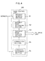
- Fig. 4 is a block diagram showing the construction of the main control unit 100.
- Fig. 5 is a diagrammatic representation of a system for supplying the power source to the controller 19 and its peripheral units or sections.
- Fig. 6 is a flowchart showing a fail safe control in the controller 19.
- Fig. 7 is a flowchart showing an example of decision to determine if the automotive vehicle body is cornering.
- Fig. 8 is a flowchart showing a variant according to the present invention.
- reference numeral 1 stands for an automotive vehicle body, reference numeral 2F for a front wheel, and reference numeral 2R for a rear wheel. Between the vehicle body 1 as sprang weight and each of the front wheel 2F and the rear wheel 2R as unsprung weight is interposed a liquid cylinder 3.
- Each of the liquid cylinders 3 is divided into or defined by a liquid pressure chamber 3c by a piston 3b inserted into a cylinder body 3a.
- An upper end portion of a connecting rod 3d connected to the piston 3b is connected to the automotive vehicle body 1 and the cylinder body 3a is connected to each of the front wheels 2F and the rear wheels 2R.
- the inside of the cylinder body 3a constitutes substantially one liquid pressure chamber 3c regardless of the disposition of the piston 3b.
- the liquid pressure chamber 3c comprises an upper liquid pressure chamber section located above the piston 3b and a lower liquid pressure chamber section located underneath the piston 3b, and both of the two liquid pressure chamber sections are always communicated with each other through a communication hole or a cut-off portion formed on the piston 3b.
- a gas spring 5 which in turn is divided into a gas chamber 5f and a liquid pressure chamber 5g by a diaphragm 5e and the liquid pressure chamber 5g is communicated with the liquid pressure chamber 3c of each of the liquid cylinders 3.
- reference numeral 8 denotes a hydraulic pressure pump 8 which is communicated with each of the liquid cylinders 3 through a liquid pressure passage 10 as a high pressure line
- reference numeral 9 denotes a flow rate control valve which is mounted to the liquid pressure passage 10 and which has the function of adjusting an inner pressure, i.e. the liquid pressure within the liquid pressure chamber 3c, by supplying or discharging the liquid, or oil, to or from each of liquid cylinders 3.
- reference numeral 12 stands for a main pressure sensor for sensing the pressure for discharging the liquid of the hydraulic pressure pump 8, i.e. the pressure of the liquid accumulated in each of accumulators 22a and 22b
- reference numeral 13 for a cylinder pressure sensor for sensing the liquid pressure of the liquid pressure chamber 3c of each of the liquid cylinders 3
- reference numeral 14 for a vehicle height sensor for sensing a vehicle height, i.e.
- reference numeral 15 for a vertical acceleration sensor for sensing vertical acceleration of the automotive vehicle, or sprang acceleration of the front and rear wheels 2F and 2R, as will be described hereinafter in more detail
- reference numeral 17 for an ignition switch for a parking switch.
- the signals sensed by these sensors and the shift signals outputted from these switches are inputted into a controller 19 composed of a microcomputer having a CPU, etc., and they are employed for controlling changes of suspension characteristics.
- Fig. 2 shows a hydraulic pressure circuit for controlling the supply or discharge of the liquid to or from the the liquid cylinders 3.
- the hydraulic pressure pump 8 comprises a swash plate type piston pump of a variable volume type and it is connected in two rows to a hydraulic pressure pump 21 for power steering unit drivable by a driving source 20.
- the liquid pressure passage 10 connected to the hydraulic pressure pump 8 are communicated three accumulators 22a, 22a and 22a at identical sites at which the liquid pressure passage 10 is in turn branched into a front wheel liquid pressure passage 10F and a rear wheel liquid pressure 10R.
- the front wheel liquid pressure passage 10F is further branched into a left-hand front wheel liquid pressure passage 10FL and a right-hand front wheel liquid pressure 10FR.
- the front wheel liquid pressure passage 10FL is communicated with the liquid pressure chamber 3c of a left-hand liquid cylinder 3FL of the respective wheel while the right-hand front wheel liquid pressure passage 10FR is communicated with the liquid pressure chamber 3c of a right-hand liquid cylinder 3FR of the respective wheel.
- the rear wheel liquid pressure passage 10R is communicated with one accumulator 22b and it is divided into a left-hand rear wheel liquid pressure 10RL and a right-hand rear wheel liquid pressure 10RR on the downstream side of the accumulator 22b.
- the left-hand rear wheel liquid pressure passage 10RL is communicated with the liquid pressure chamber 3c of the left-hand rear liquid cylinder 3RL of the respective wheel while the right-hand rear wheel liquid pressure passage 10RR is communicated with the liquid pressure chamber 3c of the right-hand rear liquid cylinder 3RR thereof.
- Each of the liquid cylinders 3FL, 3FR, 3RL and 3RR is connected to a plurality of gas springs 5FL, 5FR, 5RL and 5RR, respectively.
- the gas springs 5FL, 5FR, 5RR and 5RL in this embodiment, there are provided four of the gas springs,i.e. first gas spring 5a, second gas spring 5b, third gas spring 5c, and fourth gas spring 5d, for example, which are disposed in parallel to each other and communicated with the liquid pressure chamber 3c of the respective liquid cylinder 3 through the communication passage 4.
- Each of the gas springs 5a, 5b, 5c and 5d is provided with an orifice 25 at its branch portion of the communication passage 4, and the orifice 25 is so disposed as to exhibit both its damping action and buffer action in association with gas filled in the gas chamber 5f.
- the communication passage 4 is provided in a position between the first gas spring 5a and the second gas spring 5b with a damping-force shifting valve 26 for adjusting a passage area of the communication passage 4 and the damping-force shifting valve 26 is so arranged as to assume two positions, an open position in which the communication passage 4 is opened and a closed position in which the passage area of the communication passage 4 is restricted to a remarkable extent.
- an unload valve 27 on the upstream side of the accumulator 22a which functions as controlling the oil discharge pressure of the hydraulic pressure pump 8 so as to retain within a predetermined range, i.e. 120 to 160 kgf/cm2.
- the unload valve 27 is so arranged as to assume a supply position and a discharge position. More specifically, when the unload valve 27 assumes its supply position, on the one hand, the amount of the liquid to be discharged from the hydraulic pressure pump 8 by introducing the pressure liquid to be discharged from the hydraulic pressure pump 8 into a swash-plate operating cylinder 8a of the hydraulic pressure pump 8. When the unload valve 27 assumes its closed position, on the other hand, the pressure liquid within the cylinder 8a is discharged.
- the unload valve 27 is further so arranged as to shift its position from the discharge position to thesupply position when the pressure at which the liquid is discharged from the hydraulic pressure pump 8 exceeds a predetermined upper limit discharge liquid pressure, i.e. 160 ⁇ 10 kgf/cm2, and then as to maintain its state until the liquid pressure reaches a predetermined lower limit discharge liquid pressure, e.g. 120 ⁇ 10 kgf/cm2, or lower.
- a predetermined upper limit discharge liquid pressure i.e. 160 ⁇ 10 kgf/cm2
- a predetermined lower limit discharge liquid pressure e.g. 120 ⁇ 10 kgf/cm2, or lower.
- the unload valve 27 exhibits the function of controlling the discharge liquid pressure of the hydraulic pressure pump 8 within a predetermined range From 120 kgf/cm2 to 160 kgf/cm2.
- the flow rate control valve 28 is so arranged as to assume both of a supply position in which the pressure oil is introduced from the hydraulic pressure pump 8 to the swash-plate operating cylinder 8a through the unload valve 27, and a discharge position in which the pressure oil within the cylinder 8a is discharged from the unload valve 27 to a reserve tank 29.
- This flow rate control valve 28 functions as controlling the amount of the liquid discharged from the hydraulic pressure pump 8 to a constant level by constantly retaining the differential pressure between the upstream side and the downstream side at the portion where a restrictor 30 for the liquid pressure passage 10 is disposed, when the liquid discharge pressure of the hydraulic pressure pump 8 is retained within the predetermined range by the unload valve 27.
- the liquid is supplied as a main pressure to each of the liquid cylinders 3 by accumulating the liquid for the accumulators 22a and 22b.
- the flow rate control valve 9 comprises a supply control valve 35 disposed on the left-hand liquid pressure passage 10FL of the liquid pressure passage 10, and a discharge control valve 37 disposed on a low pressure line 36 for discharging the liquid or oil from the left-hand liquid pressure passage 10FL to the reserve tank 29.
- Each of the supply control valve 35 and the discharge control valve 37 is so arranged as to assume two positions, i.e. an open position and a closed position, and has a differential pressure valve built therein in order to retain the liquid pressure at its open position at a predetermined value.
- a check valve 38 of a type operative in response to pilot pressure, as means for retaining pressure On the left-hand front wheel liquid pressure passage 10FL extending between the supply control valve 35 and the left-hand front liquid cylinder 3FL, there is disposed a check valve 38 of a type operative in response to pilot pressure, as means for retaining pressure.
- the check valve 38 is so disposed as to be closed when the pilot pressure reaches 40 kgf/cm2 or lower by introducing the oil pressure, i.e. main pressure, as a pilot pressure, within the liquid pressure passage 10 on the upstream side of the supply control valve 35 of the flow rate control valve 9 through a pilot line 39.
- main pressure i.e. main pressure
- the pressure oil can be supplied to the liquid cylinder 3 as well as the liquid or oil within the liquid cylinder 3 can be discharged.
- reference numeral 41 denotes a fail safe valve so disposed on the communication passage 42 communicating the liquid pressure passage 10 on the downstream side of the accumulator 22a with, the low pressure line 36 as to function as releasing a high pressure state by returning the oil accumulated in the accumulators 22a and 22b to the reserve tank 29 by shifting to its open position at the time of an incident.
- Reference numeral 43 denotes a restrictor so disposed on the pilot line 39 as to have the function of delaying the closing of the check valve 38 at the time when the fail safe valve 41 is operated to open.
- reference numeral 44 denotes a relief valve capable of returning the liquid or oil to the low pressure line 36 by operating to open when the oil pressure of the liquid pressure chamber 3c of each of the left-hand front liquid cylinder 3FL and the right-hand front liquid cylinder 3FR is raised to an abnormally high level.
- Reference numeral 45 denotes a return accumulator so connected to the low pressure line 36 as to perform the action of accumulating the liquid or oil when the liquid or oil is discharged from the liquid chamber 3.
- the controller 19 may be comprised of a micro-computer and arranged to perform the following control over the supply or discharge of the fluid to or from each of the fluid cylinders 3, which basically includes: control over the vehicle height to assume a target vehicle height on the basis of a signal sensed by the vehicle height sensor for each of the wheels; control to reduce vertical vibration of the automotive vehicle body on the basis a signal sensed by the vertical acceleration sensor 15; control to equalize a support load between the left-hand and right-hand wheels on each of the front wheel side and right wheel side on the basis of a signal sensed by the cylinder pressure sensor 13 for each of the wheels; and control to enhance response to each of the fluid cylinders 3 on the basis of each of signals sensed by the transverse acceleration sensor 16, the steered angle sensor 17 and the wheel speed sensor 18.
- Fig. 3 is a block diagram showing the construction of the controller 19 and peripheral units or sections to be controlled.
- the controller 19 receives signals from each of the various sensors through a signal line 200 and it comprises a main control unit 100 for controlling a supply/discharge control valve 120 (referred to in generic terms for the valves 28, 35 and 41) for supplying or discharging the fluid to or from the fluid cylinders and a discharge valve 37 through a drive unit 104, a slave control unit 101 for monitoring abnormality of the main control unit 100, while exchanging information with the main control unit 100, and a F/S mode selecting unit 102 For selecting a fail safe mode on the basis of the results of decision by the main control unit 100 or the slave control unit 101 or the like.
- the controller 19 further comprises a relay driving unit 106 for driving a transistor 107 in response to a control signal from the main control unit 100 or the slave control unit 101.
- a cornering determining section 102a of the F/S mode selecting unit 102 receives signals from the steered angle sensor 17, the transverse acceleration sensor 16, the cylinder pressure sensor 13, and the vehicle height sensor 14 and decides to determine the cornering of the automotive vehicle body, in a manner as will be described hereinafter, by comparing each of the signals sensed by these sensors with a predetermined value.
- the drive unit 105 is to drive the discharge valve 37 in response to the control by the F/S mode selecting unit 102.
- a contact 110b of the main relay is so arranged as to be closed when its wound section 110a is excited by the control by the transistor 107, thereby supplying power source from the main power source 103 - in this embodiment, a battery - to a solenoid 120a of the supply/discharge control valve 120.
- the solenoid 120a of the supply/discharge control valve 120 is controlled by the main control unit 100 through the drive unit 104 and than operated in accordance with this control.
- a solenoid 37a of the discharge valve 37 is also controlled by the main control unit 100 through the drive unit 104.
- the transistor 107 brings the wound section 110a of the main relay 110 into a state in which the wound section 110 is not excited, however, the contact 110b is allowed to be brought into an open state so that power source to the solenoid 120a is disconnected and the solenoid 120a is then released from the control by the drive unit 104. At this time, the supply of power source to the solenoid 37a of the discharge valve 37 is continued.
- main control unit 100 and the slave control unit 101 have watch dog (W/D) circuits 100a and 101b, respectively, and that the control by each of the control units is suspended at the time when a runaway of each control unit is detected.
- W/D watch dog
- Fig. 4 is a block diagram showing the construction of the main control unit 100.
- the main control unit 100 comprises an incident detecting section 51 for detecting an incident of a supply/discharge control system in response to the signal sensed by each of the sensors, an incident mode determining section 52 for determining an incident mode on the basis of the signal from the incident detecting section 51, and an incident mode executing section 53 for controlling the drive unit 104 of the supply/discharge control valve 120 in accordance with the result of decision as to the incident mode.
- the main control unit 100 is provided with a cornering determining section 54 for determining the cornering of the automotive vehicle body, by comparing the signals sensed by the particular sensors with a predetermined value, and a correction section 55 for forcing the incident mode executing section 53 to execute a predetermined incident mode when it is decided in response to the signal from the cornering determining section 54 that the automotive vehicle body is cornering.
- Fig. 5 is a brief block diagram showing a system for supplying the power source to the controller 19 and its peripheral units and sections.
- a D/D converter 112 is to convert the power source from the main power source 103 into a predetermined direct current power source and to supply the direct current power source to the main control unit 100 and the slave control unit 101.
- the direct current power source is supplied from the main power source 103 composed of the battery to the main relay 110 and the discharge valve 37.
- both of the F/S mode selecting unit 102 and the drive unit 105 are provided with the direct current power source from the main power source 103.
- the power source monitoring section 130 is always monitoring output voltage from the D/D converter 112 and transmits a signal for giving notification of abnormality of electric voltage to the F/S mode selecting unit 102.
- the fail safe control may include:
- step S1 a decision is made to determine if an incident flag F of the main control unit 100 is set to one.
- the program flow goes to step S2 at which the incident detecting section 51 of the main control unit 100 inputs the signal sensed by each sensor as a signal for detecting an incident.
- step S3 a decision is made to determine on the basis of the incident signals if an incident arises.
- the processing is finished as it is.
- step S4 the program flow goes to step S4 at which the incident mode is determined or distinguished by the incident mode determining section 52.
- step S 5 a decision is further made to determine if the incident mode involved is incident mode B. If the result of decision at step S5 is in the affirmative, i.e. it indicates that the incident mode is incident mode B, the incident mode B is executed at steps which follow.
- the mcs stores the incident mode at step S6, followed by proceeding to step S7 at which the incident mode executing section 53 of the main control unit 100 generates a control signal through a control line 123 to the relay driving unit 106 so as to bring the contact 110b of the main relay 110 into its open state.
- the slave control unit 101 constantly exchanges information with the main control unit 100 through a signal line 200 to monitor abnormality of operation of the main control unit 100.
- the relay driving unit 106 is provided through a control line 124, likewise the main control unit 100, with a control signal, i.e. a control signal allowing the contact 110b of the main relay 110 to be opened.
- the relay driving unit 106 is so arranged as to control the transistor 107 in response to the control signals from the main control unit 100 and the slave control unit 101. In other words, after it has received the control signals, the relay driving unit 106 stops the excitation of the wound section 110a of the main relay 110 by regulating the transistor 107. As a result, the contact 110b of the main relay 110 is caused to be in its open state, so that the electricity to the solenoid 120a of the supply/discharge control valve 120 is disconnected, thereby causing the supply/discharge control valve 120 to be brought into its closed position and at the same time the fail safe valve 41 to be brought into its open position.
- each of the valves 120 and 41 is of electromagnetic type, the valve 120 being of a type which is constantly closed yet opened when it is excited and the valve 41 being of a type which is constantly open yet closed when it is excited.
- step S8 a warning is given by turning the alarm lamp on and off or the like, followed by proceeding to step S9 at which a drive signal is transmitted to the solenoid 37a of the discharge 37 through the drive unit 104, thereby controlling the fluid (oil) so as to be discharged at a maximum flow rate from a liquid chamber 3c of the fluid cylinder for each of the wheels to lower the vehicle height of the automotive vehicle body.
- the discharge of the fluid (oil) from the liquid chamber 3c of the fluid cylinder by the discharge valve 37 is performed while a predetermined time is delayed until the check valve 38 is closed by the restrictor 43 after the fail safe valve 41 has assumed its open position.
- the discharge valve 37 is of a type which is constantly closed yet opened when it is excited.
- the main control unit 100 finishes the processing by setting the flag F to one at step S10 after execution of the incident mode B.
- step S11 when it is decided at step S5 that the incident mode is not incident mode B.
- step S11 a decision is made to determine if the incident mode is incident mode A-0.
- the incident mode involved is stored at step S12, followed by proceeding to step S13 at which the cornering determining section 54 decides to determine if the automotive vehicle body is cornering on the basis of the signal sensed by the particular sensors.
- the correction section 55 inhibits the incident mode executing section 53 from executing the incident mode A in response to a signal from the cornering determining section 54, followed by proceeding to step S7 at which the incident mode B is forcibly executed.
- the contact 110b of the main relay 110 is brought into an open state so as to disconnect the excitation of the solenoid 120a of the supply/discharge control valve 120, thereby allowing the supply/discharge control valve 120 to assume its closed position and the fail safe valve 41 to assume its open position.
- step S13 When it is decided at step S13 that the automotive vehicle body is not cornering, on the other hand, then the incident mode A will be executed in a manner as will be described hereinafter.
- the relay driving unit 106 receives a control signal for opening the contact 110b of the main relay 110 generated by the main control unit 100 and the slave control unit 101, thereby controlling the transistor 107 in accordance with the control signal and disconnecting the excitation of the wound section 110a of the main relay 110.
- the excitation of the solenoid 120a of the supply/discharge control valve 120 is disconnected, like at the time of execution of the incident mode B, thereby bringing the supply/discharge control valve 120 into its closed position and the fail safe valve 41 into its open position.
- the program flow goes to step S15 at which a warning is given.
- the cornering determining section 102a of the F/S mode selecting unit 102 is to determine whether or not The automotive vehicle body is cornering in response to signals generated from the particular sensors through the signal line 200 and as a result of comparison of the signals with a predetermined value.
- the F/S mode selecting unit 102 learns that the incident mode involved is the incident mode A on the basis of the decision result and the signal from the relay driving unit 106. Then, at step S16, the F/S mode selecting unit 102 controls the drive unit 105 to generate no control signal to the discharge valve 37 in order to allow the discharge valve 37 to keep its closed position, thereby maintaining the vehicle height of the automotive vehicle body.
- step S17 After execution of the incident mode A in the manner as described hereinabove, the program flow goes to step S17 at which the flag F is set to one followed by the end of the processing.
- step S11 When the result of decision at step S11 indicates that the incident mode involved is not the incident mode A-0, then the program flow goes to step S21 at which a decision is made to determine if the incident mode involved is incident mode A-1.
- step S21 When the result of decision at step S21 is in the affirmative, then the program flow goes to step S13 at which a decision is further made to determine if the automotive vehicle body is cornering, followed by proceeding with execution of the incident mode A-0 in the manner as described hereinabove.
- step S21 when the result of decision at step S21 is in the negative, i.e. when it is decided that the incident mode currently involved is the incident mode A-1, then the program flow goes to step S22 at which a decision is further made to determine whether or not the incident mode currently involved is incident mode C.
- step S22 If it is decided at step S22 that the incident mode currently involved is the incident mode C, then the program flow goes to step S23 at which a warning is given, for example, by turning a light on and off, followed by proceeding to step S24 at which the flag F is set to one and then by the end of the processing.
- step S23 a warning is given, for example, by turning a light on and off
- step S24 the flag F is set to one and then by the end of the processing.
- the program flow goes to step S25 at which the processing is temporarily finished.
- step S18 At which a decision is made to determine if the incident mode currently involved is incident mode B or incident mode A-0.
- step S19 At which a decision is further made to determine if an ignition switch is turned off to suspend the engine.
- step S20 the flag F is set to one, followed by the end of the processing. If the result of decision at step S19 indicates that the ignition switch is turned on, i.e. that the engine is working, then the processing is finished as it is.
- the operation of the main control unit 100 is constantly monitored by the watch dog circuit 100a attached thereto and by the slave control unit 101, while the operation of the slave control unit 101 itself is monitored by the watch dog circuit 101a attached thereto.
- the watch dog circuit 100a senses its abnormality, thereby suspending the operation of the main control unit 100. Further, upon exchanges of information with the main control unit 100, the slave control unit 101 detects the abnormality of the main control unit 100, thereby transmitting a signal for notifying the relay driving unit 106 of the abnormality through a control line 124.
- the relay driving unit 106 determines the abnormality in the operation of the main control unit 100 from the signal notifying of such abnormality and shuts out the main relay 110, in the same manner as the incident mode is executed on the basis of the incident signals when the main control unit is working in a normal way, as described hereinabove.
- the F/S mode selecting unit 102 transmits a signal to the drive unit 105 for controlling the discharge valve 37 on the basis of the signal from the relay driving unit 106 and the result of comparison between the signal sensed by the particular sensors and the predetermined value.
- the cornering determining section 102a of the F/S mode selecting unit 102 controls the discharge valve 37 to discharge the fluid or oil from the liquid pressure chamber 3c of each fluid cylinder and lowers the vehicle height of the automotive vehicle body when it is decided from the result of comparison between the signals generated by the particular sensors and the predetermined value that the automotive vehicle body is cornering.
- control is performed so as to keep the discharge valve 37 in its closed position in order to maintain the current vehicle height of the automotive vehicle body.
- the voltage monitoring section 130 constantly monitors the output voltage of the D/D converter 112 and transmits to the F/S mode selecting unit 102 a signal notifying of abnormality in voltage immediately after it has sensed such abnormality. Then, the F/S mode selecting unit 102 transmits a signal for driving the discharge valve 37 to the drive unit 105 on the basis of the signal notifying of the abnormality of voltage and the result of comparison between the signals sensed by the particular sensors and the predetermined value.
- the discharge valve 37 is controlled to reduce the vehicle height of the automotive vehicle body, as in the same manner as in the case where the fail safe control is performed when the main control unit 100 caused abnormality in its operation. In the opposite case, the discharge valve 37 is controlled to maintain the current vehicle height of the automotive vehicle body.
- Fig. 7 shows an example for a decision to determine if the automotive vehicle body is cornering, which corresponds to the contents of control to be performed by the cornering determining section 54 in Fig. 4. This control corresponds to step S13 of Fig. 6.
- the decision is to be made on the basis of the signals from the pressure sensors 13 for sensing the inner pressures within the cylinder units 5. And this decision corresponds to steps S41 and S42.
- steps S41 that the difference between the left-hand and right-hand cylinder units 5 and 5 on the front wheel side is equal to or larger than a predetermined value, then it is determined that the automotive vehicle body is cornering.
- step S42 that the difference between the left-hand and right-hand cylinder units 5 and 5 on the rear wheel side is equal to or larger than a predetermined value, then it is determined that the automotive vehicle body is cornering.
- step S43 a decision is to be made at step S43 on the basis of the signals from the steered angle sensor 17 for sensing the steered angle of the steering wheel. And it is determined that the automotive vehicle body is cornering when the steered angle thereof is decided to be equal to or larger than a predetermined value atstep S47.
- step S44 determines if the transverse acceleration acting upon the automotive vehicle body is equal to or greater than a predetermined value on the basis of the transverse acceleration sensor 16.
- the program flow goes to step S47 at which it is determined that the automotive vehicle body is cornering.
- a decision is made on the basis of the signals generated from the vehicle height sensors 14 for detecting the vehicle height of the automotive vehicle body at each wheel position.
- the vehicle height sensed by the vehicle height sensor 14 is the same as a stroke amount of the cylinder unit 5.
- a decision is made at step S45 to determine if the difference between the vehicle heights (the stroke amounts) at the left-hand and right hand wheel positions on the front wheel side is equal to or greater than a predetermined value.
- program flow goes to step S47 at which it is decided that the automotive vehicle body is being cornering.
- step S46 it is decided at step S46 to determine whether or not the difference between the vehicle heights (stroke amounts) at the left-hand and right-hand wheel positions on the rear heel side is equal to or greater than a predetermined value and, when the result of decision at step S46 indicates that the difference is equal to or greater than the predetermined value, then it is determined at step S47 that the automotive vehicle body is being cornering.
- the present invention can determine the cornering of the automotive vehicle body with extreme ease, while competing with an incident of the sensors, by determining on the basis of the plural sensors, or plural conditions, if the automotive vehicle body is being cornering, and consequently by making a final decision as to the cornering of the automotive vehicle body on the basis of either of the results of decision.
- Fig. 8 shows another embodiment according to the present invention.
- Fig. 8 is a variant of Fig. 6, in which a portion of the system of Fig. 6 is modified.
- the common elements are omitted from Fig. 8.
- the operation of opening the discharge valve 37 is delayed until it is confirmed that the automotive vehicle body is brought into such a state of running in a nearly straight line after the main relay 110 has been disconnected at step S51.
- the decision comes to the conclusion that the automotive vehicle body is running in a nearly straight line when either of the conditions at step S52 or at step S53 is satisfied.
- a decision is made at step S52 to determine if the steered angle is approximately zero or a decision is made at step S53 to determine if the transverse acceleration is approximately zero.
- incident mode determining section 52 Description will then be made of the relationship between specific incidents of instrument in the supply-discharge control system for controlling the supply or discharge of the fluid and the incident modes to be determined by the incident mode determining section 52.
- the incident mode involved may be determined as either of incident modes A-0, A-1, B or C, for example, under the following conditions.
- a decision to be made to determine if the automotive vehicle body is cornering may appropriately be performed, in addition to those as described hereinabove, for example, by using a sensor, taking advantage of the difference in vertical acceleration between the left-hand and right-hand side of the automotive vehicle body (by using a pair of left-hand and right-hand vertical acceleration sensors) or by taking advantage of the difference in wheel speed between the left-hand and right-hand wheels (by using a pair of left-hand and right-hand rotational sensors).
Landscapes
- Engineering & Computer Science (AREA)
- Mechanical Engineering (AREA)
- Vehicle Body Suspensions (AREA)
Applications Claiming Priority (6)
| Application Number | Priority Date | Filing Date | Title |
|---|---|---|---|
| JP7451590A JP2758057B2 (ja) | 1990-03-23 | 1990-03-23 | 車両のサスペンション装置 |
| JP74515/90 | 1990-03-23 | ||
| JP02162248A JP3100608B2 (ja) | 1990-06-20 | 1990-06-20 | 車両のサスペンシヨン装置 |
| JP162248/90 | 1990-06-20 | ||
| JP16833690A JPH0459409A (ja) | 1990-06-28 | 1990-06-28 | 車両のサスペンシヨン装置 |
| JP168336/90 | 1990-06-28 |
Publications (3)
| Publication Number | Publication Date |
|---|---|
| EP0449147A2 true EP0449147A2 (de) | 1991-10-02 |
| EP0449147A3 EP0449147A3 (de) | 1992-12-30 |
| EP0449147B1 EP0449147B1 (de) | 1996-06-05 |
Family
ID=27301529
Family Applications (1)
| Application Number | Title | Priority Date | Filing Date |
|---|---|---|---|
| EP91104577A Expired - Lifetime EP0449147B1 (de) | 1990-03-23 | 1991-03-22 | Adaptive federnde Radaufhängung für Kraftfahrzeuge |
Country Status (3)
| Country | Link |
|---|---|
| US (1) | US5165715A (de) |
| EP (1) | EP0449147B1 (de) |
| DE (1) | DE69119959T2 (de) |
Cited By (48)
| Publication number | Priority date | Publication date | Assignee | Title |
|---|---|---|---|---|
| US5938679A (en) * | 1997-10-14 | 1999-08-17 | Hewlett-Packard Company | Apparatus and method for minimally invasive blood sampling |
| US7875047B2 (en) | 2002-04-19 | 2011-01-25 | Pelikan Technologies, Inc. | Method and apparatus for a multi-use body fluid sampling device with sterility barrier release |
| US7901365B2 (en) | 2002-04-19 | 2011-03-08 | Pelikan Technologies, Inc. | Method and apparatus for penetrating tissue |
| US7909775B2 (en) | 2001-06-12 | 2011-03-22 | Pelikan Technologies, Inc. | Method and apparatus for lancet launching device integrated onto a blood-sampling cartridge |
| US7909778B2 (en) | 2002-04-19 | 2011-03-22 | Pelikan Technologies, Inc. | Method and apparatus for penetrating tissue |
| US7909777B2 (en) | 2002-04-19 | 2011-03-22 | Pelikan Technologies, Inc | Method and apparatus for penetrating tissue |
| US7909774B2 (en) | 2002-04-19 | 2011-03-22 | Pelikan Technologies, Inc. | Method and apparatus for penetrating tissue |
| US7914465B2 (en) | 2002-04-19 | 2011-03-29 | Pelikan Technologies, Inc. | Method and apparatus for penetrating tissue |
| US7976476B2 (en) | 2002-04-19 | 2011-07-12 | Pelikan Technologies, Inc. | Device and method for variable speed lancet |
| US7981056B2 (en) | 2002-04-19 | 2011-07-19 | Pelikan Technologies, Inc. | Methods and apparatus for lancet actuation |
| US7981055B2 (en) | 2001-06-12 | 2011-07-19 | Pelikan Technologies, Inc. | Tissue penetration device |
| US7988645B2 (en) | 2001-06-12 | 2011-08-02 | Pelikan Technologies, Inc. | Self optimizing lancing device with adaptation means to temporal variations in cutaneous properties |
| US8007446B2 (en) | 2002-04-19 | 2011-08-30 | Pelikan Technologies, Inc. | Method and apparatus for penetrating tissue |
| US8062231B2 (en) | 2002-04-19 | 2011-11-22 | Pelikan Technologies, Inc. | Method and apparatus for penetrating tissue |
| US8079960B2 (en) | 2002-04-19 | 2011-12-20 | Pelikan Technologies, Inc. | Methods and apparatus for lancet actuation |
| US8221334B2 (en) | 2002-04-19 | 2012-07-17 | Sanofi-Aventis Deutschland Gmbh | Method and apparatus for penetrating tissue |
| US8251921B2 (en) | 2003-06-06 | 2012-08-28 | Sanofi-Aventis Deutschland Gmbh | Method and apparatus for body fluid sampling and analyte sensing |
| US8262614B2 (en) | 2003-05-30 | 2012-09-11 | Pelikan Technologies, Inc. | Method and apparatus for fluid injection |
| US8267870B2 (en) | 2002-04-19 | 2012-09-18 | Sanofi-Aventis Deutschland Gmbh | Method and apparatus for body fluid sampling with hybrid actuation |
| US8296918B2 (en) | 2003-12-31 | 2012-10-30 | Sanofi-Aventis Deutschland Gmbh | Method of manufacturing a fluid sampling device with improved analyte detecting member configuration |
| US8333710B2 (en) | 2002-04-19 | 2012-12-18 | Sanofi-Aventis Deutschland Gmbh | Tissue penetration device |
| US8360992B2 (en) | 2002-04-19 | 2013-01-29 | Sanofi-Aventis Deutschland Gmbh | Method and apparatus for penetrating tissue |
| US8382682B2 (en) | 2002-04-19 | 2013-02-26 | Sanofi-Aventis Deutschland Gmbh | Method and apparatus for penetrating tissue |
| US8435190B2 (en) | 2002-04-19 | 2013-05-07 | Sanofi-Aventis Deutschland Gmbh | Method and apparatus for penetrating tissue |
| US8439872B2 (en) | 1998-03-30 | 2013-05-14 | Sanofi-Aventis Deutschland Gmbh | Apparatus and method for penetration with shaft having a sensor for sensing penetration depth |
| US8556829B2 (en) | 2002-04-19 | 2013-10-15 | Sanofi-Aventis Deutschland Gmbh | Method and apparatus for penetrating tissue |
| US8574895B2 (en) | 2002-12-30 | 2013-11-05 | Sanofi-Aventis Deutschland Gmbh | Method and apparatus using optical techniques to measure analyte levels |
| US8579831B2 (en) | 2002-04-19 | 2013-11-12 | Sanofi-Aventis Deutschland Gmbh | Method and apparatus for penetrating tissue |
| US8641644B2 (en) | 2000-11-21 | 2014-02-04 | Sanofi-Aventis Deutschland Gmbh | Blood testing apparatus having a rotatable cartridge with multiple lancing elements and testing means |
| US8668656B2 (en) | 2003-12-31 | 2014-03-11 | Sanofi-Aventis Deutschland Gmbh | Method and apparatus for improving fluidic flow and sample capture |
| US8702624B2 (en) | 2006-09-29 | 2014-04-22 | Sanofi-Aventis Deutschland Gmbh | Analyte measurement device with a single shot actuator |
| US8721671B2 (en) | 2001-06-12 | 2014-05-13 | Sanofi-Aventis Deutschland Gmbh | Electric lancet actuator |
| US8784335B2 (en) | 2002-04-19 | 2014-07-22 | Sanofi-Aventis Deutschland Gmbh | Body fluid sampling device with a capacitive sensor |
| US8828203B2 (en) | 2004-05-20 | 2014-09-09 | Sanofi-Aventis Deutschland Gmbh | Printable hydrogels for biosensors |
| US8945910B2 (en) | 2003-09-29 | 2015-02-03 | Sanofi-Aventis Deutschland Gmbh | Method and apparatus for an improved sample capture device |
| US8965476B2 (en) | 2010-04-16 | 2015-02-24 | Sanofi-Aventis Deutschland Gmbh | Tissue penetration device |
| US9144401B2 (en) | 2003-06-11 | 2015-09-29 | Sanofi-Aventis Deutschland Gmbh | Low pain penetrating member |
| US9226699B2 (en) | 2002-04-19 | 2016-01-05 | Sanofi-Aventis Deutschland Gmbh | Body fluid sampling module with a continuous compression tissue interface surface |
| US9248267B2 (en) | 2002-04-19 | 2016-02-02 | Sanofi-Aventis Deustchland Gmbh | Tissue penetration device |
| US9314194B2 (en) | 2002-04-19 | 2016-04-19 | Sanofi-Aventis Deutschland Gmbh | Tissue penetration device |
| US9351680B2 (en) | 2003-10-14 | 2016-05-31 | Sanofi-Aventis Deutschland Gmbh | Method and apparatus for a variable user interface |
| US9375169B2 (en) | 2009-01-30 | 2016-06-28 | Sanofi-Aventis Deutschland Gmbh | Cam drive for managing disposable penetrating member actions with a single motor and motor and control system |
| US9386944B2 (en) | 2008-04-11 | 2016-07-12 | Sanofi-Aventis Deutschland Gmbh | Method and apparatus for analyte detecting device |
| US9427532B2 (en) | 2001-06-12 | 2016-08-30 | Sanofi-Aventis Deutschland Gmbh | Tissue penetration device |
| US9775553B2 (en) | 2004-06-03 | 2017-10-03 | Sanofi-Aventis Deutschland Gmbh | Method and apparatus for a fluid sampling device |
| US9795747B2 (en) | 2010-06-02 | 2017-10-24 | Sanofi-Aventis Deutschland Gmbh | Methods and apparatus for lancet actuation |
| US9820684B2 (en) | 2004-06-03 | 2017-11-21 | Sanofi-Aventis Deutschland Gmbh | Method and apparatus for a fluid sampling device |
| EP3778269A1 (de) * | 2019-08-16 | 2021-02-17 | Parker Hannifin Corporation | Verfahren und vorrichtung zur erkennung eines abbiegenden fahrzeugs |
Families Citing this family (6)
| Publication number | Priority date | Publication date | Assignee | Title |
|---|---|---|---|---|
| GB2255056B (en) * | 1991-04-23 | 1994-12-14 | Lotus Car | A vehicle suspension system |
| JP3070626B2 (ja) * | 1991-08-06 | 2000-07-31 | 株式会社ユニシアジェックス | 車両懸架装置 |
| DE19857394C2 (de) * | 1998-12-12 | 2000-11-23 | Daimler Chrysler Ag | Regelbares Aufhängungssystem für ein aktives Fahrwerk eines Kraftfahrzeugs |
| KR100829031B1 (ko) * | 2006-07-25 | 2008-05-16 | 주식회사 만도 | 전자 제어 현가 장치 및 그 차고 제어 방법 |
| US10399449B2 (en) * | 2016-08-08 | 2019-09-03 | Hyundai Motor Company | Wireless charging control apparatus and method for optimal charging by adjusting the inclination of the electric vehicle being charged |
| US10569612B2 (en) * | 2017-12-11 | 2020-02-25 | Cnh Industrial America Llc | Suspension control system providing tire height corrections for an agricultural machine |
Family Cites Families (12)
| Publication number | Priority date | Publication date | Assignee | Title |
|---|---|---|---|---|
| JPH0710643B2 (ja) * | 1985-10-22 | 1995-02-08 | トヨタ自動車株式会社 | 車輌用車高調整装置 |
| JPH0733123B2 (ja) * | 1986-02-25 | 1995-04-12 | トヨタ自動車株式会社 | 車輌用車高調整式ロ−ル制御装置 |
| DE3627549A1 (de) * | 1986-08-13 | 1988-02-18 | Daimler Benz Ag | Vorrichtung zum selbsttaetigen umschalten von fahrzeugaggregaten eines kraftfahrzeuges |
| US4856798A (en) * | 1987-07-06 | 1989-08-15 | Toyota Jidosha Kabushiki Kaisha | Electronically controlled fluid suspension system |
| JPH01122716A (ja) * | 1987-11-05 | 1989-05-16 | Hitachi Ltd | 自動車のアクティブサスペンション制御方式 |
| JPH07386Y2 (ja) * | 1987-12-21 | 1995-01-11 | 富士重工業株式会社 | 自動車の後輪操舵装置 |
| JPH082727B2 (ja) * | 1988-01-26 | 1996-01-17 | 日産自動車株式会社 | アクティブサスペンション用油圧回路 |
| JPH0825374B2 (ja) * | 1988-07-29 | 1996-03-13 | 日産自動車株式会社 | 能動型サスペンション装置 |
| US4978135A (en) * | 1988-09-08 | 1990-12-18 | Mazda Motor Corporation | Vehicle suspension system |
| JP2566639B2 (ja) * | 1988-11-30 | 1996-12-25 | マツダ株式会社 | 車両のサスペンション装置 |
| JPH082724B2 (ja) * | 1988-12-20 | 1996-01-17 | マツダ株式会社 | 車両のサスペンション装置 |
| JP2685268B2 (ja) * | 1989-01-19 | 1997-12-03 | マツダ株式会社 | 車両のサスペンション装置 |
-
1991
- 1991-03-22 EP EP91104577A patent/EP0449147B1/de not_active Expired - Lifetime
- 1991-03-22 DE DE69119959T patent/DE69119959T2/de not_active Expired - Fee Related
- 1991-03-25 US US07/674,250 patent/US5165715A/en not_active Expired - Lifetime
Cited By (103)
| Publication number | Priority date | Publication date | Assignee | Title |
|---|---|---|---|---|
| US5938679A (en) * | 1997-10-14 | 1999-08-17 | Hewlett-Packard Company | Apparatus and method for minimally invasive blood sampling |
| US8439872B2 (en) | 1998-03-30 | 2013-05-14 | Sanofi-Aventis Deutschland Gmbh | Apparatus and method for penetration with shaft having a sensor for sensing penetration depth |
| US8641644B2 (en) | 2000-11-21 | 2014-02-04 | Sanofi-Aventis Deutschland Gmbh | Blood testing apparatus having a rotatable cartridge with multiple lancing elements and testing means |
| US8721671B2 (en) | 2001-06-12 | 2014-05-13 | Sanofi-Aventis Deutschland Gmbh | Electric lancet actuator |
| US8360991B2 (en) | 2001-06-12 | 2013-01-29 | Sanofi-Aventis Deutschland Gmbh | Tissue penetration device |
| US8123700B2 (en) | 2001-06-12 | 2012-02-28 | Pelikan Technologies, Inc. | Method and apparatus for lancet launching device integrated onto a blood-sampling cartridge |
| US9937298B2 (en) | 2001-06-12 | 2018-04-10 | Sanofi-Aventis Deutschland Gmbh | Tissue penetration device |
| US9802007B2 (en) | 2001-06-12 | 2017-10-31 | Sanofi-Aventis Deutschland Gmbh | Methods and apparatus for lancet actuation |
| US9694144B2 (en) | 2001-06-12 | 2017-07-04 | Sanofi-Aventis Deutschland Gmbh | Sampling module device and method |
| US8211037B2 (en) | 2001-06-12 | 2012-07-03 | Pelikan Technologies, Inc. | Tissue penetration device |
| US9427532B2 (en) | 2001-06-12 | 2016-08-30 | Sanofi-Aventis Deutschland Gmbh | Tissue penetration device |
| US8845550B2 (en) | 2001-06-12 | 2014-09-30 | Sanofi-Aventis Deutschland Gmbh | Tissue penetration device |
| US8216154B2 (en) | 2001-06-12 | 2012-07-10 | Sanofi-Aventis Deutschland Gmbh | Tissue penetration device |
| US8679033B2 (en) | 2001-06-12 | 2014-03-25 | Sanofi-Aventis Deutschland Gmbh | Tissue penetration device |
| US7988645B2 (en) | 2001-06-12 | 2011-08-02 | Pelikan Technologies, Inc. | Self optimizing lancing device with adaptation means to temporal variations in cutaneous properties |
| US8622930B2 (en) | 2001-06-12 | 2014-01-07 | Sanofi-Aventis Deutschland Gmbh | Tissue penetration device |
| US7981055B2 (en) | 2001-06-12 | 2011-07-19 | Pelikan Technologies, Inc. | Tissue penetration device |
| US7909775B2 (en) | 2001-06-12 | 2011-03-22 | Pelikan Technologies, Inc. | Method and apparatus for lancet launching device integrated onto a blood-sampling cartridge |
| US8382683B2 (en) | 2001-06-12 | 2013-02-26 | Sanofi-Aventis Deutschland Gmbh | Tissue penetration device |
| US8016774B2 (en) | 2001-06-12 | 2011-09-13 | Pelikan Technologies, Inc. | Tissue penetration device |
| US8343075B2 (en) | 2001-06-12 | 2013-01-01 | Sanofi-Aventis Deutschland Gmbh | Tissue penetration device |
| US8162853B2 (en) | 2001-06-12 | 2012-04-24 | Pelikan Technologies, Inc. | Tissue penetration device |
| US8337421B2 (en) | 2001-06-12 | 2012-12-25 | Sanofi-Aventis Deutschland Gmbh | Tissue penetration device |
| US8282577B2 (en) | 2001-06-12 | 2012-10-09 | Sanofi-Aventis Deutschland Gmbh | Method and apparatus for lancet launching device integrated onto a blood-sampling cartridge |
| US8206319B2 (en) | 2001-06-12 | 2012-06-26 | Sanofi-Aventis Deutschland Gmbh | Tissue penetration device |
| US8206317B2 (en) | 2001-06-12 | 2012-06-26 | Sanofi-Aventis Deutschland Gmbh | Tissue penetration device |
| US9560993B2 (en) | 2001-11-21 | 2017-02-07 | Sanofi-Aventis Deutschland Gmbh | Blood testing apparatus having a rotatable cartridge with multiple lancing elements and testing means |
| US8491500B2 (en) | 2002-04-19 | 2013-07-23 | Sanofi-Aventis Deutschland Gmbh | Methods and apparatus for lancet actuation |
| US8784335B2 (en) | 2002-04-19 | 2014-07-22 | Sanofi-Aventis Deutschland Gmbh | Body fluid sampling device with a capacitive sensor |
| US7875047B2 (en) | 2002-04-19 | 2011-01-25 | Pelikan Technologies, Inc. | Method and apparatus for a multi-use body fluid sampling device with sterility barrier release |
| US9907502B2 (en) | 2002-04-19 | 2018-03-06 | Sanofi-Aventis Deutschland Gmbh | Method and apparatus for penetrating tissue |
| US8267870B2 (en) | 2002-04-19 | 2012-09-18 | Sanofi-Aventis Deutschland Gmbh | Method and apparatus for body fluid sampling with hybrid actuation |
| US8202231B2 (en) | 2002-04-19 | 2012-06-19 | Sanofi-Aventis Deutschland Gmbh | Method and apparatus for penetrating tissue |
| US9839386B2 (en) | 2002-04-19 | 2017-12-12 | Sanofi-Aventis Deustschland Gmbh | Body fluid sampling device with capacitive sensor |
| US8333710B2 (en) | 2002-04-19 | 2012-12-18 | Sanofi-Aventis Deutschland Gmbh | Tissue penetration device |
| US8197423B2 (en) | 2002-04-19 | 2012-06-12 | Pelikan Technologies, Inc. | Method and apparatus for penetrating tissue |
| US8337419B2 (en) | 2002-04-19 | 2012-12-25 | Sanofi-Aventis Deutschland Gmbh | Tissue penetration device |
| US8337420B2 (en) | 2002-04-19 | 2012-12-25 | Sanofi-Aventis Deutschland Gmbh | Tissue penetration device |
| US8157748B2 (en) | 2002-04-19 | 2012-04-17 | Pelikan Technologies, Inc. | Methods and apparatus for lancet actuation |
| US8360992B2 (en) | 2002-04-19 | 2013-01-29 | Sanofi-Aventis Deutschland Gmbh | Method and apparatus for penetrating tissue |
| US8079960B2 (en) | 2002-04-19 | 2011-12-20 | Pelikan Technologies, Inc. | Methods and apparatus for lancet actuation |
| US8366637B2 (en) | 2002-04-19 | 2013-02-05 | Sanofi-Aventis Deutschland Gmbh | Method and apparatus for penetrating tissue |
| US8382682B2 (en) | 2002-04-19 | 2013-02-26 | Sanofi-Aventis Deutschland Gmbh | Method and apparatus for penetrating tissue |
| US8062231B2 (en) | 2002-04-19 | 2011-11-22 | Pelikan Technologies, Inc. | Method and apparatus for penetrating tissue |
| US8388551B2 (en) | 2002-04-19 | 2013-03-05 | Sanofi-Aventis Deutschland Gmbh | Method and apparatus for multi-use body fluid sampling device with sterility barrier release |
| US8403864B2 (en) | 2002-04-19 | 2013-03-26 | Sanofi-Aventis Deutschland Gmbh | Method and apparatus for penetrating tissue |
| US8414503B2 (en) | 2002-04-19 | 2013-04-09 | Sanofi-Aventis Deutschland Gmbh | Methods and apparatus for lancet actuation |
| US8430828B2 (en) | 2002-04-19 | 2013-04-30 | Sanofi-Aventis Deutschland Gmbh | Method and apparatus for a multi-use body fluid sampling device with sterility barrier release |
| US8435190B2 (en) | 2002-04-19 | 2013-05-07 | Sanofi-Aventis Deutschland Gmbh | Method and apparatus for penetrating tissue |
| US8007446B2 (en) | 2002-04-19 | 2011-08-30 | Pelikan Technologies, Inc. | Method and apparatus for penetrating tissue |
| US7988644B2 (en) | 2002-04-19 | 2011-08-02 | Pelikan Technologies, Inc. | Method and apparatus for a multi-use body fluid sampling device with sterility barrier release |
| US8496601B2 (en) | 2002-04-19 | 2013-07-30 | Sanofi-Aventis Deutschland Gmbh | Methods and apparatus for lancet actuation |
| US8556829B2 (en) | 2002-04-19 | 2013-10-15 | Sanofi-Aventis Deutschland Gmbh | Method and apparatus for penetrating tissue |
| US8562545B2 (en) | 2002-04-19 | 2013-10-22 | Sanofi-Aventis Deutschland Gmbh | Tissue penetration device |
| US7901365B2 (en) | 2002-04-19 | 2011-03-08 | Pelikan Technologies, Inc. | Method and apparatus for penetrating tissue |
| US8574168B2 (en) | 2002-04-19 | 2013-11-05 | Sanofi-Aventis Deutschland Gmbh | Method and apparatus for a multi-use body fluid sampling device with analyte sensing |
| US8579831B2 (en) | 2002-04-19 | 2013-11-12 | Sanofi-Aventis Deutschland Gmbh | Method and apparatus for penetrating tissue |
| US7981056B2 (en) | 2002-04-19 | 2011-07-19 | Pelikan Technologies, Inc. | Methods and apparatus for lancet actuation |
| US8636673B2 (en) | 2002-04-19 | 2014-01-28 | Sanofi-Aventis Deutschland Gmbh | Tissue penetration device |
| US7976476B2 (en) | 2002-04-19 | 2011-07-12 | Pelikan Technologies, Inc. | Device and method for variable speed lancet |
| US9795334B2 (en) | 2002-04-19 | 2017-10-24 | Sanofi-Aventis Deutschland Gmbh | Method and apparatus for penetrating tissue |
| US7959582B2 (en) | 2002-04-19 | 2011-06-14 | Pelikan Technologies, Inc. | Method and apparatus for penetrating tissue |
| US8690796B2 (en) | 2002-04-19 | 2014-04-08 | Sanofi-Aventis Deutschland Gmbh | Method and apparatus for penetrating tissue |
| US9724021B2 (en) | 2002-04-19 | 2017-08-08 | Sanofi-Aventis Deutschland Gmbh | Method and apparatus for penetrating tissue |
| US7938787B2 (en) | 2002-04-19 | 2011-05-10 | Pelikan Technologies, Inc. | Method and apparatus for penetrating tissue |
| US8221334B2 (en) | 2002-04-19 | 2012-07-17 | Sanofi-Aventis Deutschland Gmbh | Method and apparatus for penetrating tissue |
| US8808201B2 (en) | 2002-04-19 | 2014-08-19 | Sanofi-Aventis Deutschland Gmbh | Methods and apparatus for penetrating tissue |
| US7909778B2 (en) | 2002-04-19 | 2011-03-22 | Pelikan Technologies, Inc. | Method and apparatus for penetrating tissue |
| US7914465B2 (en) | 2002-04-19 | 2011-03-29 | Pelikan Technologies, Inc. | Method and apparatus for penetrating tissue |
| US8845549B2 (en) | 2002-04-19 | 2014-09-30 | Sanofi-Aventis Deutschland Gmbh | Method for penetrating tissue |
| US8905945B2 (en) | 2002-04-19 | 2014-12-09 | Dominique M. Freeman | Method and apparatus for penetrating tissue |
| US7909777B2 (en) | 2002-04-19 | 2011-03-22 | Pelikan Technologies, Inc | Method and apparatus for penetrating tissue |
| US9498160B2 (en) | 2002-04-19 | 2016-11-22 | Sanofi-Aventis Deutschland Gmbh | Method for penetrating tissue |
| US7909774B2 (en) | 2002-04-19 | 2011-03-22 | Pelikan Technologies, Inc. | Method and apparatus for penetrating tissue |
| US9072842B2 (en) | 2002-04-19 | 2015-07-07 | Sanofi-Aventis Deutschland Gmbh | Method and apparatus for penetrating tissue |
| US9089294B2 (en) | 2002-04-19 | 2015-07-28 | Sanofi-Aventis Deutschland Gmbh | Analyte measurement device with a single shot actuator |
| US9089678B2 (en) | 2002-04-19 | 2015-07-28 | Sanofi-Aventis Deutschland Gmbh | Method and apparatus for penetrating tissue |
| US9339612B2 (en) | 2002-04-19 | 2016-05-17 | Sanofi-Aventis Deutschland Gmbh | Tissue penetration device |
| US9186468B2 (en) | 2002-04-19 | 2015-11-17 | Sanofi-Aventis Deutschland Gmbh | Method and apparatus for penetrating tissue |
| US9226699B2 (en) | 2002-04-19 | 2016-01-05 | Sanofi-Aventis Deutschland Gmbh | Body fluid sampling module with a continuous compression tissue interface surface |
| US9248267B2 (en) | 2002-04-19 | 2016-02-02 | Sanofi-Aventis Deustchland Gmbh | Tissue penetration device |
| US9314194B2 (en) | 2002-04-19 | 2016-04-19 | Sanofi-Aventis Deutschland Gmbh | Tissue penetration device |
| US8574895B2 (en) | 2002-12-30 | 2013-11-05 | Sanofi-Aventis Deutschland Gmbh | Method and apparatus using optical techniques to measure analyte levels |
| US9034639B2 (en) | 2002-12-30 | 2015-05-19 | Sanofi-Aventis Deutschland Gmbh | Method and apparatus using optical techniques to measure analyte levels |
| US8262614B2 (en) | 2003-05-30 | 2012-09-11 | Pelikan Technologies, Inc. | Method and apparatus for fluid injection |
| US8251921B2 (en) | 2003-06-06 | 2012-08-28 | Sanofi-Aventis Deutschland Gmbh | Method and apparatus for body fluid sampling and analyte sensing |
| US10034628B2 (en) | 2003-06-11 | 2018-07-31 | Sanofi-Aventis Deutschland Gmbh | Low pain penetrating member |
| US9144401B2 (en) | 2003-06-11 | 2015-09-29 | Sanofi-Aventis Deutschland Gmbh | Low pain penetrating member |
| US8945910B2 (en) | 2003-09-29 | 2015-02-03 | Sanofi-Aventis Deutschland Gmbh | Method and apparatus for an improved sample capture device |
| US9351680B2 (en) | 2003-10-14 | 2016-05-31 | Sanofi-Aventis Deutschland Gmbh | Method and apparatus for a variable user interface |
| US8668656B2 (en) | 2003-12-31 | 2014-03-11 | Sanofi-Aventis Deutschland Gmbh | Method and apparatus for improving fluidic flow and sample capture |
| US9561000B2 (en) | 2003-12-31 | 2017-02-07 | Sanofi-Aventis Deutschland Gmbh | Method and apparatus for improving fluidic flow and sample capture |
| US8296918B2 (en) | 2003-12-31 | 2012-10-30 | Sanofi-Aventis Deutschland Gmbh | Method of manufacturing a fluid sampling device with improved analyte detecting member configuration |
| US8828203B2 (en) | 2004-05-20 | 2014-09-09 | Sanofi-Aventis Deutschland Gmbh | Printable hydrogels for biosensors |
| US9261476B2 (en) | 2004-05-20 | 2016-02-16 | Sanofi Sa | Printable hydrogel for biosensors |
| US9820684B2 (en) | 2004-06-03 | 2017-11-21 | Sanofi-Aventis Deutschland Gmbh | Method and apparatus for a fluid sampling device |
| US9775553B2 (en) | 2004-06-03 | 2017-10-03 | Sanofi-Aventis Deutschland Gmbh | Method and apparatus for a fluid sampling device |
| US8702624B2 (en) | 2006-09-29 | 2014-04-22 | Sanofi-Aventis Deutschland Gmbh | Analyte measurement device with a single shot actuator |
| US9386944B2 (en) | 2008-04-11 | 2016-07-12 | Sanofi-Aventis Deutschland Gmbh | Method and apparatus for analyte detecting device |
| US9375169B2 (en) | 2009-01-30 | 2016-06-28 | Sanofi-Aventis Deutschland Gmbh | Cam drive for managing disposable penetrating member actions with a single motor and motor and control system |
| US8965476B2 (en) | 2010-04-16 | 2015-02-24 | Sanofi-Aventis Deutschland Gmbh | Tissue penetration device |
| US9795747B2 (en) | 2010-06-02 | 2017-10-24 | Sanofi-Aventis Deutschland Gmbh | Methods and apparatus for lancet actuation |
| EP3778269A1 (de) * | 2019-08-16 | 2021-02-17 | Parker Hannifin Corporation | Verfahren und vorrichtung zur erkennung eines abbiegenden fahrzeugs |
Also Published As
| Publication number | Publication date |
|---|---|
| US5165715A (en) | 1992-11-24 |
| DE69119959T2 (de) | 1996-10-24 |
| EP0449147A3 (de) | 1992-12-30 |
| DE69119959D1 (de) | 1996-07-11 |
| EP0449147B1 (de) | 1996-06-05 |
Similar Documents
| Publication | Publication Date | Title |
|---|---|---|
| EP0449147B1 (de) | Adaptive federnde Radaufhängung für Kraftfahrzeuge | |
| EP0286072B1 (de) | System zum Erzeugen eines mit dem Betriebszustand eines Kraftfahrzeugs veränderlichen hydraulischen Druckes | |
| US6282470B1 (en) | Vehicle height adjust control apparatus and method | |
| KR920004765B1 (ko) | 전기회로의 고장에 응답하는 페일-세이프시스템을 지닌 차량용활동 제어 서스펜션시스템 | |
| US6161845A (en) | Vehicle height adjust control apparatus and method | |
| US5041977A (en) | Actively controlled suspension system with fail-safe operation in response to failure of sensor for monitoring vehicle attitude change | |
| EP0927652B1 (de) | Fahrzeughöhensteuerungsgerät | |
| EP0374900B1 (de) | Fahrzeugaufhängungssystem | |
| US5092625A (en) | Fail detecting system for electromagnetic actuator and fail-safe system for active suspension system incorporating electromagnetic actuator | |
| US5085460A (en) | Working fluid circuit for automotive active suspension system with enhanced take-up characteristics upon initiation of operation | |
| JP2702536B2 (ja) | 車両のサスペンション装置 | |
| US6298292B1 (en) | Vehicle height adjust control apparatus and method | |
| JP2685267B2 (ja) | 車両のサスペンション装置 | |
| JP2685268B2 (ja) | 車両のサスペンション装置 | |
| JP3043368B2 (ja) | 車両のサスペンシヨン装置 | |
| JP3127157B2 (ja) | 車両のサスペンション装置 | |
| JP3014826B2 (ja) | 車両のサスペンション装置 | |
| JP2708517B2 (ja) | 車両のサスペンション装置 | |
| JP2778734B2 (ja) | 車両のサスペンション装置 | |
| JP2702537B2 (ja) | 車両のサスペンション装置 | |
| JP2758062B2 (ja) | 車両のサスペンション装置 | |
| JP3100608B2 (ja) | 車両のサスペンシヨン装置 | |
| JP2758057B2 (ja) | 車両のサスペンション装置 | |
| JP2702534B2 (ja) | 車両のサスペンション装置 | |
| JP2778722B2 (ja) | 車両のサスペンション装置 |
Legal Events
| Date | Code | Title | Description |
|---|---|---|---|
| PUAI | Public reference made under article 153(3) epc to a published international application that has entered the european phase |
Free format text: ORIGINAL CODE: 0009012 |
|
| AK | Designated contracting states |
Kind code of ref document: A2 Designated state(s): DE FR GB |
|
| PUAL | Search report despatched |
Free format text: ORIGINAL CODE: 0009013 |
|
| AK | Designated contracting states |
Kind code of ref document: A3 Designated state(s): DE FR GB |
|
| 17P | Request for examination filed |
Effective date: 19930225 |
|
| 17Q | First examination report despatched |
Effective date: 19940519 |
|
| GRAH | Despatch of communication of intention to grant a patent |
Free format text: ORIGINAL CODE: EPIDOS IGRA |
|
| GRAA | (expected) grant |
Free format text: ORIGINAL CODE: 0009210 |
|
| AK | Designated contracting states |
Kind code of ref document: B1 Designated state(s): DE FR GB |
|
| REF | Corresponds to: |
Ref document number: 69119959 Country of ref document: DE Date of ref document: 19960711 |
|
| ET | Fr: translation filed | ||
| PG25 | Lapsed in a contracting state [announced via postgrant information from national office to epo] |
Ref country code: GB Effective date: 19970322 |
|
| PLBE | No opposition filed within time limit |
Free format text: ORIGINAL CODE: 0009261 |
|
| STAA | Information on the status of an ep patent application or granted ep patent |
Free format text: STATUS: NO OPPOSITION FILED WITHIN TIME LIMIT |
|
| 26N | No opposition filed | ||
| GBPC | Gb: european patent ceased through non-payment of renewal fee |
Effective date: 19970322 |
|
| PG25 | Lapsed in a contracting state [announced via postgrant information from national office to epo] |
Ref country code: FR Free format text: LAPSE BECAUSE OF NON-PAYMENT OF DUE FEES Effective date: 19971128 |
|
| PG25 | Lapsed in a contracting state [announced via postgrant information from national office to epo] |
Ref country code: DE Effective date: 19971202 |
|
| REG | Reference to a national code |
Ref country code: FR Ref legal event code: ST |