EP0449225B1 - Durchflussregelventil vom Planetenrollen-Typ - Google Patents
Durchflussregelventil vom Planetenrollen-Typ Download PDFInfo
- Publication number
- EP0449225B1 EP0449225B1 EP19910104800 EP91104800A EP0449225B1 EP 0449225 B1 EP0449225 B1 EP 0449225B1 EP 19910104800 EP19910104800 EP 19910104800 EP 91104800 A EP91104800 A EP 91104800A EP 0449225 B1 EP0449225 B1 EP 0449225B1
- Authority
- EP
- European Patent Office
- Prior art keywords
- flow control
- control valve
- roller type
- ring
- type flow
- Prior art date
- Legal status (The legal status is an assumption and is not a legal conclusion. Google has not performed a legal analysis and makes no representation as to the accuracy of the status listed.)
- Expired - Lifetime
Links
- 239000012530 fluid Substances 0.000 claims description 59
- 238000010276 construction Methods 0.000 description 8
- 239000000446 fuel Substances 0.000 description 8
- 230000009467 reduction Effects 0.000 description 8
- 230000008878 coupling Effects 0.000 description 7
- 238000010168 coupling process Methods 0.000 description 7
- 238000005859 coupling reaction Methods 0.000 description 7
- 230000008901 benefit Effects 0.000 description 6
- 238000010586 diagram Methods 0.000 description 4
- 230000033001 locomotion Effects 0.000 description 4
- 239000002699 waste material Substances 0.000 description 3
- 230000008859 change Effects 0.000 description 2
- 230000004044 response Effects 0.000 description 2
- 230000000903 blocking effect Effects 0.000 description 1
- 230000003247 decreasing effect Effects 0.000 description 1
- 230000012447 hatching Effects 0.000 description 1
- 238000003754 machining Methods 0.000 description 1
- 238000007789 sealing Methods 0.000 description 1
Images




Classifications
-
- F—MECHANICAL ENGINEERING; LIGHTING; HEATING; WEAPONS; BLASTING
- F02—COMBUSTION ENGINES; HOT-GAS OR COMBUSTION-PRODUCT ENGINE PLANTS
- F02C—GAS-TURBINE PLANTS; AIR INTAKES FOR JET-PROPULSION PLANTS; CONTROLLING FUEL SUPPLY IN AIR-BREATHING JET-PROPULSION PLANTS
- F02C7/00—Features, components parts, details or accessories, not provided for in, or of interest apart form groups F02C1/00 - F02C6/00; Air intakes for jet-propulsion plants
- F02C7/22—Fuel supply systems
- F02C7/232—Fuel valves; Draining valves or systems
-
- F—MECHANICAL ENGINEERING; LIGHTING; HEATING; WEAPONS; BLASTING
- F16—ENGINEERING ELEMENTS AND UNITS; GENERAL MEASURES FOR PRODUCING AND MAINTAINING EFFECTIVE FUNCTIONING OF MACHINES OR INSTALLATIONS; THERMAL INSULATION IN GENERAL
- F16K—VALVES; TAPS; COCKS; ACTUATING-FLOATS; DEVICES FOR VENTING OR AERATING
- F16K7/00—Diaphragm valves or cut-off apparatus, e.g. with a member deformed, but not moved bodily, to close the passage ; Pinch valves
- F16K7/02—Diaphragm valves or cut-off apparatus, e.g. with a member deformed, but not moved bodily, to close the passage ; Pinch valves with tubular diaphragm
-
- Y—GENERAL TAGGING OF NEW TECHNOLOGICAL DEVELOPMENTS; GENERAL TAGGING OF CROSS-SECTIONAL TECHNOLOGIES SPANNING OVER SEVERAL SECTIONS OF THE IPC; TECHNICAL SUBJECTS COVERED BY FORMER USPC CROSS-REFERENCE ART COLLECTIONS [XRACs] AND DIGESTS
- Y10—TECHNICAL SUBJECTS COVERED BY FORMER USPC
- Y10S—TECHNICAL SUBJECTS COVERED BY FORMER USPC CROSS-REFERENCE ART COLLECTIONS [XRACs] AND DIGESTS
- Y10S251/00—Valves and valve actuation
- Y10S251/901—Curtain type valves
-
- Y—GENERAL TAGGING OF NEW TECHNOLOGICAL DEVELOPMENTS; GENERAL TAGGING OF CROSS-SECTIONAL TECHNOLOGIES SPANNING OVER SEVERAL SECTIONS OF THE IPC; TECHNICAL SUBJECTS COVERED BY FORMER USPC CROSS-REFERENCE ART COLLECTIONS [XRACs] AND DIGESTS
- Y10—TECHNICAL SUBJECTS COVERED BY FORMER USPC
- Y10T—TECHNICAL SUBJECTS COVERED BY FORMER US CLASSIFICATION
- Y10T137/00—Fluid handling
- Y10T137/8593—Systems
- Y10T137/86493—Multi-way valve unit
- Y10T137/86574—Supply and exhaust
- Y10T137/86622—Motor-operated
Definitions
- the present invention relates to a planetary roller type flow control valve, which is available in an apparatus requiring extremely precise control for a minute flow rate such as control for a fuel flow rate and the like.
- a needle valve type flow control valve as shown in Fig. 12 As representative flow control valves in the prior art, a needle valve type flow control valve as shown in Fig. 12, a slitted cylinder type flow control valve as shown in Fig. 13, and a slitted disc type flow control valve as shown in Fig. 14 are known.
- the needle valve type flow control valve an opening area of a fluid outlet 51 is varied by a needle valve 52 entering and coming out in the axial direction with respect to the fluid outlet 51 as shown in Fig. 12 and thereby a flow rate is controlled, and the entering and coming out of the needle valve 52 is effected by rotationally driving the needle valve 52 with a stepping motor 57.
- a more specific object of the present invention is to provide a planetary roller type flow control valve which can precisely control a minute flow rate of fluid without necessitating a large driving torque nor an additional speed reducing device having a large reduction ratio.
- a planetary roller type flow control valve comprising a plurality of planetary rollers having different diameters from one another and being externally contiguous to a roller serving also as an input shaft, a ring being internally contiguous to the planetary rollers and having a predetermined width in its axial direction, a housing fitting around the ring with its inner circumference partly kept in contact with the outer circumference of the ring and held coaxial and liquid-tight with respect to the roller serving also as an input shaft, a fluid inlet provided at one angular position of the inner circumference of the housing so as to be interceptable by the predetermined width of the ring, and a fluid outlet provided at another angular position of the inner circumference of the housing so as to be interceptable by the predetermined width of the ring.
- the subject planetary roller type flow control valve operates in the following manner.
- the gap clearance between the ring and the housing produced in the case of giving a difference in diameter to the planetary rollers would have a distribution along the circumferential direction, and flow rate control is effected in the range where the gap clearance varies from the minimum to the maximum.
- flow rate control is effected in the range where the gap clearance varies from the minimum to the maximum.
- a valve according to the preamble of claim 1 is known from FR-A-1 448 737.
- the input shaft of the first-featured planetary roller type flow control valve can serve also as a rotary shaft of a driving device, and also the planetary rollers can be also used as bearings, in addition to the advantages of the above, there are additional advantages that a number and a weight of the component parts can be reduced.
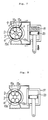
- Fig. 1 two pairs of four planetary rollers 2 having different diameters from one another are externally contiguous to an input shaft 1 of roller shape and internally contiguous to a ring 3 having a predetermined width in its axial direction, and are accommodated within a housing 4 jointly with the ring 3, and this housing 4 is fitted around the outer circumference of the ring 3 with its inner circumference partly kept in contact with the outer circumference of the ring 3.
- One end of the input shaft 1 is connected via a coupling member 8 with a stepping motor 9 fixed to the housing 4, hence if the stepping motor 9 rotates, then the input shaft 1 also rotates, the planetary rollers 2 revolve around the input shaft 1 while rotating about their own axes, and consequently the ring 3 also rotates within the housing 4.
- a fluid inlet 5 extends therethrough in the radial direction, while at another angular position a fluid outlet 6 extends therethrough.
- Fig. 2 is a diagram showing this change while taking the magnitude of this gap clearance X or the degree of the press contact along the ordinate and the revolving angle of the planetary rollers 2 along the abscissa.
- Fig. 4 is a diagram corresponding to that shown in Fig. 2 depicted for this particular embodiment, in which ⁇ 1 represents an angle of the sum of ⁇ 3 in Fig. 3 plus 180°, and ⁇ 2 represents an angle corresponding to ⁇ 2 in Fig. 3.
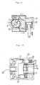
- the valve could be utilized in such manner that the fluid outlet 6a may be used as a fine nozzle having an extremely small bore diameter for feeding fuel for ignition purpose, the fluid outlet 6b may be used as a small flow rate nozzle having a small bore diameter for feeding fuel for idling operation purpose, and the fluid outlet 6c may be used as a large flow rate nozzle for feeding fuel for normal operation purpose.
- the number of the fluid outlets should not be limited to three, but it could be increased or decreased, if desired.
- the planetary rollers 2 and the stepping motor 9 employed the construction that the planetary rollers 2 and the stepping motor 9 are formed separately, and in order to absorb misalignment between the axes of the respective components a coupling member 8 is used, the planetary rollers 2 inherently possess a capability of a bearing, and so, they can also serve as a bearing on one side of the stepping motor 9.
- the third preferred embodiment is a flow control valve constructed from the above-mentioned view point, in which reference numeral 1a designates a rotary shaft serving also as a drive shaft of a stepping motor 9a which will be described later, and planetary rollers 2 perform revolution around this rotary shaft 1a as well as rotation about its own axis.
- the stepping motor 9a consists of a motor rotor 10, motor coil 11, motor housing 12 and a bearing 13 for supporting one end of the rotary shaft 1a as shown in the figure, and a role of another bearing at the other end corresponding to the bearing 13 is played by the afore-mentioned planetary rollers 2.
- this embodiment is basically similar to the first and second preferred embodiments.
- FIGs. 7 to 9 are diagrammatic views in which the planetary roller type servo valve shown in Fig. 6 is connected to an actuator consisting of a cylinder 19 and a piston 20, they are shown by figures corresponding to a cross-section view taken along line A-A in Fig. 6 as viewed in the direction of arrows, and the feed port 15a leading to the actuator and the return port 16b extending from the actuator shown on the cross-section view taken along line B-B in Fig. 6 as viewed in the direction of arrows are depicted by dash lines. It is to be noted that in these figures, for the purpose of facilitating to understand, only essential parts are shown, and the pressurized fluid inlet 14 and the other components are omitted.
- the fluid on the upper side of the piston 20 becomes return fluid, and is exhausted as waste oil 17 via the return port 16a extending from the actuator where the gap clearance X has arrived at and through the gap clearance X.
- rotation of the stepping motor 9a is precisely controlled by easily controllable electric signals, and reciprocating motions of the actuator can be controlled precisely.
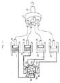
- the pistons 24 are respectively accommodated pistons 24 so as to be able to reciprocate in the axial direction, and the respective tip portions of the pistons 24 are universally coupled to the swash plate 21 via universal couplings.
- the universal couplings 25 are slidable along the coupling surface to the swash plate 21, and even if the output shaft 22 rotates about its own axis, they do not displace in the directions perpendicular to the axis but they displace only in the axial direction according to the degree of inclination of the swash plate 21. Accordingly, the pistons 24 universally coupled to the swash plate 21 would displace within the respective cylinders in the axial direction of the cylinders.
Landscapes
- Engineering & Computer Science (AREA)
- General Engineering & Computer Science (AREA)
- Mechanical Engineering (AREA)
- Chemical & Material Sciences (AREA)
- Combustion & Propulsion (AREA)
- Electrically Driven Valve-Operating Means (AREA)
- Friction Gearing (AREA)
Claims (8)
- Planetenrollen(typ)-Durchflußregelventil, umfassend eine Anzahl von Planetenrollen (2), eine Eingangswelle (1), einen sich innenseitig an die Planetenrollen (2) anschließenden und eine vorbestimmte Breite in seiner Axialrichtung aufweisenden Ring (3), ein um den Ring (3) herum aufgesetztes Gehäuse (4, 4a), dessen Innenumfang teilweise mit dem Außenumfang des Rings (3) in Berührung gehalten und das koaxial und flüssigkeitsdicht gegenüber der Eingangswelle (1) angeordnet ist, einen in einer Winkelstellung des Innenumfangs des Gehäuses (4, 4a) vorgesehenen Fluideinlaß (5, 14) und mindestens einen in einer anderen Winkelstellung des Innenumfangs des Gehäuses (4, 4a) vorgesehenen, von der vorbestimmten Breite des Rings (3) überspannbaren Fluidauslaß (6; 6a, 6b, 6c; 15a, 15b, 15c, 15d), dadurch gekennzeichnet, daß die Rollen (2) voneinander verschiedene Durchmesser aufweisen und sich außenseitig an eine auch als Eingangswelle dienende Rolle (1, 1a, 1b) anschließen.
- Planetenrollen-Durchflußregelventil nach Anspruch 1, wobei die Eingangswelle (1a) auch als DrehWelle (10) einer Antriebsvorrichtung (9a) dient.
- Planetenrollen-Durchflußregelventil nach Anspruch 2, wobei die Planetenrollen (2) auch als Lager für die Dreh-Welle (1a) der Antriebsvorrichtung (9a) dienen.
- Planetenrollen-Durchflußregelventil nach Anspruch 1, wobei der Fluidauslaß (6a, 6b, 6c; 15a, 15b, 15c, 15d) mehrfach am Innenumfang des Gehäuses (4, 4a) vorgesehen ist.
- Planetenrollen-Durchflußregelventil nach einem der Ansprüche 1 bis 4, wobei das aus dem Fluidauslaß (15a, 15b) austretende Fluid als Arbeitsfluid einem Stelltrieb (19, 20) zuspeisbar ist.
- Planetenrollen-Durchflußregelventil nach einem der Ansprüche 1 bis 4, wobei das aus dem Fluidauslaß (15a, 15b, 15c, 15d) austretende Fluid als Arbeitsfluid einer Taumelscheiben-Rotationsmaschine zuspeisbar ist.
- Planetenrollen-Durchflußregelventil nach einem der Ansprüche 1 bis 4, ferner umfassend eine Umfangsnut (18), die im Gehäuse (4) längs des Umfangs des Rings (3) geformt ist und sich an der Berührungsfläche zwischen dem Gehäuse (4) und dem Ring (3) öffnet, und einen in der Umfangsnut (18) vorgesehenen Dichtring (7b).
- Planetenrollen-Durchflußregelventil nach Anspruch 2, wobei die Antriebsvorrichtung (9) ein Schrittmotor ist.
Applications Claiming Priority (4)
| Application Number | Priority Date | Filing Date | Title |
|---|---|---|---|
| JP76804/90 | 1990-03-28 | ||
| JP7680490 | 1990-03-28 | ||
| JP642191A JP2607754B2 (ja) | 1990-03-28 | 1991-01-23 | 遊星ローラ式流量制御弁 |
| JP6421/91 | 1991-01-23 |
Publications (2)
| Publication Number | Publication Date |
|---|---|
| EP0449225A1 EP0449225A1 (de) | 1991-10-02 |
| EP0449225B1 true EP0449225B1 (de) | 1993-11-10 |
Family
ID=26340556
Family Applications (1)
| Application Number | Title | Priority Date | Filing Date |
|---|---|---|---|
| EP19910104800 Expired - Lifetime EP0449225B1 (de) | 1990-03-28 | 1991-03-26 | Durchflussregelventil vom Planetenrollen-Typ |
Country Status (4)
| Country | Link |
|---|---|
| US (1) | US5096157A (de) |
| EP (1) | EP0449225B1 (de) |
| JP (1) | JP2607754B2 (de) |
| DE (1) | DE69100608T2 (de) |
Families Citing this family (6)
| Publication number | Priority date | Publication date | Assignee | Title |
|---|---|---|---|---|
| FR2685384A1 (fr) * | 1991-12-18 | 1993-06-25 | Snecma | Systeme d'alimentation en carburant des injecteurs d'une turbomachine. |
| US6962320B2 (en) * | 2002-12-12 | 2005-11-08 | Sankyo Seiki Mfg. Co., Ltd. | Flow control device |
| EP1477873B1 (de) | 2003-05-12 | 2013-09-11 | WIKA Alexander Wiegand GmbH & Co.KG | Druckregelungssystem |
| JP4817671B2 (ja) * | 2005-02-16 | 2011-11-16 | 株式会社不二工機 | 減速装置付電動弁 |
| JP5693211B2 (ja) * | 2010-12-27 | 2015-04-01 | 株式会社マキタ | 作業工具 |
| US20230132012A1 (en) * | 2020-04-30 | 2023-04-27 | Vanderbilt University | Vertical-via rotary valves, microbioreactors and applications of same |
Family Cites Families (6)
| Publication number | Priority date | Publication date | Assignee | Title |
|---|---|---|---|---|
| DE929406C (de) * | 1954-04-24 | 1955-06-27 | Victor Donald Grant | Absperrhahn mit einem im Hahngehaeuse befestigten roehrenfoermigen Verschlussglied aus Gummi und einem in dem Verschlussglied drehbar angeordneten Hahnkueken |
| GB912831A (en) * | 1958-02-26 | 1962-12-12 | United Shoe Machinery Corp | Improvements in or relating to valve devices |
| DE1833069U (de) * | 1961-04-11 | 1961-06-15 | Birut Waechtersbacher Kunststo | Treibstoff-hahn. |
| FR1448737A (fr) * | 1964-03-21 | 1966-03-18 | Robinet à manchon | |
| US4056292A (en) * | 1976-08-02 | 1977-11-01 | Traut Earl W | Linear rolling contact devices |
| US4718453A (en) * | 1987-02-06 | 1988-01-12 | Bergstrom Manufacturing Co. | Rotary valve |
-
1991
- 1991-01-23 JP JP642191A patent/JP2607754B2/ja not_active Expired - Lifetime
- 1991-03-26 EP EP19910104800 patent/EP0449225B1/de not_active Expired - Lifetime
- 1991-03-26 DE DE91104800T patent/DE69100608T2/de not_active Expired - Fee Related
- 1991-03-27 US US07/675,257 patent/US5096157A/en not_active Expired - Lifetime
Also Published As
| Publication number | Publication date |
|---|---|
| EP0449225A1 (de) | 1991-10-02 |
| DE69100608T2 (de) | 1994-05-11 |
| US5096157A (en) | 1992-03-17 |
| JPH04211774A (ja) | 1992-08-03 |
| JP2607754B2 (ja) | 1997-05-07 |
| DE69100608D1 (de) | 1993-12-16 |
Similar Documents
| Publication | Publication Date | Title |
|---|---|---|
| US5669343A (en) | Valve timing control system for internal combustion engine | |
| CA2219062C (en) | Infinitely variable ring gear pump | |
| EP0147209A2 (de) | Phasenwechselungsvorrichtung für Maschinenanordnungen | |
| CN1266473A (zh) | 相对于传动轮改变轴的相对旋转位置的装置 | |
| EP0015127B1 (de) | Hydraulik-Einheit mit einem Motor und einer Pumpe | |
| RU2142590C1 (ru) | Гидравлический привод с переменной скоростью | |
| JP4212065B2 (ja) | 1:1比率のロックアップクラッチを備える連続可変油圧トランスミッション | |
| US4977816A (en) | Hydraulic motor control system with rotating servo-valve | |
| US5096157A (en) | Planetary roller type flow control valve | |
| KR100398846B1 (ko) | 연속가변유체정역학적트랜스미션 | |
| EP1634131A1 (de) | Flüssigkeits-strömungsregeleinrichtung und dynamometer-testeinrichtung | |
| US5083473A (en) | Ratio control system for toroidal continuously variable transmission | |
| CN111828694B (zh) | 具有被集成到连接板中的阀芯的轴向活塞机 | |
| SE470426B (sv) | Anordning för momentöverföring mellan två roterbara axlar | |
| DE19740553B4 (de) | Differential-Hydraulikmotor | |
| US5394698A (en) | Hydraulic transmission apparatus | |
| US20090151551A1 (en) | Hydraulic Motor Having Radial Cylinders and Continuous Variable Displacement | |
| US4891944A (en) | Hydraulically operated continuously variable transmission | |
| WO1987000590A1 (en) | Rotary actuator | |
| US6092455A (en) | Hydraulic pressure transformer | |
| JPH0229553B2 (de) | ||
| US20020078686A1 (en) | Hydraulic pressure transformer | |
| US4352319A (en) | Positive control for hydrostatic motors, especially radial piston motors | |
| WO1991019902A1 (en) | Hydraulic rotary radial piston pumps | |
| JPH061070B2 (ja) | 回転形流体エネルギ変換機 |
Legal Events
| Date | Code | Title | Description |
|---|---|---|---|
| PUAI | Public reference made under article 153(3) epc to a published international application that has entered the european phase |
Free format text: ORIGINAL CODE: 0009012 |
|
| 17P | Request for examination filed |
Effective date: 19910423 |
|
| AK | Designated contracting states |
Kind code of ref document: A1 Designated state(s): DE GB |
|
| 17Q | First examination report despatched |
Effective date: 19921222 |
|
| GRAA | (expected) grant |
Free format text: ORIGINAL CODE: 0009210 |
|
| AK | Designated contracting states |
Kind code of ref document: B1 Designated state(s): DE GB |
|
| REF | Corresponds to: |
Ref document number: 69100608 Country of ref document: DE Date of ref document: 19931216 |
|
| PLBE | No opposition filed within time limit |
Free format text: ORIGINAL CODE: 0009261 |
|
| STAA | Information on the status of an ep patent application or granted ep patent |
Free format text: STATUS: NO OPPOSITION FILED WITHIN TIME LIMIT |
|
| 26N | No opposition filed | ||
| REG | Reference to a national code |
Ref country code: GB Ref legal event code: IF02 |
|
| PGFP | Annual fee paid to national office [announced via postgrant information from national office to epo] |
Ref country code: DE Payment date: 20050324 Year of fee payment: 15 |
|
| PG25 | Lapsed in a contracting state [announced via postgrant information from national office to epo] |
Ref country code: DE Free format text: LAPSE BECAUSE OF NON-PAYMENT OF DUE FEES Effective date: 20061003 |
|
| PGFP | Annual fee paid to national office [announced via postgrant information from national office to epo] |
Ref country code: GB Payment date: 20100322 Year of fee payment: 20 |
|
| REG | Reference to a national code |
Ref country code: GB Ref legal event code: PE20 Expiry date: 20110325 |
|
| PG25 | Lapsed in a contracting state [announced via postgrant information from national office to epo] |
Ref country code: GB Free format text: LAPSE BECAUSE OF EXPIRATION OF PROTECTION Effective date: 20110325 |