EP0449266A2 - Ein auf einem Gabelstapler montiertes System, dass eine sichere Kraftübertragung auf eine Lastmesszelle erlaubt - Google Patents
Ein auf einem Gabelstapler montiertes System, dass eine sichere Kraftübertragung auf eine Lastmesszelle erlaubt Download PDFInfo
- Publication number
- EP0449266A2 EP0449266A2 EP91104901A EP91104901A EP0449266A2 EP 0449266 A2 EP0449266 A2 EP 0449266A2 EP 91104901 A EP91104901 A EP 91104901A EP 91104901 A EP91104901 A EP 91104901A EP 0449266 A2 EP0449266 A2 EP 0449266A2
- Authority
- EP
- European Patent Office
- Prior art keywords
- truck
- load cell
- force
- fork lift
- system providing
- Prior art date
- Legal status (The legal status is an assumption and is not a legal conclusion. Google has not performed a legal analysis and makes no representation as to the accuracy of the status listed.)
- Withdrawn
Links
- 230000005540 biological transmission Effects 0.000 title claims description 11
- 230000007246 mechanism Effects 0.000 description 3
- 230000035939 shock Effects 0.000 description 3
- 238000005303 weighing Methods 0.000 description 3
- 230000008901 benefit Effects 0.000 description 2
- 230000000694 effects Effects 0.000 description 2
- 238000010348 incorporation Methods 0.000 description 2
- 230000009471 action Effects 0.000 description 1
- 230000020411 cell activation Effects 0.000 description 1
- 238000000034 method Methods 0.000 description 1
- 230000002265 prevention Effects 0.000 description 1
- 125000006850 spacer group Chemical group 0.000 description 1
Images






Classifications
-
- B—PERFORMING OPERATIONS; TRANSPORTING
- B66—HOISTING; LIFTING; HAULING
- B66F—HOISTING, LIFTING, HAULING OR PUSHING, NOT OTHERWISE PROVIDED FOR, e.g. DEVICES WHICH APPLY A LIFTING OR PUSHING FORCE DIRECTLY TO THE SURFACE OF A LOAD
- B66F17/00—Safety devices, e.g. for limiting or indicating lifting force
- B66F17/003—Safety devices, e.g. for limiting or indicating lifting force for fork-lift trucks
-
- G—PHYSICS
- G01—MEASURING; TESTING
- G01G—WEIGHING
- G01G19/00—Weighing apparatus or methods adapted for special purposes not provided for in the preceding groups
- G01G19/08—Weighing apparatus or methods adapted for special purposes not provided for in the preceding groups for incorporation in vehicles
- G01G19/083—Weighing apparatus or methods adapted for special purposes not provided for in the preceding groups for incorporation in vehicles lift truck scale
-
- G—PHYSICS
- G01—MEASURING; TESTING
- G01G—WEIGHING
- G01G21/00—Details of weighing apparatus
- G01G21/24—Guides or linkages for ensuring parallel motion of the weigh-pans
- G01G21/241—Guides or linkages for ensuring parallel motion of the weigh-pans combined with knife-edge bearings
Definitions
- This invention patent describes a system for the transmission of force to the load cell in a fork lift truck offering advantages over the methods as currently known.
- load cells in fork lift trucks so as to signal the weight of the load carried by the arms of the fork, similarly combining the weighing and the handling operations of the load.
- the system functions by providing that each of the fork arms is so connected to the load transmission mechanism that the load is communicated to the load cell by means of an interconnection between the arm actuating on the cell and the various members coupled up to the fork arms of the fork lift truck.
- This present invention patent provides a solution to the problem in the form of the incorporation of a system of load cell activation through an assembly of knife pivots in parallelogram form which are mutually interconnected so as to produce a single force application to the load cell, in that only the forces on a vertical axis are transmitted to hte cell while through the action of the parallelogram layout the transverse forces are not transmitted, but cause a deformation of the parallelogram system.
- Figure 1 is a plan a full section view of the safety system as described in this patent.
- Figure 2 is a plan view corresponding to figure 1.
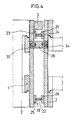
- Figures 3 and 4 are respectively views on a cross section III-III and IV-IV in figure 1, corresponding to hte safety parallelogram layout.
- FIGS 5 and 6 are respectively details in section on the planes V-V and VI-VI.
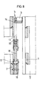
- Figures 7 and 8 are respectively sections on the planes VII -VII and VIII-VIII showing the bearings of the connecting cross member of the parallelograms.
- Figures 9 and 10 show respectively the cross sections on planes IX-IX and X-X of the other cross members and a lateral view of one of the parallelograms.
- Figures 11 and 12 are respectively sections on planes XI-XI and XII-XII from figure 1.
- Figure 13 is a plan view in partial section of an alternative arrangement of the safety and distribution system
- Figures 14,15 and 16 are details corresponding to the adjustment and protection devices.
- Figures 17 and 18 show in plan and in section an alternative arrangement of the fork connections of the truck.
- the connection between the load side -1-, connected to the arms of the fork of the truck and the side -2- of the support or that connected to the truck itself is provided by means of an intermediate bridge structure -3- having three principle points of support 4,5 and 6 which as can be seen in figures 7 and 9 are in the form of frames-7-and -8- connected by a cross member -3- through respectively knife and bearing pivots -9- and -10- in the upper part and -11- and -12- In the lower part, thus transmitting the load held on the forks of the truck to the intermediate support point -5-, in figure 8 in which the frame -13- is seen to be held to the cross member by the knife bearing -14- and at the lower end by the other knife bearing -15- and teansmits the load to on intermediate plate -16- which in turn is connected through a pin -17- to the load cell -18- which signals the load.
- Two articulated parallelograms, with knife bearing joints disposed transversally, numbered -19- and -20- are comprised as in figure 4, of, twin knife bearings -21- and -22- respectively upper and lower, carried on their bearing blocks -23- and -24-, and, -25- and -26- on the side corresponding to the load or connection to the truck.
- Short transverse cross members 27,28 and 29 for the parallelogram -19- and 30,31 and 32 for the parallelogram -20- are fixed respectively to their corresponding transverse pins such as -33- and -34-shown in Figure 4, having other intermediate points of support in the form of knife edge bearings.
- Figures 1 and 11 show adjustment screws with their locking nuts -37- and -38- for adjusting the position of the extension of the cross member -39-
- a pin or dowel -40- is fitted between the projecting wings -41- and -42- passing through a hole in the expansion -43- with plenty of clearance and providing a safety means.
- Figures 13,14,15 and 16 show a variation in which the knife edge bearings which provide protection against the effect of lateral shock, -44- and -45- are fitted laterally , that is to say on the outer side of the components -19- and -20-.
- the devices for protection and adjustment can be provided, as seen in the drawings, by dowel pins -46- end -47- fitted with clearance assuring the prevention of breakage of the transverse pins -33-and -34-, simultaneously connecting up to the adjustment devices by means of the pairs of bolts -46-49-and -50-51- which operate on the items -52- and -53-.
- FIG. 17 and 16 Also provided in the patent is a variant for the arms -2- holding to the truck.
- This variant takes the form shown in figure 17 and 16 in that the upper and lower places -54- and -55- respectively establish the slot width between the items -56- and -57- of the truck by means of plates -58- and -59- in figure 17 which are detachable, these being fitted by means of bolts with intermediate spacers -60- which permit the items -58- and -59- to have their spacing apart adjusted to compensate for any deformation of the structure of the truck in the course of its use.
Landscapes
- Physics & Mathematics (AREA)
- General Physics & Mathematics (AREA)
- Life Sciences & Earth Sciences (AREA)
- Engineering & Computer Science (AREA)
- Geology (AREA)
- Mechanical Engineering (AREA)
- Structural Engineering (AREA)
- Forklifts And Lifting Vehicles (AREA)
- Handcart (AREA)
Applications Claiming Priority (2)
| Application Number | Priority Date | Filing Date | Title |
|---|---|---|---|
| ES9000895A ES2024110A6 (es) | 1990-03-29 | 1990-03-29 | Sistema de seguridad para la transmision de esfuerzos a la celula de carga de una carretilla elevadora. |
| ES9000895 | 1990-03-29 |
Publications (2)
| Publication Number | Publication Date |
|---|---|
| EP0449266A2 true EP0449266A2 (de) | 1991-10-02 |
| EP0449266A3 EP0449266A3 (en) | 1992-11-19 |
Family
ID=8266622
Family Applications (1)
| Application Number | Title | Priority Date | Filing Date |
|---|---|---|---|
| EP19910104901 Withdrawn EP0449266A3 (en) | 1990-03-29 | 1991-03-27 | A system providing a safe transmission of force to the load cell in a fork lift truck |
Country Status (3)
| Country | Link |
|---|---|
| EP (1) | EP0449266A3 (de) |
| ES (1) | ES2024110A6 (de) |
| PT (1) | PT97162A (de) |
Cited By (2)
| Publication number | Priority date | Publication date | Assignee | Title |
|---|---|---|---|---|
| GR1002999B (el) * | 1997-09-02 | 1998-10-27 | Τοποθετηση μηχανισμου ζυγισης σε ανυψωτικο οχημα παντος τυπου | |
| CN114729833A (zh) * | 2019-11-18 | 2022-07-08 | 赛多利斯实验室仪器有限责任两合公司 | 单体式称重系统和其制造方法 |
Family Cites Families (7)
| Publication number | Priority date | Publication date | Assignee | Title |
|---|---|---|---|---|
| US2850181A (en) * | 1953-11-27 | 1958-09-02 | Union Metal Mfg Co | Scale for lift truck or the like |
| US3062308A (en) * | 1958-05-16 | 1962-11-06 | Union Metal Mfg Co | Lift truck scale mechanisms |
| US3066807A (en) * | 1961-04-19 | 1962-12-04 | Elwell Parker Electric Co | Industrial truck |
| FR1417617A (fr) * | 1964-12-15 | 1965-11-12 | Mepag Ag | Balance de précision |
| FR2229576A1 (en) * | 1973-05-16 | 1974-12-13 | Odru Robert | Fork lift truck with weighing device - has conventional yard arm weighing device fitted to loading platform |
| DD153989A3 (de) * | 1980-05-27 | 1982-02-17 | Siegfried Honecker | Praezisionswaegeeinrichtung fuer lange stabaehnliche lasten |
| DE3744194A1 (de) * | 1987-12-24 | 1989-07-06 | Pfreundt Gmbh Waege Und Foerde | Gabelstapler mit waegeeinrichtung |
-
1990
- 1990-03-29 ES ES9000895A patent/ES2024110A6/es not_active Expired - Lifetime
-
1991
- 1991-03-27 PT PT9716291A patent/PT97162A/pt not_active Application Discontinuation
- 1991-03-27 EP EP19910104901 patent/EP0449266A3/en not_active Withdrawn
Cited By (3)
| Publication number | Priority date | Publication date | Assignee | Title |
|---|---|---|---|---|
| GR1002999B (el) * | 1997-09-02 | 1998-10-27 | Τοποθετηση μηχανισμου ζυγισης σε ανυψωτικο οχημα παντος τυπου | |
| CN114729833A (zh) * | 2019-11-18 | 2022-07-08 | 赛多利斯实验室仪器有限责任两合公司 | 单体式称重系统和其制造方法 |
| US12130171B2 (en) | 2019-11-18 | 2024-10-29 | Sartorius Lab Instruments Gmbh & Co. Kg | Monolithic weighing system and method for producing same |
Also Published As
| Publication number | Publication date |
|---|---|
| PT97162A (pt) | 1993-05-31 |
| EP0449266A3 (en) | 1992-11-19 |
| ES2024110A6 (es) | 1992-02-16 |
Similar Documents
| Publication | Publication Date | Title |
|---|---|---|
| US4522548A (en) | Aerial weapons handling trailer | |
| AU744222B2 (en) | A lifting device with a liftable and tiltable platform | |
| US4798512A (en) | Loader boom construction | |
| SK18682001A3 (sk) | Vozík so zdvižnou vidlicou s obmedzeným polomerom otáčania | |
| EP0449266A2 (de) | Ein auf einem Gabelstapler montiertes System, dass eine sichere Kraftübertragung auf eine Lastmesszelle erlaubt | |
| CA1266016A (en) | Apparatus for the overhead transportation of heavy loads on a monorail | |
| US3507512A (en) | Bogie means for vehicles | |
| JPH07505955A (ja) | 第5輪連結器 | |
| US4417634A (en) | Elevating transporter with mechanical drive | |
| US4741549A (en) | Equalizing booster axle system | |
| US4636133A (en) | Heavy load lifting apparatus | |
| EP0499887B1 (de) | Kranwagen | |
| US4498838A (en) | Retention device for a load engaging member | |
| US4456280A (en) | Hydraulic trailer steering system | |
| EP1733994B1 (de) | Hebevorrichtung, sowie eine Hublastmesseinrichtung | |
| CA1230314A (en) | Load handling apparatus | |
| CA1194842A (en) | Industrial truck | |
| US4807902A (en) | Suspension for a wheeled vehicle | |
| EP1048606A1 (de) | Kran | |
| US5308105A (en) | Steerable dual rear axle system for large vehicles | |
| SU1184790A1 (ru) | Грузозахватное устройство дл штучных грузов | |
| CN115057350B (zh) | 一种高稳定性的门式起重机 | |
| SE524121C2 (sv) | Förändring av ytan av ett lastutrymme hos en arbetsmaskin | |
| SU1346464A1 (ru) | Транспортное средство дл перевозки длинномерных грузов | |
| US3338535A (en) | Under carriage with tandem wheels |
Legal Events
| Date | Code | Title | Description |
|---|---|---|---|
| PUAI | Public reference made under article 153(3) epc to a published international application that has entered the european phase |
Free format text: ORIGINAL CODE: 0009012 |
|
| AK | Designated contracting states |
Kind code of ref document: A2 Designated state(s): BE DE ES FR GB IT NL |
|
| PUAL | Search report despatched |
Free format text: ORIGINAL CODE: 0009013 |
|
| AK | Designated contracting states |
Kind code of ref document: A3 Designated state(s): BE DE ES FR GB IT NL |
|
| STAA | Information on the status of an ep patent application or granted ep patent |
Free format text: STATUS: THE APPLICATION IS DEEMED TO BE WITHDRAWN |
|
| 18D | Application deemed to be withdrawn |
Effective date: 19930520 |