EP0449768B1 - Soupape à mise rapide à l'atmosphère - Google Patents
Soupape à mise rapide à l'atmosphère Download PDFInfo
- Publication number
- EP0449768B1 EP0449768B1 EP91810123A EP91810123A EP0449768B1 EP 0449768 B1 EP0449768 B1 EP 0449768B1 EP 91810123 A EP91810123 A EP 91810123A EP 91810123 A EP91810123 A EP 91810123A EP 0449768 B1 EP0449768 B1 EP 0449768B1
- Authority
- EP
- European Patent Office
- Prior art keywords
- valve
- piston
- air vent
- rapid air
- chamber
- Prior art date
- Legal status (The legal status is an assumption and is not a legal conclusion. Google has not performed a legal analysis and makes no representation as to the accuracy of the status listed.)
- Expired - Lifetime
Links
Images

Classifications
-
- F—MECHANICAL ENGINEERING; LIGHTING; HEATING; WEAPONS; BLASTING
- F15—FLUID-PRESSURE ACTUATORS; HYDRAULICS OR PNEUMATICS IN GENERAL
- F15B—SYSTEMS ACTING BY MEANS OF FLUIDS IN GENERAL; FLUID-PRESSURE ACTUATORS, e.g. SERVOMOTORS; DETAILS OF FLUID-PRESSURE SYSTEMS, NOT OTHERWISE PROVIDED FOR
- F15B11/00—Servomotor systems without provision for follow-up action; Circuits therefor
- F15B11/06—Servomotor systems without provision for follow-up action; Circuits therefor involving features specific to the use of a compressible medium, e.g. air, steam
-
- F—MECHANICAL ENGINEERING; LIGHTING; HEATING; WEAPONS; BLASTING
- F16—ENGINEERING ELEMENTS AND UNITS; GENERAL MEASURES FOR PRODUCING AND MAINTAINING EFFECTIVE FUNCTIONING OF MACHINES OR INSTALLATIONS; THERMAL INSULATION IN GENERAL
- F16K—VALVES; TAPS; COCKS; ACTUATING-FLOATS; DEVICES FOR VENTING OR AERATING
- F16K11/00—Multiple-way valves, e.g. mixing valves; Pipe fittings incorporating such valves
- F16K11/10—Multiple-way valves, e.g. mixing valves; Pipe fittings incorporating such valves with two or more closure members not moving as a unit
- F16K11/105—Three-way check or safety valves with two or more closure members
-
- F—MECHANICAL ENGINEERING; LIGHTING; HEATING; WEAPONS; BLASTING
- F16—ENGINEERING ELEMENTS AND UNITS; GENERAL MEASURES FOR PRODUCING AND MAINTAINING EFFECTIVE FUNCTIONING OF MACHINES OR INSTALLATIONS; THERMAL INSULATION IN GENERAL
- F16K—VALVES; TAPS; COCKS; ACTUATING-FLOATS; DEVICES FOR VENTING OR AERATING
- F16K17/00—Safety valves; Equalising valves, e.g. pressure relief valves
- F16K17/18—Safety valves; Equalising valves, e.g. pressure relief valves opening on surplus pressure on either side
- F16K17/19—Equalising valves predominantly for tanks
- F16K17/196—Equalising valves predominantly for tanks spring-loaded
Definitions
- the invention relates to a quick exhaust valve according to the preamble of claim 1.
- a quick exhaust valve according to the preamble of claim 1 is known from DE-B-1 576 088.
- the piston which is reciprocable in the axial direction closes off the axially arranged vent opening with its axial end face.
- the present invention has for its object to develop the quick exhaust valve according to the preamble of claim 1 such that the parts are relatively simple and inexpensive to manufacture.
- this object is achieved by the characterizing features of claim 1, in which the vent opening is arranged transversely to the direction of movement of the piston and can be covered by a peripheral surface of the piston for blocking.
- vent opening achieves an extremely simple valve construction with parts that are relatively easy to manufacture.
- Housing, piston and valve can be manufactured as simple turned parts on automatic lathes.
- the outlet can be arranged both on the same axis as the inlet and at a right angle to it. This enables the quick exhaust valve to be designed both as an ordinary screw connection and as an angle screw connection.
- the chamber is arranged axially and as a cylindrical recess, for. B. is formed as a bore in the valve housing, and the ventilation opening is arranged radially, the piston, when it is acted upon by the working pressure, covers the ventilation opening.
- the chamber and the vent opening are arranged axially, the result is a much simpler construction.
- the piston expediently has a seal in an annular groove on the outlet side, the seal cooperating with a valve seat at the end of the chamber.
- the groove is dimensioned so deep that the seal practically does not touch the wall of the chamber.
- the piston advantageously has a cone on the inlet side, a seal, e.g. an O-ring is provided, which is pressed against the cone and the wall of the chamber by the working pressure.
- the valve has a valve piston which is arranged in a through opening in the piston and which normally closes the through opening, but can be displaced by the working pressure against the force of a valve spring in order to expose the through opening.
- valve piston has an axial recess, an end wall and at least one radial opening arranged on the end wall, and that an annular seal is arranged in a groove on the periphery of the end wall, which seal is in the closed state of the valve through the Force of the valve spring is pressed against the piston to close the through opening.
- the chamber for the piston is expediently a section in a bore with different sections of different diameters.
- the stroke of the piston can be limited on the one hand by a section of smaller diameter and on the other hand by a ring which is preferably inserted in a section of larger diameter.
- the valve housing consists of a first and a second part, e.g. Rotary part, which are arranged at right angles to each other and each have a connection, e.g. have a screw connection.
- the second rotating part of the valve housing for receiving the first part of the valve housing advantageously has a transverse bore, an annular space being formed, and the first part having a radial opening which communicates with the annular space.
- both the first part and the second part have an inlet and that one or the other inlet is optionally closed with a releasable closure, for example a screw closure.
- a releasable closure for example a screw closure.
- the same quick exhaust valve can therefore be used for both connection types.
- the second part of the housing can also be replaced by a sleeve. It is therefore possible to provide a kit for quick exhaust valves, which provides a screw for optionally closing one of two inlets, and a sleeve with which the second part of the housing can be replaced.
- the one-piece housing 11 advantageously consists of a turned part, for example made of brass or an aluminum alloy.
- the housing 11 has two connections, namely an inlet 13 with an internal thread 15 and an outlet 17 with an external thread 19.
- With the reference number 20 is a sealing ring.
- a hexagonal section 21 makes it easier to screw the quick exhaust valve into place, for example into a thread of a pneumatic cylinder.
- the housing 11 has a space 23, preferably in the form of a coaxial bore, with sections 24, 25, 26, 27 of different diameters.
- the section 24 which forms the chamber inlet has the largest diameter.
- the chamber 26 is adjoined by the section 26 which forms the chamber outlet and whose diameter is in turn smaller than that of the chamber 25 and therefore limits the movement of the piston 29 in the direction of the outlet.
- the last section 27, which is located in the area of the thread 19, has the smallest diameter.
- the housing 11 has at least one ventilation opening 31 which e.g. has the shape of an approximately radially arranged bore.
- the vent opening 31, advantageously four offset by 90 degrees from one another, open into an annular space 33 which is formed, for example, by an annular recess on the outside of the housing.
- the annular space 33 is surrounded by a silencer 35, e.g. made of sintered metal chips, enclosed.
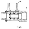
- a connector 36 can also be pushed onto the housing 11 instead of the muffler.
- the piston 29 arranged in the chamber 25 closes the ventilation openings 31 and the outlet 17 in the position shown.
- two seals 32, 34 in the form of O-rings made of an elastomeric material are provided. It can be seen that the piston 29 moves on the one hand by striking the seal 32 on the shoulder 28 and on the other hand by striking the ring 38 is limited at the ring 40.
- the groove 30 is somewhat deeper than the diameter of the ring cross section of the O-ring 32. As a result, the O-ring 32 does not cause any frictional forces when the piston 29 moves. However, the O-ring 32 ensures a secure seal when it occurs when the Working pressure is pressed by the piston 29 against the paragraph 28, which serves as a valve seat.
- the O-ring 34 also causes practically no frictional forces when the piston 29 moves. However, if the piston 29 has been moved into the position shown by the working pressure, the O-ring 34 is pressed by the working pressure into the space between the cone 42 and the wall of the chamber 25. In this way, a good seal of the chamber 25 to the vent opening 31 is achieved. Thanks to the described design of the piston 29 and the seals 32, 34, only a very small force is required to move the piston 29. As a result, the opening pressure of the quick exhaust valve is practically zero.
- the piston 29 has a valve 36 which can be opened by the working pressure.
- the valve 36 has a valve piston 39 arranged in a through opening 37 in the piston 29.
- the valve piston 39 is provided with an axial recess 41, an end wall 43 and at least one approximately radial opening 45 arranged at the end wall.
- An annular seal 49 is arranged in a groove 47 on the periphery of the end wall 43. In the closed state of the valve 36, the annular seal 49 is pressed against the front part of the piston 29 by the force of a valve spring 51 in order to close the passage opening 37.
- the quick exhaust valve works as follows: If compressed air is supplied to the inlet 13, the piston 29 is thereby moved into the position shown, in which it closes the ventilation openings 31. The pressure acting on the valve piston 39 moves it against the force of the valve spring 51, so that air can flow through the through openings 37 into the section 26 and from there to the outlet 17. As soon as On the outlet side practically the same pressure as on the inlet side, the spring 51 closes the valve 36.
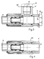
- FIG. 2 differs fundamentally from that of FIG. 1 in that it is designed as an elbow fitting.
- a two-part housing 11 is provided with the parts 11 'and 11''arranged at right angles to one another. These parts are advantageously turned parts, for example made of brass or an aluminum alloy. However, other materials and manufacturing methods that can be used for valves can also be considered here.
- the second rotating part 11 '' has a transverse bore 53 'for receiving the first rotating part 11'.
- An annular space 55 is provided between the first rotating part 11 'and the second rotating part 11''.
- a seal 57 or 58 is provided on each side of the annular space 55.
- the first rotating part 11 ' has at least one radial opening 59 which communicates with the annular space 55.
- the inlet 13 ' with the internal thread 15' in the second part 11 ''.
- a closure 61 for example a cap 61 pressed into the section 24, in order to seal off the space 23 in the region of the section 24.
- the quick exhaust valve of FIG. 2 is designed the same as that of Fig. 1, so that reference can be made to the description there.
- the other inlet is closed with a screw cap 61 and a sealing ring 63.
- the inlet 13 is provided with a thread 15.
- Figure 4 relates to the same embodiment as in Figure 3, but it can be seen that if no angle screwing is necessary, the housing part 11 'of Figure 3 can be replaced by an annular sleeve 63.
- the connecting piece 36 from FIG. 5 can also be used in the other exemplary embodiments.
- the connector 36 allows a line to be connected to the medium escaping from the quick exhaust valve, e.g. to discharge oily air. To keep the number of different parts small, dimensioning is also possible, which allows the housing part 11 'and the connector 36 to be identical.
- the quick exhaust valve consists essentially of the housing 11, the piston 29 and the valve 36 movable in the through opening 37 of the piston.
- the valve 36 has a valve piston 39, which is normally held in the position shown by the valve spring 51 becomes. If compressed air is supplied to the inlet 13, the piston 29 is thereby moved into the position shown, in which it closes the ventilation openings 31.
- the pressure acting on the valve piston 39 moves it against the force of the valve spring 51 the through openings 37 are exposed so that air can flow through them to the outlet 17. If practically the same pressure prevails on the inlet and outlet side, the spring 51 closes the valve 36. If ventilation is to take place, there is no pressure at the inlet 13.
Landscapes
- Engineering & Computer Science (AREA)
- General Engineering & Computer Science (AREA)
- Mechanical Engineering (AREA)
- Physics & Mathematics (AREA)
- Fluid Mechanics (AREA)
- Self-Closing Valves And Venting Or Aerating Valves (AREA)
- Compressor (AREA)
- Safety Valves (AREA)
Claims (16)
- Soupape de purge rapide, comprenant une cage (11) qui comprend une chambre (25) qui comporte une entrée (13), une sortie (17) et au moins un orifice de purge (31), ladite soupape comprenant par ailleurs un piston (29) qui est mobile alternativement en direction axiale dans la chambre, qui peut être exposé du côté de l'entrée à la pression de travail afin de boucher l'orifice de purge (31) et qui peut être exposé du côté de la sortie à la pression de l'air d'évacuation afin de libérer l'orifice de purge (31), ainsi qu'une soupape (36) disposée sur le piston (29) et pouvant être ouverte vers la sortie par la pression de travail, caractérisée en ce que l'orifice de purge (31) est disposé perpendiculairement à la direction de déplacement du piston et peut être recouvert par une surface circonférentielle du piston (29) pour être bouché.
- Soupape de purge rapide selon la revendication 1, caractérisée en ce que la chambre (25) est un évidement cylindrique, par exemple un alésage réalisé dans la cage (11) de la soupape, en ce que la chambre (25) est disposée axialement et l'orifice de purge (31), radialement et, lorsque le piston (29) est exposé à la pression de travail, il recouvre l'orifice de purge (31).
- Soupape de purge rapide selon l'une des revendications 1 ou 2, caractérisée en ce que le piston (29) comporte du côté de la sortie une garniture (32), par exemple un joint torique, placée dans une gorge annulaire (30), ladite garniture coopérant avec un siège de soupape (28) situé à l'extrémité de la chambre (25) et en ce que la gorge (30) est dimensionnée de manière à être suffisamment profonde pour que la garniture (32) ne soit pas en contact avec la paroi de la chambre (25).
- Soupape de purge rapide selon l'une des revendications 1 à 3, caractérisée en ce que le piston (29) comporte un cône (42) du côté de l'entrée et en ce qu'une garniture (34), par exemple un joint torique, qui est prévu à proximité du cône est serrée par la pression de travail contre le cône (42) et la paroi de la chambre (25).
- Soupape de purge rapide selon l'une des revendications 1 à 4, caractérisée en ce que la soupape (36) comprend un piston de soupape (39) qui est disposé dans un trou de traversée (37) du piston (29) et qui normalement obture le trou de traversée (37), mais est déplaçable par la pression de travail contre la force d'un ressort de soupape (51) pour libérer le trou de traversée (37).
- Soupape de purge rapide selon la revendication 5, caractérisée en ce que le piston de soupape (39) comprend un évidement axial (41), une cloison extrême (43) et au moins un trou à peu près radial (45) qui est disposé à proximité de la cloison extrême (43) et en ce qu'une garniture annulaire (49) disposée dans une gorge (47) à la périphérie de la cloison extrême (43) est serrée par la force du ressort de soupape (51) contre le piston (29), lorsque la soupape (36) est à l'état de fermeture, afin d'obturer le trou de traversée (37).
- Soupape de purge rapide selon l'une des revendications 1 à 6, caractérisée en ce que la chambre (25) du piston (29) est une partie d'un alésage (23) comprenant différentes parties (24, 25, 26, 27) de diamètres différents et en ce que la course du piston (29) est limitée d'une part par une partie (26) de petit diamètre et d'autre part par un anneau (40) inséré dans une partie (24) de préférence de diamètre plus grand.
- Soupape de purge rapide selon l'une des revendications 1 à 7, caractérisée en ce que la région de la cage (11) de la soupape dans laquelle se trouve l'orifice de purge (31) est entourée d'un amortisseur de bruit (35), par exemple de copeaux métalliques frittés.
- Soupape de purge rapide selon l'une des revendications 1 à 8, caractérisée en ce que la cage (11) de la soupape est en une pièce et consiste en une pièce tournée qui comporte deux raccords, par exemple des raccords à vis (15, 19).
- Soupape de purge rapide selon l'une des revendications 1 à 8, caractérisée en ce que la cage (11) de la soupape se compose d'une première (11') et d'une seconde (11'') parties, par exemple des pièces tournées, qui sont disposées à angle droit l'une par rapport à l'autre et dont chacune comporte un raccord, par exemple un raccord à vis (19, 15').
- Soupape de purge rapide selon la revendication 10, caractérisée en ce que la seconde partie (11') de la cage (11) de la soupape comporte un trou transversal (53) de logement de la première partie (11') de la cage (11) de la soupape, un espace annulaire (55) étant formé, et en ce que la première partie (11') comporte un trou radial (59) qui communique avec l'espace annulaire (55).
- Soupape de purge rapide selon la revendication 11, caractérisée en ce qu'une garniture (57, 58) est disposée sur chaque côté de l'espace annulaire (55).
- Soupape de purge rapide selon l'une des revendications 10 à 12, caractérisée en ce que l'alésage axial (23) est fermé par un obturateur (61) du côté opposé à celui de la sortie (17) (figures 2 et 3).
- Soupape de purge rapide selon la revendication 12, caractérisée en ce qu'aussi bien la première partie (11') que la seconde partie (11'') comprennent une entrée (13, 13') et en ce que l'une ou l'autre des entrées (13, 13') est fermée par un obturateur amovible (61), par exemple un obturateur à vis.
- Soupape de purge rapide selon l'une des revendications 10 à 12, caractérisée en ce que la seconde partie (11'') est remplaçable sélectivement par une douille (63).
- Soupape de purge rapide selon l'une des revendications 1 à 15, caractérisée en ce que l'orifice de purge (31) est entouré d'un canal annulaire (33) et en ce qu'un amortisseur de bruit (35) ou une pièce de raccord (36) peut être sélectivement disposé au-dessus du canal annulaire.
Applications Claiming Priority (2)
| Application Number | Priority Date | Filing Date | Title |
|---|---|---|---|
| CH106290 | 1990-03-30 | ||
| CH1062/90 | 1990-03-30 |
Publications (2)
| Publication Number | Publication Date |
|---|---|
| EP0449768A1 EP0449768A1 (fr) | 1991-10-02 |
| EP0449768B1 true EP0449768B1 (fr) | 1994-11-23 |
Family
ID=4201566
Family Applications (1)
| Application Number | Title | Priority Date | Filing Date |
|---|---|---|---|
| EP91810123A Expired - Lifetime EP0449768B1 (fr) | 1990-03-30 | 1991-02-25 | Soupape à mise rapide à l'atmosphère |
Country Status (3)
| Country | Link |
|---|---|
| EP (1) | EP0449768B1 (fr) |
| AT (1) | ATE114358T1 (fr) |
| DE (1) | DE59103561D1 (fr) |
Families Citing this family (16)
| Publication number | Priority date | Publication date | Assignee | Title |
|---|---|---|---|---|
| EP0520212B1 (fr) * | 1991-06-24 | 1995-09-13 | Smc Kabushiki Kaisha | Commande de vitesse |
| US5279322A (en) * | 1991-11-14 | 1994-01-18 | Smc Kabushiki Kaisha | Exhaust valve |
| GB9125551D0 (en) * | 1991-11-30 | 1992-01-29 | Appleton Robert P | Mud check valves in drilling apparatus(wells) |
| DE9303048U1 (de) * | 1993-03-03 | 1993-05-13 | Festo KG, 7300 Esslingen | Arbeitszylinder-Anordnung |
| RU2213284C2 (ru) * | 2001-09-20 | 2003-09-27 | ООО "Центр специальной техники "ТРИТОН" | Запорное устройство для аварийного перекрытия трубопровода |
| WO2008009251A1 (fr) * | 2006-07-21 | 2008-01-24 | Ixetic Hückeswagen Gmbh | pompe À vide |
| GB2457497B (en) | 2008-02-15 | 2012-08-08 | Pilot Drilling Control Ltd | Flow stop valve |
| EP2467561B1 (fr) | 2009-08-18 | 2017-03-15 | Pilot Drilling Control Limited | Soupape d'arrêt d'écoulement |
| WO2011066817A2 (fr) * | 2009-12-04 | 2011-06-09 | Ixetic Hückeswagen Gmbh | Pompe à vide |
| IT1400951B1 (it) * | 2010-07-21 | 2013-07-05 | Pneumax Spa | Dispositivo per il silenziamento e la protezione dallo sporco da applicare alle valvole di scarico di fluidi in pressione |
| KR101310435B1 (ko) * | 2010-12-20 | 2013-09-24 | 삼성전기주식회사 | 에너지 저장 장치용 에어 밸브 및 이를 포함하는 에너지 저장 장치 |
| US10737544B2 (en) * | 2017-07-24 | 2020-08-11 | Ford Global Technologies, Llc | Systems and methods to control a suspension of a vehicle |
| IT201900013953A1 (it) * | 2019-08-05 | 2021-02-05 | Rubinetterie Ritmonio S R L | Valvola di sicurezza per riscaldatori d'acqua, in particolare valvola contro sovra-pressioni per scaldabagni |
| DE102019007454A1 (de) * | 2019-10-24 | 2021-04-29 | Kaco Gmbh + Co. Kg | Ventil zum Druckausgleich und/oder zur Notentlüftung eines Behälters, vorzugsweise eines Gehäuses einer Batterie von Elektrofahrzeugen, sowie Behälter mit einem solchen Ventil |
| CN115610398A (zh) * | 2022-09-14 | 2023-01-17 | 东科克诺尔商用车制动技术有限公司 | 一种快放阀 |
| CN121676710B (zh) * | 2026-02-06 | 2026-04-21 | 厦门微能电子科技有限公司 | 一种独立三功能复合式排气阀 |
Family Cites Families (5)
| Publication number | Priority date | Publication date | Assignee | Title |
|---|---|---|---|---|
| FR1423813A (fr) * | 1964-11-20 | 1966-01-07 | Valve de purge rapide | |
| CH541101A (de) * | 1971-03-12 | 1973-08-31 | Crosweller & Co Ltd W | Belüftungsventil |
| AT333408B (de) * | 1974-05-17 | 1976-11-25 | Hoerbiger Ventilwerke Ag | Selbsttatiges druckentlastungsventil |
| US4321940A (en) * | 1981-01-19 | 1982-03-30 | Control Devices, Incorporated | Unloader/check valve |
| CH672946A5 (fr) * | 1986-12-10 | 1990-01-15 | Wirth & Schwaar Fluidtechnik A |
-
1991
- 1991-02-25 DE DE59103561T patent/DE59103561D1/de not_active Expired - Fee Related
- 1991-02-25 EP EP91810123A patent/EP0449768B1/fr not_active Expired - Lifetime
- 1991-02-25 AT AT91810123T patent/ATE114358T1/de not_active IP Right Cessation
Also Published As
| Publication number | Publication date |
|---|---|
| ATE114358T1 (de) | 1994-12-15 |
| DE59103561D1 (de) | 1995-01-05 |
| EP0449768A1 (fr) | 1991-10-02 |
Similar Documents
| Publication | Publication Date | Title |
|---|---|---|
| DE4139178C2 (de) | Drehflügelstoßdämpfer | |
| EP0449768A1 (fr) | Soupape à mise rapide à l'atmosphère | |
| EP0604608B1 (fr) | Robinet d'arret | |
| DE3014690A1 (de) | Magnetisch betaetigtes absperrventil | |
| WO1992014085A1 (fr) | Soupape a cartouche | |
| EP0380754A2 (fr) | Soupape de levage à force équilibrée | |
| EP0606419B1 (fr) | Partie superieure de soupape | |
| DE3831554C2 (de) | Drosselrückschlagventil | |
| DE3338418C2 (fr) | ||
| DE202014101096U1 (de) | Ventiloberteil | |
| DE2012707A1 (de) | Schließvorrichtung für Strömungsmedien, insbesondere für Hochdruck-Flüssigkeiten | |
| EP0112977A1 (fr) | Organe d'arrêt pour fluides agressifs | |
| DE3239930A1 (de) | Hydraulisch steuerbares sperrventil, insbesondere fuer die rohrbruchsicherung | |
| DE102005052385B4 (de) | Druckminderer | |
| DE3007601A1 (de) | Armatur | |
| DE4445588A1 (de) | Membrangesteuertes Differenzdruckventil | |
| EP0857901A2 (fr) | Soupape | |
| EP0329800B1 (fr) | Partie supérieure de vanne | |
| DE3003480C2 (fr) | ||
| DE19714587C1 (de) | Ventil | |
| DE1550468B2 (de) | Doppelsitzventil | |
| WO2021115527A1 (fr) | Dispositif de régulation de pressions d'un milieu d'écoulement à l'aide d'une vanne | |
| DE10358429B4 (de) | Schnellentlüftungsventil | |
| EP1348899B1 (fr) | Soupape coaxiale | |
| DE3002760C2 (fr) |
Legal Events
| Date | Code | Title | Description |
|---|---|---|---|
| PUAI | Public reference made under article 153(3) epc to a published international application that has entered the european phase |
Free format text: ORIGINAL CODE: 0009012 |
|
| AK | Designated contracting states |
Kind code of ref document: A1 Designated state(s): AT CH DE FR IT LI SE |
|
| 17P | Request for examination filed |
Effective date: 19920330 |
|
| 17Q | First examination report despatched |
Effective date: 19930602 |
|
| GRAA | (expected) grant |
Free format text: ORIGINAL CODE: 0009210 |
|
| AK | Designated contracting states |
Kind code of ref document: B1 Designated state(s): AT CH DE FR IT LI SE |
|
| REF | Corresponds to: |
Ref document number: 114358 Country of ref document: AT Date of ref document: 19941215 Kind code of ref document: T |
|
| REF | Corresponds to: |
Ref document number: 59103561 Country of ref document: DE Date of ref document: 19950105 |
|
| REG | Reference to a national code |
Ref country code: CH Ref legal event code: PUE Owner name: PRESS CONTROLS AG RUEMLANG |
|
| RAP2 | Party data changed (patent owner data changed or rights of a patent transferred) |
Owner name: PRESS CONTROLS AG RUEMLANG |
|
| ITF | It: translation for a ep patent filed | ||
| ET | Fr: translation filed | ||
| RAP2 | Party data changed (patent owner data changed or rights of a patent transferred) |
Owner name: PRESS CONTROLS AG RUEMLANG |
|
| PLBE | No opposition filed within time limit |
Free format text: ORIGINAL CODE: 0009261 |
|
| 26N | No opposition filed | ||
| REG | Reference to a national code |
Ref country code: CH Ref legal event code: PUE Owner name: PRESS CONTROLS AG RUEMLANG TRANSFER- NASS MAGNET G |
|
| PGFP | Annual fee paid to national office [announced via postgrant information from national office to epo] |
Ref country code: AT Payment date: 20020110 Year of fee payment: 12 |
|
| PGFP | Annual fee paid to national office [announced via postgrant information from national office to epo] |
Ref country code: SE Payment date: 20020122 Year of fee payment: 12 |
|
| REG | Reference to a national code |
Ref country code: FR Ref legal event code: TP |
|
| PG25 | Lapsed in a contracting state [announced via postgrant information from national office to epo] |
Ref country code: AT Free format text: LAPSE BECAUSE OF NON-PAYMENT OF DUE FEES Effective date: 20030225 |
|
| PG25 | Lapsed in a contracting state [announced via postgrant information from national office to epo] |
Ref country code: SE Free format text: LAPSE BECAUSE OF NON-PAYMENT OF DUE FEES Effective date: 20030226 |
|
| EUG | Se: european patent has lapsed | ||
| PGFP | Annual fee paid to national office [announced via postgrant information from national office to epo] |
Ref country code: FR Payment date: 20060112 Year of fee payment: 16 |
|
| PGFP | Annual fee paid to national office [announced via postgrant information from national office to epo] |
Ref country code: CH Payment date: 20060118 Year of fee payment: 16 |
|
| PGFP | Annual fee paid to national office [announced via postgrant information from national office to epo] |
Ref country code: IT Payment date: 20060228 Year of fee payment: 16 |
|
| PGFP | Annual fee paid to national office [announced via postgrant information from national office to epo] |
Ref country code: DE Payment date: 20060421 Year of fee payment: 16 |
|
| PG25 | Lapsed in a contracting state [announced via postgrant information from national office to epo] |
Ref country code: LI Free format text: LAPSE BECAUSE OF NON-PAYMENT OF DUE FEES Effective date: 20070228 Ref country code: CH Free format text: LAPSE BECAUSE OF NON-PAYMENT OF DUE FEES Effective date: 20070228 |
|
| REG | Reference to a national code |
Ref country code: CH Ref legal event code: PL |
|
| REG | Reference to a national code |
Ref country code: FR Ref legal event code: ST Effective date: 20071030 |
|
| PG25 | Lapsed in a contracting state [announced via postgrant information from national office to epo] |
Ref country code: DE Free format text: LAPSE BECAUSE OF NON-PAYMENT OF DUE FEES Effective date: 20070901 |
|
| PG25 | Lapsed in a contracting state [announced via postgrant information from national office to epo] |
Ref country code: FR Free format text: LAPSE BECAUSE OF NON-PAYMENT OF DUE FEES Effective date: 20070228 |
|
| PG25 | Lapsed in a contracting state [announced via postgrant information from national office to epo] |
Ref country code: IT Free format text: LAPSE BECAUSE OF NON-PAYMENT OF DUE FEES Effective date: 20070225 |