EP0449815B1 - Fahrräder - Google Patents
Fahrräder Download PDFInfo
- Publication number
- EP0449815B1 EP0449815B1 EP89904587A EP89904587A EP0449815B1 EP 0449815 B1 EP0449815 B1 EP 0449815B1 EP 89904587 A EP89904587 A EP 89904587A EP 89904587 A EP89904587 A EP 89904587A EP 0449815 B1 EP0449815 B1 EP 0449815B1
- Authority
- EP
- European Patent Office
- Prior art keywords
- suspension
- main frame
- rod
- wheel
- pedal
- Prior art date
- Legal status (The legal status is an assumption and is not a legal conclusion. Google has not performed a legal analysis and makes no representation as to the accuracy of the status listed.)
- Expired - Lifetime
Links
Images
Classifications
-
- B—PERFORMING OPERATIONS; TRANSPORTING
- B60—VEHICLES IN GENERAL
- B60G—VEHICLE SUSPENSION ARRANGEMENTS
- B60G21/00—Interconnection systems for two or more resiliently-suspended wheels, e.g. for stabilising a vehicle body with respect to acceleration, deceleration or centrifugal forces
- B60G21/02—Interconnection systems for two or more resiliently-suspended wheels, e.g. for stabilising a vehicle body with respect to acceleration, deceleration or centrifugal forces permanently interconnected
- B60G21/04—Interconnection systems for two or more resiliently-suspended wheels, e.g. for stabilising a vehicle body with respect to acceleration, deceleration or centrifugal forces permanently interconnected mechanically
- B60G21/045—Interconnection systems for two or more resiliently-suspended wheels, e.g. for stabilising a vehicle body with respect to acceleration, deceleration or centrifugal forces permanently interconnected mechanically between wheels on different axles on the same side of the vehicle, i.e. the left or the right side
-
- B—PERFORMING OPERATIONS; TRANSPORTING
- B62—LAND VEHICLES FOR TRAVELLING OTHERWISE THAN ON RAILS
- B62K—CYCLES; CYCLE FRAMES; CYCLE STEERING DEVICES; RIDER-OPERATED TERMINAL CONTROLS SPECIALLY ADAPTED FOR CYCLES; CYCLE AXLE SUSPENSIONS; CYCLE SIDECARS, FORECARS, OR THE LIKE
- B62K25/00—Axle suspensions
Definitions
- This invention relates to cycles, particularly pedal bicycles but the teachings of the invention are also applicable to mopeds and tricycles.
- a pedal cycle comprising a main frame, a front suspension displaceably mounted to said main frame, a front wheel rotatably mounted to said front suspension, a rear suspension displaceably mounted to said main frame, a rear wheel rotatably mounted to said rear suspension, a pair of pedals rotatably mounted via a crankaxle to said main frame, and a chain transmission for transmitting drive from said pair of pedals to said rear wheel, characterised in that the rear suspension is pivoted to said main frame at a point above a line extending through said crank axle and the rear wheel axle, and an interconnecting link interconnects said front suspension and said rear suspension so that any load on said front wheel, tending to lift said front wheel by displacement of said front suspension relative to said main frame, applies a force to said interconnecting link which is transmitted by said interconnecting link to said rear suspension for displacing said rear suspension relative to said main frame, with said interconnecting links further acting so that a force applied thereto by said rear suspension,
- the pedal cycle further comprises resilient biassing means for opposing displacement of the interconnecting link in a direction away from the rear suspension and towards the front suspension.
- the interconnecting link comprises a rod which extends through a tubular element of the main frame, which houses at least one compression spring for opposing movement of the rod in the forwardly direction.
- a lost-motion device may be included in the interconnecting link (e.g. in the rod just described) between front and rear suspensions.
- each suspension includes a resilient element independently opposing displacement of that suspension relative to the main frame, and the interconnecting link comprises a cable which interconnects the two suspensions for transmitting a force under tension from one suspension to the other.
- the resilient elements may comprise bodies of rubber or other resilient material which are mounted to the main frame, with a peg projecting from a moving element of the respective suspension and into the respective resilient body.
- the pedal cycle has a main frame structure connecting four parallel bores being points of attachment for the crank axle, the rear suspension pivot, a front suspension pivot and the steering tube pivot.
- the main frame may additionally include a fifth bore being a point of attachment for a lever arm of the interconnection system of the front and rear suspensions.
- the main frame may include another bore being a point of attachment for a brace to the seat tube.
- the main frame may include further bores receiving the resilient bodies referred to above, which resiliently oppose displacement of the respective suspensions.
- the main frame includes a plurality of bores, all parallel to each other, for mounting or attachment to the frame of the necessary components and assemblies of the cycle, the frame lends itself to being moulded, the two halves of the mould being separated along an axis perpendicular to the plane of the frame.
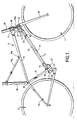
- a pedal bicycle comprising front and rear wheels 1, 2 and a main frame 3.
- the main frame 3 comprises an upper, straight element 10, a short, generally vertical element 12 extending downwards from the front end of the element 10, a longer straight element 14 extending downwardly and forwardly from the rear end of the element 10, and a lower straight element 16 which extends forwardly and upwardly from the lower end of element 14 to the lower end of element 12.
- the main frame further comprises an upright seat tube 18 extending from the rear end of the element 10.
- the main frame may be constructed of tubular metal or it may be die-cast.
- the main frame is formed with six through-bores all parallel to each other and perpendicular to the plane containing the main frame, these six bores being at 20 (at the junction of elements 10 and 14), at 21 (junction of elements 10 and 12), at 22 (adjacent the lower end of element 12), at 23 (adjacent the junction of elements 14 and 16), at 24 (on a projection 25 extending downwardly and rearwardly from the junction of elements 14 and 16,) and at 10a (to form a point of attachment for seat tube brace 18a).
- the bore 23 serves to mount the crank axle, whilst the functions of bores 20-22 and 24 will be described below.
- the rear wheel 2 is rotatably mounted to a rear suspension 26 which comprises a bifurcated V-shape sub-frame, the free end of the upper elements being pivoted to the main frame by a bearing extending through the bore 20, at which point the seat tube 18 is also pivotally mounted.
- the free ends of the lower elements of the sub-frame are pivoted to one end of a lever arm 27, which is pivoted intermediate its ends to the extension 25 of the main frame, using the bore 24.
- the rear suspension pivot 20 is above the transmission line i.e. the line from the crank axle 23 to the rear wheel axle.
- the front wheel 1 is rotatably mounted to the front forks 28 of the bicycle.
- the front forks 28 are fixed to the lower end of a steering column 28a which has a longitudinally splined upper end fitted into a similarly splined lower end of a steering tube 29, to which the handlebars are fitted.
- the steering column 28a is therefore slidable relative to the steering tube 29 but turns therewith.
- the steering tube 29 passes through a tubular collar 30 and is mounted thereto on bearings giving axial and radial support yet permitting turning of the steering tube 29.
- a front suspension of the bicycle comprises a crank element 31 pivotally mounted to the main frame 3 using the bore 22.
- a leg of the crank which projects forwardly from the pivotal mounting at 22 is pivoted to a tubular collar 32 on the lower end of the steering column 28a.
- the front and rear suspensions of the bicycle are interconnectd by a rod 33 extending through the lower element 16 of the main frame: this rod 33 may be continuous or it may include a lost-motion device 34 which will be described with reference to Figure 2.
- the rear end of rod 33 emerges from the main frame and is pivoted to the upper end of the lever arm 27.
- the forward end of the rod 33 emerges from the main frame and is pivoted to the free end of a leg of the crank 31 which projects downwardly from its pivot 22.
- Compression springs 35, 36 are mounted in the main frame element 16 adjacent its top and bottom ends respectively, encircling the rod 33. Washers 37 and 38 are fixed to the rod 33 and serve to compress spring 35 or 36 upon movement of the rod 33 forwardly.
- the pedal cycle of Figure 1 is of variable geometry by reason of the front and rear suspensions being movable relative to the main frame.
- the suspension components may be replaced by others of different size and shape to allow bicycles of selected geometry to be built using the one design of main frame.
- the front and rear suspensions are interconnected by the rod 33, so that movement of one suspension is transmitted to the other.
- this movement pivots the crank 31 so as to pull forwardly on the rod 33, with the effect of moving the rear wheel upwards (pivoting its sub-frame about 20).
- this tends to move the rear wheel upwards and push the rod 33 forwardly, in turn pivoting crank 31 so as to lift the front wheel.
- These movements are opposed resiliently by the compression springs 35, 36.
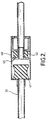
- the rod 33 which interconnects the front and rear suspension may include a lost-motion device 34 as shown in Figure 2.
- This device comprises a tubular housing 40 with the rear portion of rod 33 attached to one of its ends, with a rubber block 41 disposed within the housing 40 at this end.
- the front portion of the rod 33 is slidable in the front end of the housing 40 and carries a rubber block 42. It will be appreciated that in response to a load from the rear suspension displacing the rear portion of rod 33 forwardly a certain amount of this movement must take place before rubber block 41 abuts the flange 43 to commence forward movement of the front portion of rod 33.
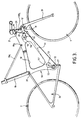
- FIG. 3 shows another embodiment of pedal bicycle in accordance with this invention, and exhibits a number of modifications relative to the bicycle shown in Figure 1.
- the frame 50 comprises a unitary, generally flat structure, optionally formed with a central aperture 51 to save weight.
- the frame 50 may be die-cast from metal or moulded from appropriate synthetic plastics e.g. reinforced with carbon fibre.
- the frame 50 is formed with the transverse bores 20, 10a, 21 and 22 for the same purposes as in the bicycle of Figure 1: a further transverse bore 52 serves as a mounting for the crank axle and also for the pivotal lever 27.
- Two further transverse bores 53 and 54 are formed through the frame and mount circular rubber bodies 55, 56.
- a cable 59 extends between the lever 27 and the crank 31 to transmit a force under tension from one suspension to the other, in similar manner as described above in relation to the bicycle of Figure 1.
Landscapes
- Engineering & Computer Science (AREA)
- Mechanical Engineering (AREA)
- Axle Suspensions And Sidecars For Cycles (AREA)
- Saccharide Compounds (AREA)
- Pharmaceuticals Containing Other Organic And Inorganic Compounds (AREA)
Claims (6)
- Ein Pedalfahrrad mit einem Hauptrahmen (3), einer verschiebbar an dem Hauptrahmen (3) angebrachten vorderen Aufhängung (28,31,32), einem drehbar an der vorderen Aufhängung (28,31,32) angebrachten Vorderrad (1), einer verschiebbar an dem Hauptrahmen (3) angebrachten hinteren Aufhängung (26), einem drehbar an der hinteren Aufhängung (26) angebrachten Hinterrad (2), einem über eine Kurbelachse an dem Hauptrahmen drehbar gelagerten Paar von Pedalen und einer Kettentransmission zur Übertragung von Antriebskraft von dem Pedalpaar zu dem Hinterrad (2), dadurch gekennzeichnet, daß die hintere Aufhängung (26) an einem oberhalb einer durch die Kurbelachse und die hintere Radachse verlaufende Linie liegenden Punkt (20) mit dem Hauptrahmen schwenkbar verbunden ist und ein Verbindungsglied (33) die vordere Aufhängung (28,31,32) und die hintere Aufhängung (26) derart miteinander verbindet, daß irgendeine Belastung des Vorderrads (1), die dazu neigt, das Vorderrad (1) durch Verschiebung der vorderen Aufhängung (28,31,32) im Verhältnis zu dem Hauptrahmen (3) anzuheben, auf das Verbindungsglied eine Kraft ausübt, die durch das Verbindungsglied (33) der hinteren Aufhängung (26) mitgeteilt wird, um die hintere Aufhängung (26) im Verhältnis zum Hauptrahmen (3) zu verschieben, wobei das Verbindungsglied (33) ferner derart wirkt, daß eine Kraft, die von der hinteren Aufhängung (26) infolge der in der Kettentransmission entwickelten Spannung darauf ausgeübt wird, wenn der Fahrer ein vorderes Pedal des Pedalpaars niedertritt, im wesentlichen vollständig auf die vordere Aufhängung (28,31,32) entgegen einer Kraft übertragen wird, die auf das Verbindungsglied (33) infolge einer Last ausgeübt wird, die auf die vordere Aufhängung dadurch aufgebracht wird, daß der Fahrer das vordere Pedal niedertritt.
- Ein Pedalfahrrad nach Anspruch 1, gekennzeichnet durch elastische Mittel (35,36) zur Erzeugung einer Gegenkraft, die einer Verschiebung des Verbindungsglieds (33) in einer Richtung weg von der hinteren Aufhängung (26) und zu der vorderen Aufhängung hin entgegenwirkt.
- Ein Pedalfahrrad nach Anspruch 2, dadurch gekennzeichnet, daß das Verbindungsglied (33) eine in Längsrichtung im Verhältnis zu dem Hauptrahmen bewegliche Stange umfaßt, wobei die Mittel (35,36) zur Erzeugung einer Gegenkraft zwischen der Stange (33) und dem Hauptrahmen (3) wirken, um einer Längsverschiebung der Stange (33) in der angegebenen Richtung entgegenzuwirken.
- Ein Pedalfahrrad nach Anspruch 3, dadurch gekennzeichnet, daß in die Stange (33) eine Leerhubeinrichtung (34) eingeschlossen ist.
- Ein Pedalfahrrad nach Anspruch 2, dadurch gekennzeichnet, daß jede Aufhängung ein elastisches Element (55,56) einschließt, das einer Verschiebung jeweils dieser Aufhängung gegenüber dem Hauptrahmen (3) entgegenwirkt, und daß das Verbindungsglied ein Seil (59) umfaßt, das die beiden Aufhängungen miteinander verbindet, um Zugkraft von einer Aufhängung auf die andere zu übertragen.
- Ein Pedalfahrrad nach einem der vorhergehenden Ansprüche, dadurch gekennzeichnet, daß der Hauptrahmen (3) wenigstens vier parallele Querbohrungen (23,20,22,21) als Anbringungsstellen für die Kurbelachse, die Schwenklagerung für die hintere Aufhängung, eine Schwenklagerung für die vordere Aufhängung und eine Schwenklagerung für ein Lenkrohr umfaßt.
Applications Claiming Priority (5)
| Application Number | Priority Date | Filing Date | Title |
|---|---|---|---|
| GB888808178A GB8808178D0 (en) | 1988-04-08 | 1988-04-08 | Improvements to pedal cycles |
| GB8808178 | 1988-04-08 | ||
| GB888826905A GB8826905D0 (en) | 1988-04-08 | 1988-11-17 | Cycles |
| GB8826905 | 1988-11-17 | ||
| PCT/GB1989/000352 WO1989009718A1 (en) | 1988-04-08 | 1989-04-05 | Cycles |
Publications (2)
| Publication Number | Publication Date |
|---|---|
| EP0449815A1 EP0449815A1 (de) | 1991-10-09 |
| EP0449815B1 true EP0449815B1 (de) | 1994-12-14 |
Family
ID=26293744
Family Applications (1)
| Application Number | Title | Priority Date | Filing Date |
|---|---|---|---|
| EP89904587A Expired - Lifetime EP0449815B1 (de) | 1988-04-08 | 1989-04-05 | Fahrräder |
Country Status (5)
| Country | Link |
|---|---|
| EP (1) | EP0449815B1 (de) |
| JP (1) | JPH03503624A (de) |
| AT (1) | ATE115486T1 (de) |
| DE (1) | DE68920052T2 (de) |
| WO (1) | WO1989009718A1 (de) |
Families Citing this family (7)
| Publication number | Priority date | Publication date | Assignee | Title |
|---|---|---|---|---|
| US5201537B1 (en) * | 1991-06-11 | 2000-02-29 | Cannondale Corp | Bicycle frame |
| US5658001A (en) * | 1993-03-29 | 1997-08-19 | Blanchard; Pierre | Bicycle with a long stroke suspension |
| DE4317612A1 (de) * | 1993-05-27 | 1994-12-01 | Dietrich Gerhard Ellsaeser | Manuell adaptive Federung mit Verstellarmaturen für Fahrräder |
| GB2280879A (en) * | 1993-08-10 | 1995-02-15 | George Carr Milburn | Bicycle suspension |
| DE19603950A1 (de) * | 1996-02-05 | 1997-08-07 | Sachsen Zweirad Gmbh | Zweiradfederungssystem |
| US6203042B1 (en) | 1998-02-20 | 2001-03-20 | Trek Bicycle Corporation | Bicycle rear suspension system providing relative rearward motion of rear axle |
| US6164676A (en) * | 1998-02-20 | 2000-12-26 | Trek Bicycle Corporation | Variable reduction cross-linkage for rear suspension bicycle |
Family Cites Families (4)
| Publication number | Priority date | Publication date | Assignee | Title |
|---|---|---|---|---|
| BE402119A (de) * | 1932-10-14 | |||
| US2950122A (en) * | 1958-10-30 | 1960-08-23 | Erickson Roy | Stabilizing mechanism for automotive vehicle |
| JPS602230B2 (ja) * | 1980-12-22 | 1985-01-19 | 川崎重工業株式会社 | 自動2輪車のアンチノ−ズダイブ装置 |
| US4583612A (en) * | 1984-07-19 | 1986-04-22 | Parker James G | Anti-pitch system for a motorcycle |
-
1989
- 1989-04-05 WO PCT/GB1989/000352 patent/WO1989009718A1/en not_active Ceased
- 1989-04-05 EP EP89904587A patent/EP0449815B1/de not_active Expired - Lifetime
- 1989-04-05 JP JP1504186A patent/JPH03503624A/ja active Pending
- 1989-04-05 DE DE68920052T patent/DE68920052T2/de not_active Expired - Fee Related
- 1989-04-05 AT AT89904587T patent/ATE115486T1/de active
Also Published As
| Publication number | Publication date |
|---|---|
| WO1989009718A1 (en) | 1989-10-19 |
| DE68920052T2 (de) | 1995-05-18 |
| DE68920052D1 (de) | 1995-01-26 |
| ATE115486T1 (de) | 1994-12-15 |
| JPH03503624A (ja) | 1991-08-15 |
| EP0449815A1 (de) | 1991-10-09 |
Similar Documents
| Publication | Publication Date | Title |
|---|---|---|
| US5417445A (en) | Cycles | |
| EP1086014B1 (de) | Fahrrad mit kurbelaufhängungssystem | |
| US5957473A (en) | Rear suspension bicycle | |
| US4789174A (en) | Suspension bicycle | |
| US5611557A (en) | Bicycle suspension system | |
| US7210695B2 (en) | Suspension systems | |
| US4997197A (en) | Soft suspension bicycle | |
| CA2114960C (en) | Derailleur mounting assembly for a bicycle | |
| CA1207352A (en) | Tricycle | |
| KR100489771B1 (ko) | 차량의 스윙 아암식 현가(懸架) 장치 | |
| US6669218B1 (en) | Bicycle front fork assembly | |
| US6073950A (en) | Bicycle with crank assembly suspension system | |
| US5553880A (en) | Energy-absorber for a bicycle frame | |
| US5240269A (en) | Bike suspension | |
| US5833255A (en) | Bicycle seat suspension | |
| US4984650A (en) | Motorcycle | |
| EP1551693A1 (de) | Fahrrad mit einstellbarer ausrichtung des sitzes und der pedale bezüglich des lenkers | |
| EP0449815B1 (de) | Fahrräder | |
| US6837506B2 (en) | Bicycle frame | |
| US20230115232A1 (en) | Rear suspension system for bicycles | |
| EP0832814A1 (de) | Fahrradaufhängungsvorrichtung | |
| CZ130997A3 (cs) | Zařízení pro odpružení zadní vidlice jízdního kola | |
| CN1077169A (zh) | 自行车悬挂装置 | |
| CZ6163U1 (cs) | Zařízení pro odpružení zadní vidlice jízdního kola | |
| CZ9779U1 (cs) | Šlapací vozidlo |
Legal Events
| Date | Code | Title | Description |
|---|---|---|---|
| PUAI | Public reference made under article 153(3) epc to a published international application that has entered the european phase |
Free format text: ORIGINAL CODE: 0009012 |
|
| 17P | Request for examination filed |
Effective date: 19901008 |
|
| AK | Designated contracting states |
Kind code of ref document: A1 Designated state(s): AT BE CH DE FR GB IT LI NL SE |
|
| 17Q | First examination report despatched |
Effective date: 19921029 |
|
| GRAA | (expected) grant |
Free format text: ORIGINAL CODE: 0009210 |
|
| AK | Designated contracting states |
Kind code of ref document: B1 Designated state(s): AT BE CH DE FR GB IT LI NL SE |
|
| PG25 | Lapsed in a contracting state [announced via postgrant information from national office to epo] |
Ref country code: NL Effective date: 19941214 Ref country code: LI Effective date: 19941214 Ref country code: CH Effective date: 19941214 Ref country code: BE Effective date: 19941214 Ref country code: AT Effective date: 19941214 |
|
| REF | Corresponds to: |
Ref document number: 115486 Country of ref document: AT Date of ref document: 19941215 Kind code of ref document: T |
|
| REF | Corresponds to: |
Ref document number: 68920052 Country of ref document: DE Date of ref document: 19950126 |
|
| ITF | It: translation for a ep patent filed | ||
| PG25 | Lapsed in a contracting state [announced via postgrant information from national office to epo] |
Ref country code: SE Effective date: 19950314 |
|
| REG | Reference to a national code |
Ref country code: CH Ref legal event code: PL |
|
| ET | Fr: translation filed | ||
| NLV1 | Nl: lapsed or annulled due to failure to fulfill the requirements of art. 29p and 29m of the patents act | ||
| PLBE | No opposition filed within time limit |
Free format text: ORIGINAL CODE: 0009261 |
|
| STAA | Information on the status of an ep patent application or granted ep patent |
Free format text: STATUS: NO OPPOSITION FILED WITHIN TIME LIMIT |
|
| 26N | No opposition filed | ||
| PGFP | Annual fee paid to national office [announced via postgrant information from national office to epo] |
Ref country code: GB Payment date: 19970327 Year of fee payment: 9 |
|
| PGFP | Annual fee paid to national office [announced via postgrant information from national office to epo] |
Ref country code: FR Payment date: 19970409 Year of fee payment: 9 |
|
| PGFP | Annual fee paid to national office [announced via postgrant information from national office to epo] |
Ref country code: DE Payment date: 19970414 Year of fee payment: 9 |
|
| PG25 | Lapsed in a contracting state [announced via postgrant information from national office to epo] |
Ref country code: GB Free format text: LAPSE BECAUSE OF NON-PAYMENT OF DUE FEES Effective date: 19980405 |
|
| PG25 | Lapsed in a contracting state [announced via postgrant information from national office to epo] |
Ref country code: FR Free format text: THE PATENT HAS BEEN ANNULLED BY A DECISION OF A NATIONAL AUTHORITY Effective date: 19980430 |
|
| GBPC | Gb: european patent ceased through non-payment of renewal fee |
Effective date: 19980405 |
|
| PG25 | Lapsed in a contracting state [announced via postgrant information from national office to epo] |
Ref country code: DE Free format text: LAPSE BECAUSE OF NON-PAYMENT OF DUE FEES Effective date: 19990202 |
|
| REG | Reference to a national code |
Ref country code: FR Ref legal event code: ST |
|
| PG25 | Lapsed in a contracting state [announced via postgrant information from national office to epo] |
Ref country code: IT Free format text: LAPSE BECAUSE OF NON-PAYMENT OF DUE FEES Effective date: 20050405 |