EP0450072B1 - Chaudiere carree a conduites multiples et a passage unique - Google Patents
Chaudiere carree a conduites multiples et a passage unique Download PDFInfo
- Publication number
- EP0450072B1 EP0450072B1 EP90900364A EP90900364A EP0450072B1 EP 0450072 B1 EP0450072 B1 EP 0450072B1 EP 90900364 A EP90900364 A EP 90900364A EP 90900364 A EP90900364 A EP 90900364A EP 0450072 B1 EP0450072 B1 EP 0450072B1
- Authority
- EP
- European Patent Office
- Prior art keywords
- water
- burner
- boiler
- water tube
- tubes
- Prior art date
- Legal status (The legal status is an assumption and is not a legal conclusion. Google has not performed a legal analysis and makes no representation as to the accuracy of the status listed.)
- Expired - Lifetime
Links
- XLYOFNOQVPJJNP-UHFFFAOYSA-N water Substances O XLYOFNOQVPJJNP-UHFFFAOYSA-N 0.000 claims abstract description 154
- 239000007789 gas Substances 0.000 claims abstract description 39
- 239000000567 combustion gas Substances 0.000 claims abstract description 26
- 238000007599 discharging Methods 0.000 claims description 16
- 238000005192 partition Methods 0.000 claims description 5
- 238000002485 combustion reaction Methods 0.000 abstract description 36
- 238000000034 method Methods 0.000 abstract description 3
- 239000000446 fuel Substances 0.000 abstract description 2
- 238000010276 construction Methods 0.000 description 11
- 230000003247 decreasing effect Effects 0.000 description 5
- 230000007423 decrease Effects 0.000 description 4
- 238000009434 installation Methods 0.000 description 4
- 238000013459 approach Methods 0.000 description 2
- 230000015572 biosynthetic process Effects 0.000 description 2
- 238000006243 chemical reaction Methods 0.000 description 2
- 238000012986 modification Methods 0.000 description 2
- 230000004048 modification Effects 0.000 description 2
- 238000007789 sealing Methods 0.000 description 2
- 238000011144 upstream manufacturing Methods 0.000 description 2
- 238000009841 combustion method Methods 0.000 description 1
- 238000010494 dissociation reaction Methods 0.000 description 1
- 230000005593 dissociations Effects 0.000 description 1
- 238000003912 environmental pollution Methods 0.000 description 1
- 231100001261 hazardous Toxicity 0.000 description 1
- 239000013529 heat transfer fluid Substances 0.000 description 1
- 206010022000 influenza Diseases 0.000 description 1
- 238000007689 inspection Methods 0.000 description 1
- 238000004519 manufacturing process Methods 0.000 description 1
Images





Classifications
-
- F—MECHANICAL ENGINEERING; LIGHTING; HEATING; WEAPONS; BLASTING
- F22—STEAM GENERATION
- F22B—METHODS OF STEAM GENERATION; STEAM BOILERS
- F22B33/00—Steam-generation plants, e.g. comprising steam boilers of different types in mutual association
- F22B33/12—Self-contained steam boilers, i.e. comprising as a unit the steam boiler, the combustion apparatus, the fuel storage, accessory machines and equipment
-
- F—MECHANICAL ENGINEERING; LIGHTING; HEATING; WEAPONS; BLASTING
- F22—STEAM GENERATION
- F22B—METHODS OF STEAM GENERATION; STEAM BOILERS
- F22B21/00—Water-tube boilers of vertical or steeply-inclined type, i.e. the water-tube sets being arranged vertically or substantially vertically
- F22B21/02—Water-tube boilers of vertical or steeply-inclined type, i.e. the water-tube sets being arranged vertically or substantially vertically built-up from substantially-straight water tubes
- F22B21/04—Water-tube boilers of vertical or steeply-inclined type, i.e. the water-tube sets being arranged vertically or substantially vertically built-up from substantially-straight water tubes involving a single upper drum and a single lower drum, e.g. the drums being arranged transversely
-
- F—MECHANICAL ENGINEERING; LIGHTING; HEATING; WEAPONS; BLASTING
- F22—STEAM GENERATION
- F22B—METHODS OF STEAM GENERATION; STEAM BOILERS
- F22B31/00—Modifications of boiler construction, or of tube systems, dependent on installation of combustion apparatus; Arrangements or dispositions of combustion apparatus
-
- F—MECHANICAL ENGINEERING; LIGHTING; HEATING; WEAPONS; BLASTING
- F24—HEATING; RANGES; VENTILATING
- F24H—FLUID HEATERS, e.g. WATER OR AIR HEATERS, HAVING HEAT-GENERATING MEANS, e.g. HEAT PUMPS, IN GENERAL
- F24H1/00—Water heaters, e.g. boilers, continuous-flow heaters or water-storage heaters
- F24H1/22—Water heaters other than continuous-flow or water-storage heaters, e.g. water heaters for central heating
- F24H1/40—Water heaters other than continuous-flow or water-storage heaters, e.g. water heaters for central heating with water tube or tubes
Definitions
- This invention relates to a multi-tube once-through boiler and more particularly to a guadrangular type multi-tube once-through boiler unit constructed by constituting a boiler body containing water tube assembly and ancillary devices for boiler such as burner means, exhaust gas discharging means, burner duct and blower in a flat rectangular region, and also to a combined structure for boiler unit for equipping a desired number of these boiler units.
- a multi-tube once-through boiler using this type of water tube assembly has a substantially cylindrically constructed boiler body, with ancillary parts, such as a blower and a water feed pump, disposed around said boiler body.
- Another feature of said type of boiler is that the burner is disposed above or below the water tube assembly so that the fuel from the burner burns substantially completely in the interior of the water tube assembly, producing high temperature combustion gases which flow through clearances between the water tubes and into flues.
- the boiler installation area is several times as large as that occupied by the boiler body.
- the boiler employing the burner-based combustion system described above together with the cylindrical water tube construction tends to occupy a relatively large installation space depending upon the boiler installation cite and layout condition.
- some multi-tube once-through boilers based on the so-called quadrangular type water tube construction have recently been proposed.
- the water tube assembly is simply constructed to define an oval or rectangle which provides a relatively large space serving as a combustion chamber; because of this construction the reduction of the boiler body size has been limited, making it difficult to attain a sufficient saving of installation space.
- This invention provides a novel boiler unit overcoming the problems described above, including a novel small-sized efficient quadrangular type multi-tube once-through boiler designed so that the boiler body and ancillary parts, such as a blower, can be installed in a limited rectangular parallelepiped space.
- FR-A-2524971 discloses a quadruple type multi-tube once-through boiler unit comprising a boiler casing, a water tube assembly, disposed within the casing and including a plurality of vertical water tubes arranged parallel to each other, the assembly having substantially quadrangular form, the water tubes having their upper ends connected to an upper header and their lower ends connected to a lower header, a burner means provided at one end of the length of said water tube assembly, an exhaust gas discharging means provided at the other end of the length of said water tube assembly, a burner duct connected to supply gas to said burner means, a blower connected to one end of said burner duct.
- the water tube assembly in a boiler unit of this type, includes two rows of water tubes, each of said rows extending from a location adjacent the burner means at least part way towards the exhaust gas discharging means, adjacent water tubes in each of said two rows of water tubes being interconnected by partition members to form first and second water tube walls, said first and second water tube walls, said upper header and said lower header forming a combustion gas path for allowing substantially linear passage of the combustion gas in a direction transversely of the water tube assembly from said burner means towards said exhaust gas discharging means, and said water tube assembly further including one or more further rows of vertical water tubes arranged between said first and second water tube walls to and extending from a location adjacent said burner means towards said exhaust gas discharging means.
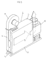
- the quadrangular type multi-tube once-through boiler unit according to the present invention comprises basically a boiler body 1 containing a water tube assembly (A), a burner means 3 equipped to one side of said boiler body 1, a burner duct 5 forming a premixed gas feed path 5a to said burner means 3 for feeding premixed gas to said burner means 3, a blower 4 equipped at one end or said burner duct 5 and an exhaust gas discharging means 6 equipped to the other side of said boiler body 1.
- Said boiler body 1 is constituted by a boiler casing 2 and a water tube assembly (A).
- Said boiler casing 2 constitutes a flat rectangular casing by a pair of opposing relatively wide end walls (W), (W) and the first S2, S4 and second S1, S3 pairs of opposing relatively narrow side walls.
- each constituting members including said burner means 3, said blower 4, said burner duct 5 and said exhaust gas discharging means 6 are designed to be positioned outside of the pair of first side walls S2, S4 and the pair of second side walls S1, S3 in said boiler body 1 and inside of the region divided by each extended surfaces of said pair of opposing end walls (W), (W).
- Said boiler body 1 provides a path forming means (P.M) for allowing substantially linear passage of the combustion gas from the side of said burner means 3 to the side of said exhaust gas discharging means 6 in said boiler body 1 and forms a combustion gas path (G.P) by said path forming means (P.M).
- P.M path forming means
- the water tube assembly (A) is composed of a plurality of vertically extending substantially parallel water tubes 10.
- Such assembly (A) is composed of vertically extending quadrangular construction, with combustion gases flowing crosswise of said group of water tubes.
- the water tubes 10 disposed on opposite outer sides are connected together by partition members 11, forming water tube walls 12 which are substantially parallel and positioned on opposite sides of the water tube assembly (A).
- the intermediate water tubes 10 between the water tube walls 12, 12 on opposite sides are arranged in a number of rows spaced lengthwise (longitudinally) of the water tube walls, each row consisting of two tubes disposed widthwise of the water tube assembly.
- These water tube rows 11, 12, 13 and so on and the water tubes 10 forming the water tube walls 12 differ in pitch from each other and arranged in zigzag.
- the clearance between adjacent water tubes 10 is nearly equal to or less than the diameter (d) of the water tubes 10. More particularly, the clearance between adjacent water tubes 10 in each of the water tube rows 11, 12, 13 and so on, and the clearance between a water tube 10 in one of two adjacent water tube rows and an adjacent water tube 10 in the other water tube row, and the clearance between a water tube 10 in each of the water tube walls 12 on the opposite sides and a water tube 10 in each of the water tube rows 11, 12, 13 and so on are nearly equal to or less than the diameter (d) of the water tubes 10. In addition, these clearances may be equal to or different from each other provided that the aforesaid condition is met.
- water tubes 10 are connected together at their upper and lower ends by upper and lower headers 15 and 16, respectively, thereby forming a narrow, substantially rectangular water tube assembly (A).
- a burner 3 suitable for this embodiment is a premixing type burner, such as a surface combustion burner, positioned at one longitudinal end of the water tube assembly (A).
- the clearance between this combustion burner 3 and the first water tube row 11 positioned close thereto is nearly equal to or less than a predetermined distance which is 3 times as large as the diameter (d) of the water tubes 10.
- the water tube in each of the water tube walls which is closest to the combustion burner 3 is positioned on the basis of said distance.
- the blower 4 is of the centrifugal type, disposed above the lateral wall portion S1.
- the delivery port 4a of this type of blower 4 is directed downward and disposed on the side of the boiler body 1 where the combustion burner 3 is installed, said delivery port 4a being connected to said combustion burner 3 by the burner duct 5 disposed on the wall portion S2.
- the burner duct 5 has a width which is nearly equal to or less than the width of water tube assembly (A) and is in the form of a quadrangular pillar, as shown, with a gas feed nozzle (not shown) disposed somewhere in said pillar, so that premixed gas flows from the opening in the outlet side to the burner 3.
- the exhaust gas discharging means 6 comprising economizer
- said economizer comprises a substantially L-shaped economizer body 21 and horizontally extending finned heat transfer tubes 20 disposed therein in lattice form.
- the opposite ends of these finned heat transfer tubes 20 extend through the lateral surfaces of the economizer body 21 and open.
- the four openings on one uppermost row are kept communicating with each other by headers 22a and 22b, respectively, disposed on the lateral surfaces of the economizer body 21, while the eight tubes in the two middle rows are kept communicating with each other by a similar header 22c.
- the exhaust gas discharging means 6 of this arrangement is disposed on the side opposed to the combustion burner 3, with the water tube assembly (A) interposed therebetween, in such a manner that the heat transfer tubes 20 extend crosswise of the water tubes 10 of the water tube assembly (A) of the boiler, the width of said economizer being substantially equal to the width of said water tube assembly (A).
- combustion air flows downward from the blower 4 via the burner duct 5 and on its way it is mixed with combustible gas from the gas feed nozzle to provide premixed gas, which is then fed to the combustion burner 3.
- the premixed gas flowing out of the combustion burner 3 is ignited in front of the combustion burner 3 to produce flames, traveling from left to right, as shown, through the clearances between the water tubes 10 of the water tube assembly (A), while completely burning.
- the combustion flames and combustion gases transfer heat to the water tubes 10.
- the flames from the combustion burner 3 extend long in the direction of the length of the water tube assembly as they travel through the clearances between the water tubes in the water tube rows 11, 12, 13 and so on; thus, burning reaction takes place also in these clearances.
- the flames from the combustion burner 3 come in contact first with the first water tube row 11, then with the second row 12, then with the third row 13, and so on, while they also come in contact with the water tube walls for successive heat transfer; thus, the flame temperature can be decreased to, e.g., 1200 °C -1300°C and hence the formation of thermal NO x can be suppressed.
- combustion flames swirl in the clearances between the water tubes 10 because of the presence of the water tubes 10, flame stability is improved and complete combustion is ensured as unburnt gas is rapidly drawn into the flame flow; particularly, CO is oxidized into CO2.
- combustion gases resulting from burning reaction, pass longitudinally of the water tube assembly (A) while coming in contact with the water tube rows and water tube walls and are kept within a relatively low temperature range. This also suppresses thermal dissociation of CO2 into CO.
- the channels for combustion air and combustion gases are formed in the space of a rectangular parallelepiped of predetermined width.
- the width of the entire boiler can be decreased to a value which allows formation of the channels; thus, the boiler width can be greatly decreased as compared with multi-tube once-through boilers having a conventional combustion chamber.
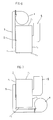
- the disposition and configurations of the blower 4 and burner duct 5 are not limited to the embodiment described above, but they may be changed as shown in Figs. 6 through 8.
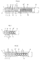
- the water tube assembly is not limited to one having the construction described above, but they may have a construction as shown in Figs. 9 through 12.
- the water tube assembly shown in Fig. 9 is a modification of the one shown in Fig. 2.
- two or more groups of water tubes different in heat transfer surface area are arranged in the order of increasing heat transfer surface area as seen from combustion gas upstream side to downstream side.
- a group of smooth water tubes 10, a group of laterally-finned water tubes 10' and a group of aerofinned water tubes 10'' are arranged in the order mentioned as seen from combustion gas upstream side to downstream side.
- the water tube walls 12 extend substantially to the middle of the water tube assembly, and the downstream side is narrowed. Between the water tube walls 12, water tubes 10 in the form of straight tubes are disposed in series, while in the region downstream or said water tube walls 12, two rows of aerofinned water tubes 10'' are disposed between heat insulating walls 18.
- Fig. 11 the water tube rows 11, 12 and 13, each consisting of two water tubes 10, are disposed immediately in front of the combustion burner 3, said water tube row 13 being followed by three aerofinned water tubes 10'' in a row, and partition walls 19 are disposed on opposite sides of said aerofinned water tubes 10''.
- the positional relation of the water tubes 10 and 10'' and combustion burner 3 is the same as described above.
- Fig. 12 the number of water tube rows is 7 and the number of aerofinned water tubes is 6.
- the quadrangular type multi-tube once-through boiler of the present invention develops its merits to a greater extent when applied to examples (package type) shown in Fig. 13 and 14.
- (X) denotes a boiler unit; (Y) denotes control box; 30 denotes a cabinet structure; 32 denotes front sealing panels; 33 denotes lateral sealing panes.
- the boiler unit (X) comprises a single boiler body 42 covered with a casing 41 and placed on a bed 40 and ancillary parts, such as a burner blower 43 and an economizer 44, attached to said body or bed 40.
- the cabinet structure 30, in the embodiment shown in Fig. 13, comprises a required number or a plurality of substantially vertically and horizontally extending connecting members 47a and 47b, thereby defining three receiving compartments 49.
- the members defining these receiving compartments are adapted to be separated and connected so as to make it possible to increase or decrease the number of receiving partitions 49.
- rails and rollers can be installed on the connecting members 47b' which form the bottom of a frame 47.
- the connecting members 47b' which form the bottom of a frame 47.
- the air feed path from the blower to the boiler body and the exhaust gas path from the boiler body passing through the flue can be formed substantially on the same plane along the flowing path of combustion gas in the boiler body and the flowing path of the combustion air-combustion gas can be set in a cubic volume of a specified width to largely decrease the width and space of the whole boiler.
- the quadrangular type multi-tube once-through boiler unit according to the present invention has a decreased width as mentioned above and each accessaries are arranged to the longitudinal or upper direction of the boiler body and thus the total shape is flat vertical form. This merit can be highly exerted in the multi-boiler system widely used recently.
- the boiler body of the quadrangular type multi-tube once-through boiler unit can control the temperatures of combustion flame in the space between the water tubes and combustion gas within a relatively low range by each water tubes and hence special conventional equipments and structures for preventing hazardous exhaust gas are not required to make the structure simple and to lower the cost.
- the quadrangular type multi-tube once-through boiler unit according to the present invention by equipping a economizer in which the heat transfer tubes are arranged crosswise to the water tube direction of said boiler body on the part over the side wall portion facing to the burner duct, increase in the width is substantially nothing and the installing area is not so highly increased by equipping the economizer in such a way as seen in the conventional boiler system.
- a desired number of boiler units can be equipped, if required, in the minimum floor space regularly.
- the plurality of boiler units contained in the cabinet structure can be removed by each boiler unit for repair, inspection and renewal. Further, by providing control boxes in the front of each boiler units, laborsaving operation can be performed and it can be said to act very effectively in that respect.
Landscapes
- Engineering & Computer Science (AREA)
- Physics & Mathematics (AREA)
- Thermal Sciences (AREA)
- Mechanical Engineering (AREA)
- General Engineering & Computer Science (AREA)
- Chemical & Material Sciences (AREA)
- Combustion & Propulsion (AREA)
- Combustion Of Fluid Fuel (AREA)
- Air Supply (AREA)
- Incineration Of Waste (AREA)
Abstract
Claims (6)
- Une chaudière multitubulaire de type quadruple à passage forcé unique comprenant une enceinte de chaudière, un assemblage de tubes d'eau, arrangés dans l'enceinte et comprenant plusieurs tubes d'eau verticaux disposés parallèlement les uns par rapport aux autres, l'assemblage ayant, en fait une forme quadrangulaire, les tubes d'eau étant branchés à leur extrémité supérieure à un socle supérieur (15) et à leur extrémité inférieure à un socle inférieur (16), un moyen de brûleur (3) placé à une extrémité de la longueur dudit assemblage de tubes d'eau, un moyen d'évacuation des gaz d'échappement (6) placé à l'autre extrémité de la longueur dudit assemblage de tubes d'eau, une canalisation de brûleur (5) branchée pour permettre la fourniture en gaz dudit brûleur, un ventilateur branché à une extrémité de ladite canalisation de brûleur, caractérisée par le fait que ledit assemblage des tubes d'eau (A) comprend deux rangées de tubes d'eau, chacune desdites rangées partant d'un endroit adjacent au moyen de brûleur et allant au moins en partie vers le moyen d'évacuation des gaz d'échappement, les tubes d'eau adjacents (10) dans chacune desdites deux rangées de tubes d'eau étant connectés entre eux par des membres de séparation (11) afin de former la première et la deuxième parois des tubes d'eau (12), lesdites première et deuxième parois des tubes d'eau, ledit socle supérieur (15) et ledit socle inférieur formant une voie des gaz de combustion permettant le passage linéaire en fait des gaz de combustion dans une direction d'orientation transversale par rapport à l'assemblage des tubes d'eau depuis ledit moyen de brûleur jusqu'au dit moyen d'évacuation des gaz d'échappement, et ledit assemblage des tubes d'eau comprenant également une rangée supplémentaire ou plusieurs de tubes d'eau verticaux (10) placés entre lesdites première et deuxième parois des tubes d'eau partant d'un endroit adjacent audit moyen de brûleur et allant vers ledit moyen d'évacuation des gaz d'échappement.
- Une chaudière multitubulaire de type quadrangulaire àpassage forcé unique selon la revendication 1, dans laquelle chacune desdites rangées supplémentaires de tubes d'eau comprend plusieurs groupes de tubes d'eau (10, 10', 10'') qui ont une densité de surface thermoconductrice qui s'accroît progressivement dans la direction allant depuis le moyen de brûleur (3) vers le moyen d'évacuation des gaz d'échappement (6).
- Une chaudière multitubulaire de type quadrangulaire à passage forcé unique selon la revendication 1, dans laquelle la distance entre les tubes d'eau adjacents (10) dans ledit assemblage des tubes d'eau est en fait égale ou inférieure au diamètre (d) des tubes d'eau.
- Une chaudière multitubulaire de type quadrangulaire à passage forcé unique selon la revendication 1, dans laquelle lesdits tubes d'eau (10) de ladite rangée supplémentaire ou desdites rangées supplémentaires de lignes de tubes d'eau sont échelonnés par rapport aux dits tubes d'eau formant lesdites parois des tubes d'eau (12).
- Une chaudière multitubulaire de type quadrangulaire à passage forcé unique selon la revendication 1, dans laquelle la distance entre ledit moyen de brûleur (3) et le tube ou les tubes d'eau de ladite rangée supplémentaire ou desdites rangées supplémentaires la ou les plus rapprochée(s) desdites lignes du moyen de brûleur est en fait égale ou inférieure à trois fois le diamètre (d) desdits tubes d'eau.
- Une chaudière multitubulaire de type quadrangulaire à passage forcé unique selon la revendication 1, dans laquelle ledit moyen de brûleur (3) est un brûleur du type mélange au préalable.
Applications Claiming Priority (7)
| Application Number | Priority Date | Filing Date | Title |
|---|---|---|---|
| JP1988166661U JPH0285201U (fr) | 1988-12-22 | 1988-12-22 | |
| JP166661/88U | 1988-12-22 | ||
| JP167485/88U | 1988-12-23 | ||
| JP1988167485U JPH0619922Y2 (ja) | 1988-12-23 | 1988-12-23 | 連結組立式ボイラー |
| JP1989017457U JPH02109103U (fr) | 1989-02-16 | 1989-02-16 | |
| JP117457/89U | 1989-02-16 | ||
| PCT/JP1989/001279 WO1990007084A1 (fr) | 1988-12-22 | 1989-12-20 | Chaudiere carree a conduites multiples et a passage unique |
Publications (3)
| Publication Number | Publication Date |
|---|---|
| EP0450072A1 EP0450072A1 (fr) | 1991-10-09 |
| EP0450072A4 EP0450072A4 (en) | 1992-12-02 |
| EP0450072B1 true EP0450072B1 (fr) | 1995-04-26 |
Family
ID=27281839
Family Applications (1)
| Application Number | Title | Priority Date | Filing Date |
|---|---|---|---|
| EP90900364A Expired - Lifetime EP0450072B1 (fr) | 1988-12-22 | 1989-12-20 | Chaudiere carree a conduites multiples et a passage unique |
Country Status (7)
| Country | Link |
|---|---|
| US (1) | US5199384A (fr) |
| EP (1) | EP0450072B1 (fr) |
| KR (1) | KR950004497B1 (fr) |
| AU (1) | AU628463B2 (fr) |
| CA (1) | CA2006576C (fr) |
| DE (1) | DE68922403T2 (fr) |
| WO (1) | WO1990007084A1 (fr) |
Families Citing this family (24)
| Publication number | Priority date | Publication date | Assignee | Title |
|---|---|---|---|---|
| JP3221582B2 (ja) * | 1992-09-09 | 2001-10-22 | 株式会社三浦研究所 | 低NOx、及び低CO燃焼装置 |
| DE4230507A1 (de) * | 1992-09-11 | 1994-03-17 | Gisela Yotis | Dampfkessel |
| DE19651936C2 (de) * | 1996-12-14 | 2000-08-31 | Nem Bv | Durchlaufdampferzeuger mit einem Gaszug zum Anschließen an eine Heißgas abgebende Vorrichtung |
| CA2211983C (fr) * | 1997-02-28 | 2006-03-14 | Miura Co., Ltd. | Chaudiere a tubes d'eau |
| JPH11108308A (ja) * | 1997-09-30 | 1999-04-23 | Miura Co Ltd | 水管ボイラおよびバーナ |
| JPH11132404A (ja) * | 1997-10-31 | 1999-05-21 | Miura Co Ltd | 水管ボイラ |
| ES2170588T3 (es) | 1998-06-10 | 2002-08-01 | Siemens Ag | Generador de vapor calentado con combustible fosil. |
| DE19825800A1 (de) * | 1998-06-10 | 1999-12-16 | Siemens Ag | Fossilbeheizter Dampferzeuger |
| DE19858780C2 (de) * | 1998-12-18 | 2001-07-05 | Siemens Ag | Fossilbeheizter Durchlaufdampferzeuger |
| DE19901621A1 (de) * | 1999-01-18 | 2000-07-27 | Siemens Ag | Fossilbeheizter Dampferzeuger |
| JP2000314502A (ja) | 1999-04-30 | 2000-11-14 | Miura Co Ltd | 水管ボイラ |
| JP2000314501A (ja) | 1999-04-30 | 2000-11-14 | Miura Co Ltd | 水管ボイラ |
| KR100354814B1 (ko) * | 1999-10-25 | 2002-09-30 | 사단법인 고등기술연구원 연구조합 | 비산재 부착 방지형 연관 보일러 |
| US6383461B1 (en) | 1999-10-26 | 2002-05-07 | John Zink Company, Llc | Fuel dilution methods and apparatus for NOx reduction |
| GB0011224D0 (en) * | 2000-05-10 | 2000-06-28 | Eaton Williams Group Ltd | A gaas-fired humidifier |
| JP2004125378A (ja) * | 2002-07-15 | 2004-04-22 | Miura Co Ltd | 低NOx燃焼方法とその装置 |
| EP1398564A1 (fr) | 2002-09-10 | 2004-03-17 | Siemens Aktiengesellschaft | Procédé pour faire fonctionner un générateur de vapeur à construcion horizontale, et générateur de vapeur pour mettre en oeuvre ledit procédé |
| EP1398565A1 (fr) | 2002-09-10 | 2004-03-17 | Siemens Aktiengesellschaft | Générateur de vapeur à construction horizontale |
| TW200636192A (en) * | 2005-03-22 | 2006-10-16 | Miura Kogyo Kk | Damper position adjusting device and combustion apparatus having such damper adjusting device |
| TWI372844B (en) * | 2005-07-04 | 2012-09-21 | Miura Kogyo Kk | Boiler |
| JP5151373B2 (ja) * | 2006-11-30 | 2013-02-27 | 三浦工業株式会社 | ボイラ |
| JP2009174766A (ja) * | 2008-01-23 | 2009-08-06 | Miura Co Ltd | 燃焼装置 |
| JP4419156B1 (ja) * | 2009-05-15 | 2010-02-24 | 三浦工業株式会社 | ボイラ |
| RU209298U1 (ru) * | 2021-10-18 | 2022-03-15 | Анатолий Иванович Изосимов | Котел водотрубный |
Family Cites Families (15)
| Publication number | Priority date | Publication date | Assignee | Title |
|---|---|---|---|---|
| JPS3511402Y1 (fr) * | 1958-07-23 | 1960-05-26 | ||
| JPS49601A (fr) * | 1972-04-19 | 1974-01-07 | ||
| JPS5097703A (fr) * | 1974-01-08 | 1975-08-04 | ||
| FR2499223B1 (fr) * | 1979-11-23 | 1985-06-28 | Landreau Andre | Chaudiere, notamment pour installation de chauffage |
| JPS56136902U (fr) * | 1980-03-14 | 1981-10-16 | ||
| JPS56136904U (fr) * | 1980-03-14 | 1981-10-16 | ||
| FR2524971A1 (fr) * | 1982-04-08 | 1983-10-14 | Deleage Philippe | Generateur de chauffe modulaire |
| JPS58203371A (ja) * | 1982-05-21 | 1983-11-26 | 株式会社日立製作所 | 蒸気発生装置 |
| FR2545585B1 (fr) * | 1983-05-05 | 1989-04-21 | Laurent Francois | Perfectionnements a des generateurs de chaleur fonctionnant au gaz et susceptibles d'etre raccordes a une aspiration controlee |
| JPS6169601U (fr) * | 1984-10-05 | 1986-05-13 | ||
| JPS6169602U (fr) * | 1984-10-05 | 1986-05-13 | ||
| JPS61165302U (fr) * | 1985-03-29 | 1986-10-14 | ||
| WO1987003068A1 (fr) * | 1985-11-15 | 1987-05-21 | Joh. Vaillant Gmbh U. Co | Bruleur a gaz avec tuyaux de refroidissement des flammes du bruleur |
| US4685426A (en) * | 1986-05-05 | 1987-08-11 | The Babcock & Wilcox Company | Modular exhaust gas steam generator with common boiler casing |
| US5040470A (en) * | 1988-03-25 | 1991-08-20 | Shell Western E&P Inc. | Steam generating system with NOx reduction |
-
1989
- 1989-12-20 US US07/720,832 patent/US5199384A/en not_active Expired - Lifetime
- 1989-12-20 DE DE68922403T patent/DE68922403T2/de not_active Expired - Fee Related
- 1989-12-20 WO PCT/JP1989/001279 patent/WO1990007084A1/fr not_active Ceased
- 1989-12-20 AU AU48051/90A patent/AU628463B2/en not_active Ceased
- 1989-12-20 EP EP90900364A patent/EP0450072B1/fr not_active Expired - Lifetime
- 1989-12-22 CA CA002006576A patent/CA2006576C/fr not_active Expired - Lifetime
-
1990
- 1990-12-20 KR KR1019900701751A patent/KR950004497B1/ko not_active Expired - Lifetime
Also Published As
| Publication number | Publication date |
|---|---|
| EP0450072A4 (en) | 1992-12-02 |
| KR950004497B1 (ko) | 1995-05-01 |
| US5199384A (en) | 1993-04-06 |
| WO1990007084A1 (fr) | 1990-06-28 |
| EP0450072A1 (fr) | 1991-10-09 |
| CA2006576C (fr) | 1998-08-25 |
| KR910700433A (ko) | 1991-03-15 |
| AU4805190A (en) | 1990-07-10 |
| DE68922403D1 (de) | 1995-06-01 |
| CA2006576A1 (fr) | 1990-06-22 |
| DE68922403T2 (de) | 1995-10-05 |
| AU628463B2 (en) | 1992-09-17 |
Similar Documents
| Publication | Publication Date | Title |
|---|---|---|
| EP0450072B1 (fr) | Chaudiere carree a conduites multiples et a passage unique | |
| US5273001A (en) | Quadrangular type multi-tube once-through boiler | |
| JP3221582B2 (ja) | 低NOx、及び低CO燃焼装置 | |
| EP2361148B1 (fr) | Chaudière à lit fluidisé circulant | |
| US4355602A (en) | Boiler | |
| EP0981017B1 (fr) | Chaudière | |
| KR20110079636A (ko) | 복사 튜브 버너용 복열 장치 | |
| US4612879A (en) | Hot water heater and steam generator | |
| US4182276A (en) | Economizer for smoke tube boilers for high pressure steam and hot water | |
| TW393553B (en) | Low Nox integrated boiler-burner apparatus | |
| EP2884169B1 (fr) | Appareil à lit fluidisé | |
| KR19990071571A (ko) | 복수의 노 출구를 갖춘 순환유동상 반응로 | |
| CN213542429U (zh) | 一种燃气蒸汽锅炉 | |
| EP2884162A1 (fr) | Échangeur de chaleur à lit fluidisé | |
| EP0042215B1 (fr) | Chaudière | |
| EP2884170A1 (fr) | Appareil à lit fluidisé | |
| EP2884172A1 (fr) | Siphon à lit fluidisé | |
| US2149007A (en) | Heat exchanger | |
| US4627387A (en) | Fluidized-bed apparatus with a heat exchanger and an additional-air blowing network | |
| JP2673306B2 (ja) | 角型多管式貫流ボイラ | |
| JP2850052B2 (ja) | Uf型ボイラ | |
| US4342286A (en) | Integral economizer steam generator | |
| JP3368887B2 (ja) | 低NOxおよび低CO燃焼方法 | |
| US2292682A (en) | Heating of fluid | |
| JPH04208301A (ja) | 多管式貫流ボイラ |
Legal Events
| Date | Code | Title | Description |
|---|---|---|---|
| PUAI | Public reference made under article 153(3) epc to a published international application that has entered the european phase |
Free format text: ORIGINAL CODE: 0009012 |
|
| 17P | Request for examination filed |
Effective date: 19910618 |
|
| AK | Designated contracting states |
Kind code of ref document: A1 Designated state(s): AT BE CH DE ES FR GB IT LI LU NL |
|
| RBV | Designated contracting states (corrected) |
Designated state(s): BE DE FR GB NL |
|
| A4 | Supplementary search report drawn up and despatched |
Effective date: 19921014 |
|
| AK | Designated contracting states |
Kind code of ref document: A4 Designated state(s): AT BE CH DE ES FR GB IT LI LU NL |
|
| 17Q | First examination report despatched |
Effective date: 19931124 |
|
| GRAA | (expected) grant |
Free format text: ORIGINAL CODE: 0009210 |
|
| AK | Designated contracting states |
Kind code of ref document: B1 Designated state(s): BE DE FR GB NL |
|
| REF | Corresponds to: |
Ref document number: 68922403 Country of ref document: DE Date of ref document: 19950601 |
|
| ET | Fr: translation filed | ||
| PG25 | Lapsed in a contracting state [announced via postgrant information from national office to epo] |
Ref country code: GB Effective date: 19951220 |
|
| PLBE | No opposition filed within time limit |
Free format text: ORIGINAL CODE: 0009261 |
|
| STAA | Information on the status of an ep patent application or granted ep patent |
Free format text: STATUS: NO OPPOSITION FILED WITHIN TIME LIMIT |
|
| 26N | No opposition filed | ||
| GBPC | Gb: european patent ceased through non-payment of renewal fee |
Effective date: 19951220 |
|
| PGFP | Annual fee paid to national office [announced via postgrant information from national office to epo] |
Ref country code: NL Payment date: 20011120 Year of fee payment: 13 |
|
| PGFP | Annual fee paid to national office [announced via postgrant information from national office to epo] |
Ref country code: DE Payment date: 20011208 Year of fee payment: 13 |
|
| PGFP | Annual fee paid to national office [announced via postgrant information from national office to epo] |
Ref country code: FR Payment date: 20011211 Year of fee payment: 13 |
|
| PGFP | Annual fee paid to national office [announced via postgrant information from national office to epo] |
Ref country code: BE Payment date: 20011220 Year of fee payment: 13 |
|
| PG25 | Lapsed in a contracting state [announced via postgrant information from national office to epo] |
Ref country code: BE Free format text: LAPSE BECAUSE OF NON-PAYMENT OF DUE FEES Effective date: 20021231 |
|
| BERE | Be: lapsed |
Owner name: *MIURA CO. LTD Effective date: 20021231 |
|
| PG25 | Lapsed in a contracting state [announced via postgrant information from national office to epo] |
Ref country code: NL Free format text: LAPSE BECAUSE OF NON-PAYMENT OF DUE FEES Effective date: 20030701 Ref country code: DE Free format text: LAPSE BECAUSE OF NON-PAYMENT OF DUE FEES Effective date: 20030701 |
|
| NLV4 | Nl: lapsed or anulled due to non-payment of the annual fee |
Effective date: 20030701 |
|
| PG25 | Lapsed in a contracting state [announced via postgrant information from national office to epo] |
Ref country code: FR Free format text: LAPSE BECAUSE OF NON-PAYMENT OF DUE FEES Effective date: 20030901 |
|
| REG | Reference to a national code |
Ref country code: FR Ref legal event code: ST |