EP0450085A1 - Dispositif de bobinage de fil du type tourelle - Google Patents
Dispositif de bobinage de fil du type tourelle Download PDFInfo
- Publication number
- EP0450085A1 EP0450085A1 EP90914421A EP90914421A EP0450085A1 EP 0450085 A1 EP0450085 A1 EP 0450085A1 EP 90914421 A EP90914421 A EP 90914421A EP 90914421 A EP90914421 A EP 90914421A EP 0450085 A1 EP0450085 A1 EP 0450085A1
- Authority
- EP
- European Patent Office
- Prior art keywords
- yarn
- bobbin
- traverse
- winder
- winding
- Prior art date
- Legal status (The legal status is an assumption and is not a legal conclusion. Google has not performed a legal analysis and makes no representation as to the accuracy of the status listed.)
- Granted
Links
- 238000004804 winding Methods 0.000 title claims abstract description 40
- 230000007246 mechanism Effects 0.000 claims abstract description 53
- 230000033001 locomotion Effects 0.000 claims description 74
- 238000006073 displacement reaction Methods 0.000 claims description 5
- 230000005540 biological transmission Effects 0.000 claims description 3
- 230000000452 restraining effect Effects 0.000 claims description 2
- 238000005520 cutting process Methods 0.000 description 6
- 230000006835 compression Effects 0.000 description 3
- 238000007906 compression Methods 0.000 description 3
- 238000000034 method Methods 0.000 description 3
- 230000008569 process Effects 0.000 description 3
- 238000001514 detection method Methods 0.000 description 2
- 230000006872 improvement Effects 0.000 description 2
- 229920000049 Carbon (fiber) Polymers 0.000 description 1
- 230000001133 acceleration Effects 0.000 description 1
- 230000009471 action Effects 0.000 description 1
- 230000008901 benefit Effects 0.000 description 1
- 230000015572 biosynthetic process Effects 0.000 description 1
- 229910052799 carbon Inorganic materials 0.000 description 1
- 239000004917 carbon fiber Substances 0.000 description 1
- 239000000919 ceramic Substances 0.000 description 1
- 230000008859 change Effects 0.000 description 1
- 239000000835 fiber Substances 0.000 description 1
- 238000012423 maintenance Methods 0.000 description 1
- 238000004519 manufacturing process Methods 0.000 description 1
- VNWKTOKETHGBQD-UHFFFAOYSA-N methane Chemical compound C VNWKTOKETHGBQD-UHFFFAOYSA-N 0.000 description 1
- 230000004048 modification Effects 0.000 description 1
- 238000012986 modification Methods 0.000 description 1
- 230000002093 peripheral effect Effects 0.000 description 1
- 238000004513 sizing Methods 0.000 description 1
- 230000007704 transition Effects 0.000 description 1
Images


Classifications
-
- B—PERFORMING OPERATIONS; TRANSPORTING
- B65—CONVEYING; PACKING; STORING; HANDLING THIN OR FILAMENTARY MATERIAL
- B65H—HANDLING THIN OR FILAMENTARY MATERIAL, e.g. SHEETS, WEBS, CABLES
- B65H54/00—Winding, coiling, or depositing filamentary material
- B65H54/02—Winding and traversing material on to reels, bobbins, tubes, or like package cores or formers
- B65H54/28—Traversing devices; Package-shaping arrangements
- B65H54/2893—Superposed traversing, i.e. traversing or other movement superposed on a traversing movement
-
- B—PERFORMING OPERATIONS; TRANSPORTING
- B65—CONVEYING; PACKING; STORING; HANDLING THIN OR FILAMENTARY MATERIAL
- B65H—HANDLING THIN OR FILAMENTARY MATERIAL, e.g. SHEETS, WEBS, CABLES
- B65H54/00—Winding, coiling, or depositing filamentary material
- B65H54/02—Winding and traversing material on to reels, bobbins, tubes, or like package cores or formers
- B65H54/40—Arrangements for rotating packages
- B65H54/52—Drive contact pressure control, e.g. pressing arrangements
-
- B—PERFORMING OPERATIONS; TRANSPORTING
- B65—CONVEYING; PACKING; STORING; HANDLING THIN OR FILAMENTARY MATERIAL
- B65H—HANDLING THIN OR FILAMENTARY MATERIAL, e.g. SHEETS, WEBS, CABLES
- B65H54/00—Winding, coiling, or depositing filamentary material
- B65H54/70—Other constructional features of yarn-winding machines
- B65H54/74—Driving arrangements
-
- B—PERFORMING OPERATIONS; TRANSPORTING
- B65—CONVEYING; PACKING; STORING; HANDLING THIN OR FILAMENTARY MATERIAL
- B65H—HANDLING THIN OR FILAMENTARY MATERIAL, e.g. SHEETS, WEBS, CABLES
- B65H67/00—Replacing or removing cores, receptacles, or completed packages at paying-out, winding, or depositing stations
- B65H67/04—Arrangements for removing completed take-up packages and or replacing by cores, formers, or empty receptacles at winding or depositing stations; Transferring material between adjacent full and empty take-up elements
- B65H67/044—Continuous winding apparatus for winding on two or more winding heads in succession
- B65H67/048—Continuous winding apparatus for winding on two or more winding heads in succession having winding heads arranged on rotary capstan head
-
- B—PERFORMING OPERATIONS; TRANSPORTING
- B65—CONVEYING; PACKING; STORING; HANDLING THIN OR FILAMENTARY MATERIAL
- B65H—HANDLING THIN OR FILAMENTARY MATERIAL, e.g. SHEETS, WEBS, CABLES
- B65H2515/00—Physical entities not provided for in groups B65H2511/00 or B65H2513/00
- B65H2515/30—Forces; Stresses
- B65H2515/34—Pressure, e.g. fluid pressure
-
- B—PERFORMING OPERATIONS; TRANSPORTING
- B65—CONVEYING; PACKING; STORING; HANDLING THIN OR FILAMENTARY MATERIAL
- B65H—HANDLING THIN OR FILAMENTARY MATERIAL, e.g. SHEETS, WEBS, CABLES
- B65H2701/00—Handled material; Storage means
- B65H2701/30—Handled filamentary material
- B65H2701/31—Textiles threads or artificial strands of filaments
Definitions
- the present invention relates to a turret type yarn winder, in which a pair of chucks for holding bobbins are arranged on a turret disc coaxial by and symmetrical to each other, and a full bobbin and an empty bobbin held on the respective chucks are alternately exchanged by the rotation of the disc so that the winding operation can be carried out without interruption.
- a winder of the above type in which a yarn is taken up onto the bobbin while being traversed by a yarn traverse mechanism, during which the turret disc is rotated so that one chuck holding a working bobbin on which the yarn is being wound is gradually distanced from the traverse mechanism secured in a fixed position.
- a yarn now being taken up is removed from a traverse guide to be transferred out of the normal traverse range of the yarn traverse mechanism with the aid of an exclusive guide means, is wound on an empty bobbin while the yarn is held by a yarn holding means secured, for example, on a base portion of a bobbin chuck, and then is severed from the full bobbin.
- a desired rotational speed of a motor which speed is controlled to correspond to a smaller diameter of a bobbin on which a yarn is freshly wound
- the yarn is liable to be slackened due to the lower rotational speed of a bobbin chuck holding the empty bobbin, whereby a smooth yarn transfer and winding operation are hindered.
- a plurality of dancer rolls are provided on a yarn feeding path to absorb yarn slack caused by the disparity between a yarn feeding speed and a yarn winding speed on a bobbin (see Japanese Examined Patent Publication No. 48-31178).
- a winder using an exclusive guide for a yarn transfer provided other than a yarn traverse guide, has drawbacks in that it must have a complicated mechanism for driving the exclusive guide, the motion of which becomes inaccurate because of a repeated yarn transfer and often breaks down, which increases the man/hour required for the maintenance thereof.
- the mechanism for absorbing a yarn slack by a series of dancer rolls at the beginning of a yarn transfer causes the total size thereof to be enlarged, and it is difficult to obtain the predetermined removal of yarn slack due to the rotational resistance of the dancer roll itself, as well as the yarn friction.
- a primary object of the present invention is to eliminate the above-mentioned drawbacks of the prior arts, and to provide a mechanism capable of transferring a yarn without the provision of an exclusive yarn transferring guide, while utilizing the conventional yarn traversing device used for the normal yarn winding.
- a second object of the present invention is to provide a clutch mechanism for rotating the respective bobbin chucks so that the yarn transfer from a full bobbin and an empty bobbin can be smoothly carried out by modifying a torque transmitted to the bobbin chuck, without using a complicated and expensive control means, by the utilization of an orbital motion of a bobbin chuck which begins from the starting position via a full bobbin position where a full bobbin is removed and an empty bobbin is supplied, and resumes again the starting position.
- the primary object of the present invention is attained by a turret type yarn winder in which a pair of bobbin chucks are arranged on a turret disc symmetrically with each other relative to a center of the turret disc and a continuous yarn winding operation is carried out by repeating the steps of: taking up a yarn on a bobbin carried by one of the bobbin chucks while subjecting the yarn to a traverse motion by a traverse guide; displacing an empty bobbin carried by the other bobbin chuck to a winding-start position through an orbital motion of the turret disc; and transferring the yarn on the full bobbin to a yarn end holding device provided at a base end portion of the empty bobbin, characterized in that the winder comprises a first detecting means for detecting the arrival of a bobbin chuck carrying an empty bobbin at a yarn-transfer position just before a winding-start position during the course of the orbital motion and outputting a
- the yarn end holding device comprises an annular clamp member engageable with and disengageable from a friction member provided on the base end surface of the bobbin chuck, and means for displacing the annular clamp member away from the bobbin end surface at the predetermined phase of the orbital motion of the bobbin chuck.
- the annular member is provided with a plurality of hooks on the periphery thereof on the side in contact with the friction member.
- the yarn traverse cam shifting mechanism is a pneumatic cylinder but the cam is slidably mounted on a shaft.
- the engagement and disengagement between the annular member and the friction member are carried out in synchronism with the shifting of the yarn traverse cam.
- the engagement and disengagement between the annular member and the friction member are carried out by a cam mechanism arranged along a path of the orbital motion of the bobbin chucks.
- a winder advantageously further comprises means for forming a bunch wind, which comprises a bunch lever provided with a hook portion for restraining a traverse motion of a yarn brought out of the normal traverse range by the shifting operation of the yarn traverse cam; said bunch lever being reversibly pivotable between an operative position and a waiting position and actuated synchronously with the shifting of the yarn traverse cam 4.
- the second object of the present invention is attained by a turret type yarn winder comprising a turret disc driven to rotate about a center thereof by a first motor, a pair of bobbin chucks rotatably secured on the turret disc at positions symmetrical with each other relative to the center of the turret disc, a pair of spindles for carrying the respective bobbin chucks, and a second motor for commonly driving the spindles; a continuous yarn winding operation being carried out by circulating a bobbin carried by one of the bobbin chucks along a path of orbital motion starting from a winding-start position through a full bobbin position, a doffing section, a yarn-transfer position, and coming back again to the winding-start position, while a full bobbin is being doffed from the bobbin chuck and an empty bobbin is being donned thereon in the doffing section, characterized in that, the winder further comprises a mechanical clutch mechanism
- the clutch mechanism is selectively switched to any one of three states of a full engagement in which a torque from the motor is fully transmitted to the spindle, a half engagement in which part of the torque is transmitted to the spindle, and a non-engagement in which no torque is transmitted to the spindle.
- the clutch mechanism of the spindle carrying a bobbin is maintained in the full engagement state in the course of the orbital motion between the winding-start position and the full bobbin position, in the half engagement state between the full bobbin position and the doffing-start position, and in the non-engagement state between the doffing-start position and the doffing-end position, then again returns the full engagement state thereafter.
- the orbital motion of the bobbin chuck is interrupted at the yarn-transfer position so that the yarn transfer operation is correctly carried out.
- the first motor is a stepping motor and the second motor is a torque motor or a speed-variable motor.
- the turret disc is driven along the path of the orbital motion by the intermittent rotation of the motor from the doffing-start position to the doffing-end position, then by the continuous rotation thereof from the doffing-end position to the yarn-transfer position, and then stops at the yarn-transfer position for a predetermined period, and by the continuous rotation to the winding-start position.
- a pair of bobbin chucks 1a, 1b are provided at diametrically symmetrical positions on a circle while held in rotation about their own axes, respectively.
- a bobbin 3a held thereon is first positioned at a winding-start position A and subjected to an orbital motion in the counterclockwise direction as the diameter thereof increases due to the yarn wound thereon; and reaches a full-bobbin position B when the bobbin has become full.
- a bobbin held thereon i.e., a fresh empty bobbin 3b just mounted in place of a full bobbin 3a while passing the doffing-start position D reaches a yarn-transfer position F via the doffing-end position E, and thereafter, runs on a path of the orbital motion while passing the winding-start position A, the full bobbin position B a yarn-transfer symmetrical position C, and the doffing-start position D.
- a yarn is continuously taken up without an interruption of yarn delivery by repeating the switching of both bobbin chucks.
- the doffing-start position D means a position where the doffing operation is possible on the bobbin chuck after it has passed this position
- the doffing-end position E means a position where the doffing operation should be completed by the time the bobbin chuck has reached this position. Therefore, the actual doffing operation can be carried out at any position included in doffing section defined between the doffing-start position D and the doffing-end position E.
- a pair of bobbin chucks 1a, 1b are rotationally arranged on a turret disc 2.
- One bobbin chuck 1a is positioned at the winding-start position A confronting a yarn traverse device 4 secured at a fixed position.
- a yarn Y is wound on the bobbin 3a held on the bobbin chuck 1a while traversed by a yarn traverse guide 5, as shown in Fig. 1.
- the turret disc 2 is rotatably accommodated in an aperture provided in a fixed machine frame 6 while held at the periphery thereof by rolls 7, and driven in the arrowed direction as shown in Fig. 1 by a stepping motor 9 through an intermesh between a driving gear 10 associated with the stepping motor 9 and a large wheel 8 fixedly secured on the rear part of bearing members 2a and a support member 2b of the disc 2.
- Spindles 11a, 11b of the respective bobbin chucks 1a, 1b support the bearing members 2a while passing there through and carry a pulley 12, respectively, at the free end thereof.
- a pulley 15 is fixedly mounted on a shaft 14 held on the support member 2b while passing through the center of the large wheel 8, and driven, together with pulleys 12, 12 secured at the ends of the respective spindle shafts, by a timing belt 13 via tension pulley 16.
- a pulley 17 secured at an other end of the shaft 14 and a pulley 19a of an intermediate shaft 18 are driven by a timing belt 21 via a tension pulley 20.
- An intermediate pulley 19b and a pulley 22 secured at an end of a traverse cam 4a of the yarn traverse device 4 is driven by a driving motor 23 via a tension pulley 24 and a timing belt 25.
- the respective spindles 11a, 11b of the bobbin chucks 1a, 1b and the traverse cam 4a are driven by the motor 23 while maintaining a predetermined relationship between the rotational speeds thereof.
- the motor 23 is either adapted to be speed-controlled automatically so that the take-up speed is kept constant in accordance with the displacement of dancer rollers due to the variation of a tension of yarn Y delivered continuously at a constant speed, or manufactured as a torque motor by which a substantially constant tension is ensured due to the principle thereof.
- the spindles 11a, 11b, and thus the bobbin chucks 1a, 1b are simultaneously subjected to the same directional orbital motion and rotated in the same direction on their own axes by the motor 23 through an associated mechanism.
- the yarn traverse device 4 is arranged behind the machine frame 6 and has a known yarn traverse cam 4a with a pair of grooves 4b across one another.
- a traverse guide 5 fixed on a rod 4d connected to a sliding guide 4c engaged with the grooves 4b is subjected to a traverse motion while confronting the bobbin chuck 1a occupying the winding-start position A shown in Fig. 1 due to a reciprocated motion of the rod 4d in the lengthwise direction along the machine frame 6.
- the bobbin 3a on the bobbin chuck 1a at the winding-start position A is rotated about its own axis while in contact with a pressure roller 27 and winds the yarn Y thereon.
- the pressure roller 27 is swung counterclockwise in Fig. 1 to cause a swingable member 26 to move to a position shown by a chain line, whereby the free end of the member 26 is distanced from a proximity switch 28 arranged in the vicinity thereof.
- This displacement is detected by the proximity switch 28 and the stepping motor 9 for the orbital motion of the turret disc 2 is started by the detected signal, whereby the turret disc 2 is subjected to the orbital motion in the counterclockwise direction.
- the stepping motor 9 is made to stop but the yarn winding operation continues at that position.
- the bobbin chuck 1a is intermittently subjected to a part of the orbital motion while continuing the yarn winding in accordance with the repletion of a start and stop of the stepping motor 9.
- a projection 29a on the turret disc 2 is in contact with a limit switch 30 on the machine frame 6.
- the stepping motor 9 is shifted to a continuous operation phase for bobbin-switching so that the turret disc 2 is continuously subjected to the orbital motion to cause an empty bobbin 3b carried on the other bobbin chuck 1b to be displaced to the yarn-transfer position F.
- another projection 31b on the turret disc 2 is in contact with another limit switch 32, whereby the stepping motor 9 stops so that the full bobbin 3a and the empty bobbin 3b temporarily rest at the positions C and F, respectively, whereby the yarn-transfer operation can be correctly carried out.
- the stepping motor 9 is restarted and the orbital motion continues to quickly bring the empty bobbin 3b to the winding-start position A and the full bobbin 3a to the doffing-start position D, respectively.
- the bobbin switching operation is completed. According to the repetition of the bobbin switching operations, the continuous yarn winding can be carried out without the interruption of the yarn delivery while alternately using the respective two bobbin chucks.
- a yarn holding device 38 is provided at the base end of the respective bobbin chucks 1a, 1b, by a slide ring 35 integral with an annular clamp member 33 having a plurality of hooks 34 at a periphery thereof, which ring 35 is rotatable together with the bobbin chuck and slidable in the axial direction by a bias of a spring 37 so that the side surface of the respective hook 34 is always pressed onto a friction member 36 on the end surface of the bobbin chuck to clamp the yarn Y between the annular clamp member 33 and the end surface of the bobbin chuck.
- An actuating lever 39 is arranged to pass through the turret disc 2, while one end thereof is fixed onto the slide ring 35 and the other end is supported by the bearing member 2a to be slidable therethrough.
- a cam follower 40 is mounted in the middle portion of the actuating lever 39 so that the annular clamp member 33 is distanced from the end surface of the bobbin chuck when the cam follower 40 is engaged with an arcuate plate cam 41 arranged along a path of the cam follower 40 accompanied with the orbital motion of the turret disc 2 and pushes back the actuating lever 39 against the biasing force of the spring 37.
- a side surface of the hook 34 confronting the friction member 36 is formed by a slant 34a for easing the yarn catching and a flat clamp surface 34b following the same. Further, a slit 34c extends beneath the slant 34a to the middle areas of the clamp surface 34b.
- the respective spindle 11a, 11b are driven in the associated manner by the common motor 23, and a clutch mechanism 50 is arranged between the respective spindle and the motor.
- this clutch mechanism is a friction type clutch in which a transmitted torque is adjustable in a stepwise manner.
- a pulley 12 is rotatably mounted on the end of the respective spindle 11 through two bearings 51 accommodated in a hollow boss 12a.
- the inner periphery of the end portion of the boss 12a is formed as a conical inner surface 52.
- a clutch member 53 is secured, for example, by a key to the spindle 11 to be not only rotatable therewith but also slidable in the axial direction, which has a conical outer surface 54 always biased toward the conical inner surface 52 by a main spring 55, to be frictionally engageable with the conical inner surface 52.
- a clutch disc 56 is arranged while confronting the clutch member 53 and is biased thereto by an additional spring 57 weaker than the main spring 55.
- An annular member 59 encircles the clutch member 53 while supported by a bearing 58, to be relatively rotatable with the clutch member 53.
- the annular member 59 is also displaceable only in the axial direction together with the clutch member 53 along a small shaft 60 fixed onto the support member 2a.
- a cam follower 61 is fixed on the annular member 59, which is engageable with an arcuate plate cam 62 arranged along the path of the orbital motion of the spindle 11 caused by the rotation of the turret disc 2.
- the annular member 59 causes the clutch member 53 to be displaced in the axial direction by the action of the plate cam 62 and the cam follower 61.
- a brake 167 is secured coaxially with the clutch mechanism 50 and a disc-like brake member 169 is loosely fitted while inhibited the rotation within a brake case 168 fixed on the support member 2b.
- the brake member 169 is also displaceable in the axial direction of the spindle 11 and confronts the clutch member 53 so that one side surface of the brake member 169 is frictionally engageable with the end surface of the clutch member 53. Further the brake member 169 is biased toward as to ring 171 by a compression spring 170.
- the arcuate plate cam 62 has an arc length with which the cam follower 61 is continuously engageable in the section of the orbital motion from an certain position following the full bobbin position B, via the yarn-transfer symmetrical position C opposite to the yarn-transfer position F, to the doffing-end position E where the full bobbin is replaced by the empty bobbin, and is mounted on a frame panel 62 in the position-adjustable manner.
- the plate cam 62 has a thinner width of h1 in the area 62a corresponding to one from the certain position following the full bobbin position B to the doffing-start position D compared to a width of h2 in the area 62b corresponding to from the doffing-start position D to the doffing-end position E.
- the yarn traverse cam 4a of the yarn traverse device 4 is adapted to be displaceable in the axial direction relative to the driving shaft through a mounting means such as a spline connection or a key connection.
- An pneumatic cylinder mechanism is provided for the axial displacement of the cam 4a and an actuating lever 45 is fixed on the free end of a piston rod 44 thereof.
- the actuating lever 45 is engaged at the lower end thereof into an annular recess 42 formed on the end of the cam 4a.
- the yarn traverse cam 4 is made to shift in the axial direction by a predetermined distance when the pneumatic cylinder mechanism 43 is actuated.
- This shift of the cam 4a is carried out as a part of the yarn transfer operation between the bobbins.
- a limit switch 32 (a first detecting means) is first actuated to stop the stepping motor 9 for subjecting the turret disc 2 to the orbital motion, whereby the orbital motion of both the bobbins 3a, 3b is temporarily stopped.
- a limit switch 46 (a second detecting means) is actuated to issue a detection signal.
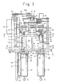
- the pneumatic cylinder mechanism 43 is actuated by this signal to displace the yarn traverse cam 4a in the arrowed direction from a position shown by chain line in Fig. 2 at which the normal yarn traverse motion for yarn winding is carried out to another position shown by a solid line.
- the turned traverse guide 5 can traverse beyond the normal traverse range to reach the yarn holding device 38 provided outside of the base end of the empty bobbin 3b, so that the yarn Y is brought to the yarn holding device 38.
- the yarn Y is caught by the hooks 34 at the periphery of the annular clamp member 33.
- a yarn portion caught by the hooks 35 is clamped, as a starting end of the winding, between the clamp member 33 and the friction member 36 on the end surface of the bobbin chuck and then raised in the rotational direction of the bobbin in the area other than the normal winding position.
- a yarn portion Y' extending from the full bobbin 3a to the empty bobbin 3b is suitably tensioned so that it is pressed onto an cutting edge 48 arranged in a yarn path and severed.
- the yarn transfer from the full bobbin 3a to the empty bobbin 3b is completed.
- a limit switch 47 (a third detecting means) is actuated to issue a detection signal by which the pneumatic cylinder mechanism 43 moves in the reverse direction and causes the yarn traverse cam 4a to resume the original position, whereby the traverse guide 5 is subjected to the normal traverse motion so that the yarn winding on the empty bobbin 3b is restarted.
- Fig. 8 diagrammatically illustrates the change of a traverse range of the traverse guide 5 according to the axial shift of the yarn traverse cam 4a.
- the empty bobbin is promptly transferred to the winding-start position A by a continuous rotation of the stepping motor 9 caused by the continuous input of a predetermined number of pulses from a timer or a counter.
- the generation of these pulses is started when the limit switch 46 (the second detecting means) has been actuated by a first traverse motion after the return of the traverse am to the normal position, and hereafter, the yarn winding at a normal speed begins.
- the continuous rotation of the stepping motor may be caused by the utilization of an on/off motion of the limit switch 32 while adjusting an engagement angle between the limit switch 32 and the projections 31a, 31b.
- the full bobbin 3a replaced by the empty bobbin 3b is gradually rotated along a path of the orbital motion by the stepwise movement of the stepping motor 9 as the diameter of the bobbin 3b increases, and reaches the doffing-start position D as shown in Fig. 1.
- the annular clamp member 33 is distanced from the end surface of the bobbin by the contact of the cam follower 40 with the arcuate cam 41, so that the clamped yarn end is released. Since the full bobbin 3a still remains in the braked condition at this time, the operator can remove the full bobbin 3a from the bobbin chuck 1a to replace with a fresh empty bobbin, to preparate for the next operation.
- limit switches 46, 47 are arranged as second and third detecting means, in the vicinity of the turning points of the traverse guide 5.
- a disc may be provided in place of the limit switches, and is associated with the rotation of the yarn traverse cam 4a to rotate once per each reciprocation of the traverse motion.
- the position of the traverse guide 5 can be indirectly determined by detecting the angular position of the disc through two limit switches.
- the cam follower 61 of the spindle 11 subjected to the orbital motion in the counterclockwise direction is outside of the operating area of the plate cam 62 until the empty bobbin 3b starting from the winding-start position A and passing the full bobbin position B has reached a point midway between the latter and the yarn-transfer symmetrical position C. Therefore, the respective members of the clutch mechanism 50 occupy positions shown in Fig. 7(a), whereby the pulley 12 and the spindle 11 are completely engaged with each other, i.e., a driving torque derived from the pulley 12 is fully transmitted to the spindle 11.
- the bobbin chuck carrying the empty bobbin is driven with a transmitted torque smaller than that necessary for maintaining the normal yarn winding tension, while generating slip due to the incomplete clutch engagement relationship between the spindle 11 and the pulley 12.
- the clutch resumes the full engagement state whereby the newly mounted empty bobbin is subjected to the quick orbital motion toward the yarn-transfer position F, as stated before, while rotating on its own axis at a high speed.
- a speed-variable motor is used as a motor 23 for driving the spindle, which speed is adjusted by a signal corresponding to the detected yarn tension, a balance point deviates to the acceleration side in accordance with a decrease of yarn tension caused by the lowering of a rotation torque of the full bobbin due to the abovesaid half-clutch state. Therefore the peripheral speed of the empty bobbin increases to become equal to that of the full bobbin, or larger than the latter, so that yarn slack is prevented before the yarn is taken up by the empty bobbin. In addition, a suitable tension is applied thereby on a yarn length bridging both bobbins, and thus the yarn severing operation can be correctly carried out.
- Fig. 9 illustrates another embodiment of a mechanism for severing a yarn length bridging both bobbins.
- An arm 64 is pivoted at a base end on the periphery of the turret disc 2, while biased by a spring in the direction of arrow U.
- a yarn cutting edge 48 At the tip end of the arm 64 are secured a yarn cutting edge 48 and a lever 65 in parallel thereto and pivoted at an end thereof.
- the lever 65 is always biased in the direction of arrow V by means of a coil spring 66.
- a cam follower 69 is secured on the tip end of a rod 67 projected from a midportion of the arm 64 and engaged with a cam piece 68 fixed on the from 6 to pivot the arm.
- the arm 64 stands up to occupy an operative position shown in solid line due to the engagement of the cam follower 69 with the cam piece 68 and the yarn cutting edge 48 occupies a position on which the bridge yarn is crossed.
- the bridge yarn Y' connected with the full bobbin and held by the hook 34 is brought into contact with the lever 65 and pushed thereby toward the tip end of the bobbin chuck 1a carrying the full bobbin so that it does not fall down from the end surface of the full bobbin.
- the bridge yarn causes the lever 65 to rotate against the force of the spring 66 and finally touches the yarn cutting edge 48 to be severed.
- FIG. 10 An improvement of the abovesaid basic structure of means for holding a yarn end during the yarn-transfer operation is illustrated in Fig. 10.
- an annular clamp member 33 and a friction member 36 each provided at an end of the bobbin chuck are pressed against each other by a spring 37 and a yarn is pushed into a V-shaped gap between both the members 33 and 36 when the yarn is to be clamped on the end of an empty bobbin during the yarn-transfer operation.
- the operation of this structure is rather unreliable because it relies exclusively on the yarn winding tension.
- the illustrated embodiment aims to achieve a reliable clamp of the yarn end.
- a guide rod 147 is supported by a bracket (not shown) in parallel to the operative direction of a yarn traverse guide 5, and a slide member 149 carrying a contact piece 148 is slidably mounted thereon.
- the slide member 149 is connected, via an L-shaped plate 150 shown in chain line, with the upper end of an actuating lever 45 carried on the tip end of a piston rod 44 of a pneumatic cylinder mechanism 43.
- the contact piece 148 is reciprocated along with the slide member 149 in accordance with the extending/retracting stroke of the piston rod 44 when the yarn traverse cam 4a is shifted during the yarn-transfer operation.
- the contact piece 148 is secured at a position engageable with the cam follower 40 of the bobbin chuck 1a or 1b occupying the yarn-transfer position F just before the completion of the retracting stroke of the piston rod 44 and pushes the cam follower 40 in the righthand direction in Fig. 10 to force the annular clamp member 33 away from the friction member 36 via the actuating lever 39, against the compression spring 37.
- An embodiment illustrated in Figs. 11 through 14 is that in which a mechanism is added to the aforesaid basic structure, suitable for forming bunch wind of a predetermined number at an end of the empty bobbin during the yarn-transfer operation.
- means for forming a bunch wind in the prior art has the respective motors for separately driving a yarn transverse cam and a bobbin chuck, and only the motor for driving the yarn traverse cam is temporarily made to stop at the beginning stage of yarn winding on an empty bobbin so that a straight bunch wind is formed on the end of the empty bobbin.
- this mechanism needs an expensive control device such as a computer for synchronizing the rotation of the yarn traverse cam with that of a spindle carrying the bobbin chuck, whereby the total cost of the winder is increased.
- a bunch lever with a hook for preventing a yarn from a traverse motion regardless of the rotation of a yarn traverse cam and a motion of a traverse guide is provided on a bobbin chuck, which is displaced to the operative position if necessary, where the yarn is restrained from the traverse motion and forms the straight bunch wind on the bobbin before the yarn is released therefrom, and subjected to the winding operation under the normal traverse motion.
- This device has a advantage that the rotational synchronization is easily obtained between the yarn traverse cam and the bobbin chuck, through a simple mechanism, but needs an exclusive drive source and a complicated mechanism for displacing the bunch lever between an operative position and a non-operative position at the desired moment.
- An object of the third embodiment according to the present invention is to solve the abovesaid problems in the prior art and provide a simple mechanism by the utilization of a pneumatic cylinder originally used for shifting yarn traverse cam during the yarn transfer operation, as a drive source for actuating the bunch lever.
- a shaft 246 is rotatably supported by an upper bracket 247 (Fig. 14), and the bunch lever 48 having a hook portion 248a for preventing a traverse motion of a yarn Y is fixed at a lower end of the shaft 247 to be rotatable in the horizontal plane together with the shaft 247.
- the hook portion 248a is positioned beneath a path of the yarn traverse guide 5 exceeding the normal traverse range.
- a lever 249 which rotatably biases the bunch lever 248 by a spring 250 in the direction indicated by an arrow X in Fig. 13, so that the bunch lever 248 restrains the yarn Y.
- An intermediate lever 251 is supported on the upper bracket 246 at a midportion thereof by a pin 251c and is engaged with the side of the lever 249 via a small roller 251a secured at one end of the lever 251.
- a tip end of a push rod 253 passing through a guide hole 252 provided on the frame 6 is brought into contact with a vertical surface 251b at the other end of the intermediate lever 251.
- the push rod 253 is arranged in line with the piston rod 44 of the pneumatic cylinder mechanism 43. When the piston rod is retracted, as shown by a solid line in Fig.
- the push rod 253 is displaced backward by a bias force of the spring 250 acting on the lever 249 until a double nut 254 screwed with a thread portion 253a in a tip end area of the rod 253 is in contact with the edge of the guide hole 252.
- the bunch lever 248 is rotated counterclockwise, as shown by a solid line in Fig. 13, together with the shaft 247 to occupy an operative position at which a traverse motion of the yarn Y is prevented.
- the push rod 44 When the piston rod 44 is in an extended condition, the push rod 44 is pushed out by a tip end of the piston rod 44 and the lever 249 is rotated clockwise against the bias force of the spring 250 through the intermediate lever 251 so that the bunch lever 248 together with the shaft 247 occupies a waiting position, as show by a dotted line, at which the bunch lever does not interferes with a yarn path.
- An additional plate 255 is fixed on the back surface of a beam 256 provided with a rail for guiding the connecting rod 4d of the yarn traverse device 4.
- the lower edge of the plate 255 is positioned beneath the bunch lever 248 so that the yarn Y can be easily released from the hook portion 248a when the bunch lever 248 is rotated to occupy the waiting position while holding the yarn Y at the hook portion 248a.
- the limit switch 47 i.e., the third detecting means, is actuated to switch-on the timer, and maintains this state until a predetermined number of bunch windings are formed.
- the timer is switched off and a flow route of a solenoid valve (not shown) for supplying compressed air to the pneumatic cylinder 43 is changed to another route so that the piston rod 44 is projected, whereby the push rod 253 is pushed by the piston rod 44 to rotate the bunch lever 248 toward the waiting position as shown by a chain line in Fig. 13.
- a solenoid valve (not shown) for supplying compressed air to the pneumatic cylinder 43 is changed to another route so that the piston rod 44 is projected, whereby the push rod 253 is pushed by the piston rod 44 to rotate the bunch lever 248 toward the waiting position as shown by a chain line in Fig. 13.
- the yarn Y is released from the hook portion 248a, and the traverse guide 5 resumes the proper traverse position so that the normal yarn winding can be carried out.
- An operation sequence of a turret type winder according to the present invention stated above can be controlled, for example, by an electric circuit illustrated in Fig. 15, as described below.
- the continuous drive of the stepping motor 9 lasts for a predetermined period set in the timer TM2. Accordingly, if this period is properly selected, the spindle can travel from the yarn-transfer position F to the winding-start position A and stop at the latter position.
- Fig. 16 is a time chart illustrating an operative sequence of the respective elements in a winder with a bunch winding device according to the present invention.
- a yarn traverse cam is axially shifted momentarily to a basic end of a bobbin by a predetermined distance, whereby a yarn is displaced out of a normal traverse range to the basic end of the bobbin and caught by a yarn holding means provided on a bobbin chuck, which yarn is severed between the yarn holding means and a full bobbin now braked by a clutch mechanism with a brake. That is, a yarn transfer operation can be smoothly carried out without using an exclusive yarn transfer guide.
- a spindle carrying a full bobbin is stepwisely braked to decrease the rotational speed thereof, by a torque-adjustable clutch/brake mechanism so that the rotational speed of a common motor driving both spindles is increased more than once in the normal winding operation.
- a yarn slack due to the lowering of a winding speed of a spindle carrying an empty bobbin which is liable to occur during the yarn transfer from the full bobbin to the empty bobbin, can be eliminated.
- a cam provided along a path of the orbital motion of a turret disc is used as means for automatically actuating this clutch mechanism during the orbital motion of the spindle/bobbin chuck, the structure thereof can be simplified.
- the present invention is suitably applicable to a production or take-up process for a ceramics fiber or a carbon fiber, a sizing process for a tire cord, or a rewinding process for dividing a large yarn package into a plurality of small size yarn packages.
Landscapes
- Engineering & Computer Science (AREA)
- Textile Engineering (AREA)
- Replacing, Conveying, And Pick-Finding For Filamentary Materials (AREA)
- Winding Filamentary Materials (AREA)
Abstract
Priority Applications (2)
| Application Number | Priority Date | Filing Date | Title |
|---|---|---|---|
| EP95107158A EP0673871B1 (fr) | 1989-09-27 | 1990-09-27 | Dispositif de bobinage de fil du type tourelle |
| EP95107159A EP0673872B1 (fr) | 1989-09-27 | 1990-09-27 | Dispositif de bobinage de fil du type tourelle |
Applications Claiming Priority (11)
| Application Number | Priority Date | Filing Date | Title |
|---|---|---|---|
| JP24919289A JP2724887B2 (ja) | 1989-09-27 | 1989-09-27 | タレット型巻糸装置 |
| JP24919189A JP2761943B2 (ja) | 1989-09-27 | 1989-09-27 | タレット型巻糸装置 |
| JP249191/89 | 1989-09-27 | ||
| JP249192/89 | 1989-09-27 | ||
| JP3298290U JP2525109Y2 (ja) | 1990-03-29 | 1990-03-29 | タレット型巻糸機の糸端保持装置 |
| JP32982/90U | 1990-03-29 | ||
| JP170260/90 | 1990-06-29 | ||
| JP17026090A JP2782554B2 (ja) | 1990-06-29 | 1990-06-29 | タレット型巻糸装置 |
| JP89739/90U | 1990-08-28 | ||
| JP8973990U JP2535327Y2 (ja) | 1990-08-28 | 1990-08-28 | タレット型巻糸機のバンチ巻き装置 |
| PCT/JP1990/001244 WO1991004937A1 (fr) | 1989-09-27 | 1990-09-27 | Dispositif de bobinage de fil du type tourelle |
Related Child Applications (4)
| Application Number | Title | Priority Date | Filing Date |
|---|---|---|---|
| EP95107159A Division EP0673872B1 (fr) | 1989-09-27 | 1990-09-27 | Dispositif de bobinage de fil du type tourelle |
| EP95107158A Division EP0673871B1 (fr) | 1989-09-27 | 1990-09-27 | Dispositif de bobinage de fil du type tourelle |
| EP95107158.8 Division-Into | 1995-05-11 | ||
| EP95107159.6 Division-Into | 1995-05-11 |
Publications (3)
| Publication Number | Publication Date |
|---|---|
| EP0450085A1 true EP0450085A1 (fr) | 1991-10-09 |
| EP0450085A4 EP0450085A4 (en) | 1993-03-31 |
| EP0450085B1 EP0450085B1 (fr) | 1997-10-22 |
Family
ID=27521474
Family Applications (3)
| Application Number | Title | Priority Date | Filing Date |
|---|---|---|---|
| EP90914421A Expired - Lifetime EP0450085B1 (fr) | 1989-09-27 | 1990-09-27 | Dispositif de bobinage de fil du type tourelle |
| EP95107158A Expired - Lifetime EP0673871B1 (fr) | 1989-09-27 | 1990-09-27 | Dispositif de bobinage de fil du type tourelle |
| EP95107159A Expired - Lifetime EP0673872B1 (fr) | 1989-09-27 | 1990-09-27 | Dispositif de bobinage de fil du type tourelle |
Family Applications After (2)
| Application Number | Title | Priority Date | Filing Date |
|---|---|---|---|
| EP95107158A Expired - Lifetime EP0673871B1 (fr) | 1989-09-27 | 1990-09-27 | Dispositif de bobinage de fil du type tourelle |
| EP95107159A Expired - Lifetime EP0673872B1 (fr) | 1989-09-27 | 1990-09-27 | Dispositif de bobinage de fil du type tourelle |
Country Status (4)
| Country | Link |
|---|---|
| US (2) | US5228630A (fr) |
| EP (3) | EP0450085B1 (fr) |
| DE (3) | DE69033206T2 (fr) |
| WO (1) | WO1991004937A1 (fr) |
Cited By (5)
| Publication number | Priority date | Publication date | Assignee | Title |
|---|---|---|---|---|
| WO1997007045A1 (fr) * | 1995-08-16 | 1997-02-27 | Barmag Ag | Procede permettant de mettre un fil en bobine |
| CN1935614B (zh) * | 2005-09-20 | 2012-07-04 | 村田机械株式会社 | 纤维机械用卷取装置 |
| DE102012107015A1 (de) | 2011-08-03 | 2013-02-07 | Oerlikon Textile Gmbh & Co. Kg | Aufspulvorrichtung |
| DE102011115051A1 (de) | 2011-10-07 | 2013-04-11 | Oerlikon Textile Gmbh & Co. Kg | Verfahren und Vorrichtung zum kontinuierlichen Aufwickeln eines bandförmigen Spulgutes |
| FR3068341A1 (fr) * | 2017-07-03 | 2019-01-04 | Spoolex | Dispositif et procede d'enroulage et de transfert d'une bandelette a partir d'une bobine pleine jusqu'a une bobine vide |
Families Citing this family (32)
| Publication number | Priority date | Publication date | Assignee | Title |
|---|---|---|---|---|
| US5489067A (en) * | 1989-09-27 | 1996-02-06 | Kamitsu Seisakusho, Ltd. | Turret type precision yarn winder |
| JPH05246622A (ja) * | 1992-03-02 | 1993-09-24 | Koutsu Seisakusho:Kk | タレット型巻糸装置 |
| TW252998B (fr) * | 1992-03-05 | 1995-08-01 | Barmag Barmer Maschf | |
| DE19708936A1 (de) * | 1997-03-05 | 1998-09-10 | Novibra Gmbh | Fadenchangiervorrichtung an einer Kreuzspulen herstellenden Textilmaschine |
| US6158689A (en) * | 1997-07-10 | 2000-12-12 | Barmag-Spinnzwirn Gmbh | Yarn winding apparatus and method |
| CN1163395C (zh) * | 1997-09-11 | 2004-08-25 | 苏拉有限及两合公司 | 卷绕机及丝线的切换方法 |
| CN1251951C (zh) * | 1998-09-04 | 2006-04-19 | 东丽株式会社 | 合成纤维的卷绕方法和装置以及纱线卷装的使用方法 |
| AU2613900A (en) * | 1999-01-15 | 2000-08-01 | Saco Lowell, Inc. | Winder machine |
| GB9912268D0 (en) | 1999-05-27 | 1999-07-28 | Meltog Ltd | Axial displacement mechanism |
| DE10020664A1 (de) * | 2000-04-27 | 2001-10-31 | Schlafhorst & Co W | Verfahren zum Betreiben einer Kreuzspulen herstellenden Textilmaschine |
| US6366044B2 (en) * | 2000-07-04 | 2002-04-02 | Asmo Co., Ltd. | Rotational-position sensing device and windshield wiper system having the same |
| US6343763B1 (en) * | 2000-07-21 | 2002-02-05 | Kt Equipment (International) Inc. | Transferring winding from a filled cylindrical package of an elongate material to an empty core |
| ES2224981T3 (es) * | 2000-09-06 | 2005-03-16 | Nan Ya Plastics Corporation | Bobina con una ranura cortada en forma de v que se estrecha gradualmente, con una superficie rugosa que comprende escamas invertidas. |
| JP2002114446A (ja) * | 2000-10-03 | 2002-04-16 | Murata Mach Ltd | 紡糸巻取機 |
| DE10223484B4 (de) * | 2002-05-27 | 2008-04-30 | Georg Sahm Gmbh & Co. Kg | Verfahren und Spulmaschine zum Aufwickeln eines kontinuierlich zulaufenden Fadens auf eine Hülse zu einer Spule |
| DE102005044487A1 (de) * | 2005-09-16 | 2007-03-22 | Maschinenfabrik Rieter Ag | Aufwindevorrichtung für Endlosfäden |
| US20080000782A1 (en) * | 2006-06-29 | 2008-01-03 | Parr Guy H | Paint roller storage system and apparatus |
| US7775732B2 (en) * | 2006-11-30 | 2010-08-17 | International Business Machines Corporation | Multi-roll paper supply for printer |
| PL2185454T3 (pl) * | 2007-09-07 | 2011-09-30 | Lohia Starlinger Ltd | Urządzenie do wprowadzania włókna do urządzenia chwytającego automatycznej nawijarki typu rewolwerowego |
| DE202010008846U1 (de) | 2010-10-20 | 2010-12-23 | Starlinger & Co Ges.M.B.H. | Spulmaschine |
| JP2012144323A (ja) * | 2011-01-11 | 2012-08-02 | Tmt Machinery Inc | 紡糸巻取装置及び紡糸巻取設備 |
| CH709606A1 (de) * | 2014-05-08 | 2015-11-13 | Rieter Ag Maschf | Verfahren zum Betrieb einer Textilmaschine, die der Herstellung von Vorgarn dient, sowie Textilmaschine. |
| EP3371083B1 (fr) | 2015-11-04 | 2019-08-07 | Lohia, Siddharth | Appareil et procédé pour réguler une tension d'enroulement en fonction d'un diamètre de bobine |
| WO2017093950A1 (fr) | 2015-12-03 | 2017-06-08 | Siddharth LOHIA | Procédé pour positionner une broche avec précision dans un enrouleur automatique de type tourelle |
| CN106516894A (zh) * | 2016-12-31 | 2017-03-22 | 常州三泰塑胶有限公司 | 双工位卷绕机 |
| TWI691452B (zh) * | 2019-04-16 | 2020-04-21 | 泰能機器工業股份有限公司 | 捲線機構 |
| CN110902473B (zh) * | 2019-12-11 | 2021-09-07 | 湖州创塑新材科技有限公司 | 一种布料纺织线全自动绕线装置 |
| EP3917866A1 (fr) | 2020-01-20 | 2021-12-08 | Lohia Corp Limited | Appareil d'enroulement et procédé pour enrouler un fil ou des bandes de film coupé arrivant en continu |
| CN111645136B (zh) * | 2020-06-12 | 2021-12-24 | 永城盛大印刷科技股份有限公司 | 一种印刷品废弃物再利用回收处理方法 |
| CN112141815B (zh) * | 2020-10-20 | 2022-06-07 | 湖南腾博复合材料有限公司 | 一种环式结构型调节绕线装置 |
| CN115636300B (zh) * | 2022-10-13 | 2023-04-18 | 武汉市园林建筑工程有限公司 | 一种变电站线缆收卷加工装置 |
| USD1107542S1 (en) * | 2025-04-02 | 2025-12-30 | Hefei Zhuo'ao Trading Co., Ltd. | Winding machine |
Family Cites Families (20)
| Publication number | Priority date | Publication date | Assignee | Title |
|---|---|---|---|---|
| DE374536C (de) * | 1921-05-15 | 1923-04-25 | R & O Lux | OEsensetzmaschine mit auswechselbarem OEsenbehaelter nebst Zufuehrvorrichtung |
| DE553945C (de) * | 1933-05-12 | 1932-07-02 | Ernst Berl Dr | Vorrichtung zum selbsttaetigen Auswechseln der Spulen an Kunstseidenspinnmaschinen mit schwenkbaren Spulentraegern |
| FR1117576A (fr) * | 1954-12-27 | 1956-05-24 | Telecommunications Sa | Enrouloir continu automatique |
| DE1040690B (de) * | 1955-12-06 | 1958-10-09 | Werner Walter Luetcke | Maschine zum Aufwickeln von Draehten und sonstigem spulfaehigem Gut |
| US3126165A (en) * | 1961-01-31 | 1964-03-24 | Jan van euk | |
| DE1257374B (de) * | 1963-06-20 | 1967-12-28 | Schuller Gmbh Glaswerk | Verfahren und Vorrichtung zum fortlaufenden Aufspulen von Faserbaendern aus Glasstapelfasern |
| US3490707A (en) * | 1968-06-07 | 1970-01-20 | Loveshaw Corp | Strand or yarn forming winder |
| GB1270823A (en) * | 1969-05-14 | 1972-04-19 | Kishinevsky Nii Elektropriboro | A device for winding microwave in the course of manufacturing the same |
| US3856222A (en) * | 1969-10-03 | 1974-12-24 | Rieter Ag Maschf | Method of automatically changing winding tubes and winding apparatus for implementing the aforesaid method and improved spool doffing mechanism |
| JPS499413B1 (fr) * | 1970-12-24 | 1974-03-04 | ||
| JPS499414B1 (fr) * | 1970-12-24 | 1974-03-04 | ||
| JPS5417860B2 (fr) * | 1973-12-24 | 1979-07-03 | ||
| CH618401A5 (fr) * | 1975-06-12 | 1980-07-31 | Barmag Barmer Maschf | |
| JPS5240635A (en) * | 1975-09-25 | 1977-03-29 | Mitsubishi Heavy Ind Ltd | Thread bunch change process of automatic winder |
| JPS5378346A (en) * | 1976-12-22 | 1978-07-11 | Toyoda Automatic Loom Works | Method of switching strand in glass fiber winder |
| JPS54114675A (en) * | 1978-02-28 | 1979-09-06 | Toray Ind Inc | Turret type thread stripe winder |
| US4138069A (en) * | 1978-05-04 | 1979-02-06 | Corning Glass Works | Winding apparatus for glass optical filaments |
| IT1151367B (it) * | 1981-04-04 | 1986-12-17 | Barmag Barmer Maschf | Procedimento per il cambio della bobina durante l'avvolgimento di un filo alimentato in continuazione,nonche' dispositivo d'avvolgimento |
| US4917319A (en) * | 1988-07-06 | 1990-04-17 | Barmag Ag | Method of winding yarn packages |
| DE8916288U1 (de) * | 1988-12-22 | 1997-05-22 | Barmag Ag, 42897 Remscheid | Aufspulmaschine |
-
1990
- 1990-09-27 EP EP90914421A patent/EP0450085B1/fr not_active Expired - Lifetime
- 1990-09-27 DE DE69033206T patent/DE69033206T2/de not_active Expired - Lifetime
- 1990-09-27 DE DE69033392T patent/DE69033392T2/de not_active Expired - Lifetime
- 1990-09-27 EP EP95107158A patent/EP0673871B1/fr not_active Expired - Lifetime
- 1990-09-27 US US07/689,950 patent/US5228630A/en not_active Expired - Lifetime
- 1990-09-27 WO PCT/JP1990/001244 patent/WO1991004937A1/fr not_active Ceased
- 1990-09-27 EP EP95107159A patent/EP0673872B1/fr not_active Expired - Lifetime
- 1990-09-27 DE DE69031617T patent/DE69031617T2/de not_active Expired - Lifetime
-
1993
- 1993-04-22 US US08/052,342 patent/US5344090A/en not_active Expired - Lifetime
Cited By (9)
| Publication number | Priority date | Publication date | Assignee | Title |
|---|---|---|---|---|
| WO1997007045A1 (fr) * | 1995-08-16 | 1997-02-27 | Barmag Ag | Procede permettant de mettre un fil en bobine |
| CN1935614B (zh) * | 2005-09-20 | 2012-07-04 | 村田机械株式会社 | 纤维机械用卷取装置 |
| DE102012107015A1 (de) | 2011-08-03 | 2013-02-07 | Oerlikon Textile Gmbh & Co. Kg | Aufspulvorrichtung |
| WO2013017694A1 (fr) | 2011-08-03 | 2013-02-07 | Oerlikon Textile Gmbh & Co. Kg | Dispositif de bobinage |
| CN103717519A (zh) * | 2011-08-03 | 2014-04-09 | 欧瑞康纺织有限及两合公司 | 络筒装置 |
| CN103717519B (zh) * | 2011-08-03 | 2016-06-29 | 欧瑞康纺织有限及两合公司 | 络筒装置 |
| DE102011115051A1 (de) | 2011-10-07 | 2013-04-11 | Oerlikon Textile Gmbh & Co. Kg | Verfahren und Vorrichtung zum kontinuierlichen Aufwickeln eines bandförmigen Spulgutes |
| FR3068341A1 (fr) * | 2017-07-03 | 2019-01-04 | Spoolex | Dispositif et procede d'enroulage et de transfert d'une bandelette a partir d'une bobine pleine jusqu'a une bobine vide |
| WO2019007585A1 (fr) * | 2017-07-03 | 2019-01-10 | Spoolex | Dispositif et procede d'enroulage et de transfert d'une bandelette a partir d'une bobine pleine jusqu'a une bobine vide |
Also Published As
| Publication number | Publication date |
|---|---|
| DE69033206D1 (de) | 1999-08-12 |
| EP0673872B1 (fr) | 1999-07-07 |
| DE69033206T2 (de) | 1999-12-09 |
| DE69031617D1 (de) | 1997-11-27 |
| EP0673871B1 (fr) | 1999-12-08 |
| EP0673872A2 (fr) | 1995-09-27 |
| DE69033392D1 (de) | 2000-01-13 |
| EP0673872A3 (fr) | 1995-11-29 |
| EP0450085B1 (fr) | 1997-10-22 |
| WO1991004937A1 (fr) | 1991-04-18 |
| EP0673871A2 (fr) | 1995-09-27 |
| DE69031617T2 (de) | 1998-04-02 |
| US5228630A (en) | 1993-07-20 |
| US5344090A (en) | 1994-09-06 |
| EP0450085A4 (en) | 1993-03-31 |
| EP0673871A3 (fr) | 1995-11-29 |
| DE69033392T2 (de) | 2000-03-30 |
Similar Documents
| Publication | Publication Date | Title |
|---|---|---|
| US5228630A (en) | Turret type yarn winder | |
| US5526995A (en) | Yarn winding method | |
| US6045081A (en) | Method and apparatus for winding a continuously advancing yarn | |
| US4948057A (en) | Device and process to guide, hold and convey a yarn during bobbin replacement | |
| US5016829A (en) | Takeup machine | |
| EP0606900B1 (fr) | Bobinoir pour fil | |
| US4083505A (en) | Spinning machine with thread applying device | |
| US3184174A (en) | Yarn-spool winding machine with automatic spool-exchanging device | |
| US5489067A (en) | Turret type precision yarn winder | |
| JPH10167577A (ja) | 綾巻きパッケージを製造する繊維機械の巻返しユニット | |
| US4552313A (en) | Method and apparatus for switching yarn in turret-type winder | |
| JPS581213B2 (ja) | オ−プンエンドセイボウキノ クチツケホウホウオヨビソウチ | |
| JPH0578012A (ja) | 糸の巻取装置 | |
| JP2761943B2 (ja) | タレット型巻糸装置 | |
| JPH03111377A (ja) | 自動ワインダ | |
| JPS5938452Y2 (ja) | 繊維機械特にオ−プンエンド紡糸機の操作の開始および停止時に調節可能な時間間隔で個々の群の操作手段を始動、停止するタイムシ−ケンスを確保する装置 | |
| US3802637A (en) | Automatic winding machine and method of operation thereof | |
| JPH0761829B2 (ja) | 紡糸用巻取機 | |
| US4146186A (en) | Spinning machine with thread applying device | |
| JP2875183B2 (ja) | ターレット式自動切替巻取機における糸条切替方法 | |
| JP2535327Y2 (ja) | タレット型巻糸機のバンチ巻き装置 | |
| JP3675848B2 (ja) | タレット型巻取機の糸切替装置 | |
| JP2782554B2 (ja) | タレット型巻糸装置 | |
| JP2893479B2 (ja) | バンチ巻き形成装置 | |
| RU2078734C1 (ru) | Способ намотки химической нити |
Legal Events
| Date | Code | Title | Description |
|---|---|---|---|
| PUAI | Public reference made under article 153(3) epc to a published international application that has entered the european phase |
Free format text: ORIGINAL CODE: 0009012 |
|
| 17P | Request for examination filed |
Effective date: 19910518 |
|
| AK | Designated contracting states |
Kind code of ref document: A1 Designated state(s): CH DE FR GB LI NL |
|
| A4 | Supplementary search report drawn up and despatched |
Effective date: 19930205 |
|
| AK | Designated contracting states |
Kind code of ref document: A4 Designated state(s): CH DE FR GB LI NL |
|
| 17Q | First examination report despatched |
Effective date: 19941102 |
|
| GRAG | Despatch of communication of intention to grant |
Free format text: ORIGINAL CODE: EPIDOS AGRA |
|
| GRAH | Despatch of communication of intention to grant a patent |
Free format text: ORIGINAL CODE: EPIDOS IGRA |
|
| GRAH | Despatch of communication of intention to grant a patent |
Free format text: ORIGINAL CODE: EPIDOS IGRA |
|
| GRAA | (expected) grant |
Free format text: ORIGINAL CODE: 0009210 |
|
| AK | Designated contracting states |
Kind code of ref document: B1 Designated state(s): CH DE FR GB LI NL |
|
| XX | Miscellaneous (additional remarks) |
Free format text: TEILANMELDUNG 95107158.8 EINGEREICHT AM 27/09/90. |
|
| REG | Reference to a national code |
Ref country code: CH Ref legal event code: EP |
|
| REF | Corresponds to: |
Ref document number: 69031617 Country of ref document: DE Date of ref document: 19971127 |
|
| ET | Fr: translation filed | ||
| REG | Reference to a national code |
Ref country code: CH Ref legal event code: NV Representative=s name: E. BLUM & CO. PATENTANWAELTE |
|
| PLBE | No opposition filed within time limit |
Free format text: ORIGINAL CODE: 0009261 |
|
| STAA | Information on the status of an ep patent application or granted ep patent |
Free format text: STATUS: NO OPPOSITION FILED WITHIN TIME LIMIT |
|
| 26N | No opposition filed | ||
| REG | Reference to a national code |
Ref country code: GB Ref legal event code: IF02 |
|
| REG | Reference to a national code |
Ref country code: CH Ref legal event code: PFA Owner name: KAMITSU SEISAKUSHO LTD. Free format text: KAMITSU SEISAKUSHO LTD.#8-13, MORIMOTO 1-CHOME#ITAMI-SHI, HYOGO-664 (JP) -TRANSFER TO- KAMITSU SEISAKUSHO LTD.#8-13, MORIMOTO 1-CHOME#ITAMI-SHI, HYOGO-664 (JP) |
|
| PGFP | Annual fee paid to national office [announced via postgrant information from national office to epo] |
Ref country code: FR Payment date: 20090807 Year of fee payment: 20 |
|
| PGFP | Annual fee paid to national office [announced via postgrant information from national office to epo] |
Ref country code: NL Payment date: 20090928 Year of fee payment: 20 Ref country code: CH Payment date: 20090811 Year of fee payment: 20 Ref country code: GB Payment date: 20090923 Year of fee payment: 20 |
|
| PGFP | Annual fee paid to national office [announced via postgrant information from national office to epo] |
Ref country code: DE Payment date: 20090925 Year of fee payment: 20 |
|
| REG | Reference to a national code |
Ref country code: NL Ref legal event code: V4 Effective date: 20100927 |
|
| REG | Reference to a national code |
Ref country code: CH Ref legal event code: PL |
|
| REG | Reference to a national code |
Ref country code: GB Ref legal event code: PE20 Expiry date: 20100926 |
|
| PG25 | Lapsed in a contracting state [announced via postgrant information from national office to epo] |
Ref country code: GB Free format text: LAPSE BECAUSE OF EXPIRATION OF PROTECTION Effective date: 20100926 |
|
| PG25 | Lapsed in a contracting state [announced via postgrant information from national office to epo] |
Ref country code: NL Free format text: LAPSE BECAUSE OF EXPIRATION OF PROTECTION Effective date: 20100927 |
|
| PG25 | Lapsed in a contracting state [announced via postgrant information from national office to epo] |
Ref country code: DE Free format text: LAPSE BECAUSE OF EXPIRATION OF PROTECTION Effective date: 20100927 |