EP0450154A1 - Utilisation d'un element de protection pour la protection pour couches d'étanchéité de dépôts d'ordures et procédé pour rendre des dépôts d'ordures étanches - Google Patents
Utilisation d'un element de protection pour la protection pour couches d'étanchéité de dépôts d'ordures et procédé pour rendre des dépôts d'ordures étanches Download PDFInfo
- Publication number
- EP0450154A1 EP0450154A1 EP90121719A EP90121719A EP0450154A1 EP 0450154 A1 EP0450154 A1 EP 0450154A1 EP 90121719 A EP90121719 A EP 90121719A EP 90121719 A EP90121719 A EP 90121719A EP 0450154 A1 EP0450154 A1 EP 0450154A1
- Authority
- EP
- European Patent Office
- Prior art keywords
- sand
- element according
- protective
- protection
- protective element
- Prior art date
- Legal status (The legal status is an assumption and is not a legal conclusion. Google has not performed a legal analysis and makes no representation as to the accuracy of the status listed.)
- Granted
Links
- 238000007789 sealing Methods 0.000 title claims abstract description 25
- 238000000034 method Methods 0.000 title claims description 8
- 239000004576 sand Substances 0.000 claims abstract description 37
- 239000013590 bulk material Substances 0.000 claims abstract description 6
- 230000001681 protective effect Effects 0.000 claims description 65
- 239000010410 layer Substances 0.000 claims description 20
- 239000004753 textile Substances 0.000 claims description 19
- 239000012528 membrane Substances 0.000 claims description 17
- 239000000463 material Substances 0.000 claims description 15
- 239000011241 protective layer Substances 0.000 claims description 14
- 230000000295 complement effect Effects 0.000 claims description 5
- 238000010276 construction Methods 0.000 claims description 4
- 239000004746 geotextile Substances 0.000 claims description 4
- 238000004078 waterproofing Methods 0.000 claims description 4
- 239000011248 coating agent Substances 0.000 claims description 3
- 238000000576 coating method Methods 0.000 claims description 3
- 125000006850 spacer group Chemical group 0.000 claims description 3
- 230000000087 stabilizing effect Effects 0.000 claims description 3
- 239000004744 fabric Substances 0.000 description 8
- 229920001903 high density polyethylene Polymers 0.000 description 5
- 239000004700 high-density polyethylene Substances 0.000 description 5
- 239000004033 plastic Substances 0.000 description 5
- 229920003023 plastic Polymers 0.000 description 5
- 238000009434 installation Methods 0.000 description 4
- 238000006073 displacement reaction Methods 0.000 description 3
- 238000004519 manufacturing process Methods 0.000 description 3
- 239000004698 Polyethylene Substances 0.000 description 2
- 239000004743 Polypropylene Substances 0.000 description 2
- 230000002349 favourable effect Effects 0.000 description 2
- 239000006260 foam Substances 0.000 description 2
- 230000000149 penetrating effect Effects 0.000 description 2
- 229920000573 polyethylene Polymers 0.000 description 2
- -1 polypropylene Polymers 0.000 description 2
- 229920001155 polypropylene Polymers 0.000 description 2
- 230000008569 process Effects 0.000 description 2
- 238000009941 weaving Methods 0.000 description 2
- 239000004793 Polystyrene Substances 0.000 description 1
- 230000009471 action Effects 0.000 description 1
- 238000005452 bending Methods 0.000 description 1
- 230000008859 change Effects 0.000 description 1
- 239000002131 composite material Substances 0.000 description 1
- 230000000694 effects Effects 0.000 description 1
- 238000011010 flushing procedure Methods 0.000 description 1
- 229910052500 inorganic mineral Inorganic materials 0.000 description 1
- 229920000092 linear low density polyethylene Polymers 0.000 description 1
- 239000004707 linear low-density polyethylene Substances 0.000 description 1
- 239000011707 mineral Substances 0.000 description 1
- 239000000203 mixture Substances 0.000 description 1
- 239000004745 nonwoven fabric Substances 0.000 description 1
- 230000035515 penetration Effects 0.000 description 1
- 229920000728 polyester Polymers 0.000 description 1
- 229920002223 polystyrene Polymers 0.000 description 1
- 230000007704 transition Effects 0.000 description 1
Images


Classifications
-
- E—FIXED CONSTRUCTIONS
- E02—HYDRAULIC ENGINEERING; FOUNDATIONS; SOIL SHIFTING
- E02B—HYDRAULIC ENGINEERING
- E02B3/00—Engineering works in connection with control or use of streams, rivers, coasts, or other marine sites; Sealings or joints for engineering works in general
- E02B3/04—Structures or apparatus for, or methods of, protecting banks, coasts, or harbours
- E02B3/12—Revetment of banks, dams, watercourses, or the like, e.g. the sea-floor
- E02B3/122—Flexible prefabricated covering elements, e.g. mats, strips
- E02B3/127—Flexible prefabricated covering elements, e.g. mats, strips bags filled at the side
-
- E—FIXED CONSTRUCTIONS
- E02—HYDRAULIC ENGINEERING; FOUNDATIONS; SOIL SHIFTING
- E02D—FOUNDATIONS; EXCAVATIONS; EMBANKMENTS; UNDERGROUND OR UNDERWATER STRUCTURES
- E02D31/00—Protective arrangements for foundations or foundation structures; Ground foundation measures for protecting the soil or the subsoil water, e.g. preventing or counteracting oil pollution
- E02D31/002—Ground foundation measures for protecting the soil or subsoil water, e.g. preventing or counteracting oil pollution
- E02D31/004—Sealing liners
Definitions
- the invention relates to a protective element for protecting waterproofing membranes in landfill construction and to a method for sealing landfill floors using this protective element.
- Protective elements are known which are designed as a composite material and consist of a carrier fabric with high strength and punch penetration force as well as a nonwoven fabric needled onto it. So they form a needle felt with high-strength carrier fabric and are placed on the sealing membrane with the fabric side up. They serve to carry and distribute part of the loads that occur. As a rule, however, a 10 d cm thick must then be used Protective layer made of sand. According to the older, not yet published German patent application P 40 ⁇ 0 ⁇ 0 ⁇ 653.0 ⁇ , this layer of sand can be dispensed with if the protective sheet is provided with a foam layer with a minimum thickness of 3 cm, preferably on the underside of the base fabric.
- a layer of sand is still ideal protection against damage to the waterproofing membrane due to the layer of gravel to be applied and the garbage.
- the installation of the protective layer made of sand causes considerable problems, since the use of construction machinery is not possible due to the risk of damage to the sealing layer, but on the other hand the installation with a wheelbarrow and shovel is too expensive.
- this installation by hand does not guarantee that the required minimum thickness is present everywhere, so that, for safety's sake, more sand is applied than is necessary for the protective effect.
- the layer of sand is displaced by the people entering it and their footprints in such a way that the thickness is too small in places.
- the invention has for its object to provide a protective layer for the protection of waterproofing membranes in landfill construction, which can be produced quickly and which ensures reliable protection even on embankments.
- a protective element which is designed as a flat container with a substantially constant height, in which a filling of sand or a sand-like bulk material is filled and which has such an extent that a large number of it in seamless bond can be laid to form a protective layer
- the protective element according to the invention is characterized by enormous advantages. It can be quickly and easily installed to form a protective layer by laying out the protective elements next to each other in a seamless bond.
- the size of the protective elements should be such that they can be carried by one or a maximum of two people. In particular if the flat container is designed to be closed on the top, no changes in the thickness of the sand layer are brought about by entering the person who is laying out the protective elements.
- the sand layer has the same thickness everywhere, so that the height of the sand layer and thus the protective element can also be reduced to the level that is just required, which leads to lower material consumption.
- the protective element has special advantages when covering embankments, since the sand cannot slide off. The same thickness of sand layer is thus also guaranteed there.
- the flat container is a closed, preferably completely filled sack with limp walls.
- a flat container designed in this way can be produced simply and inexpensively from various materials.
- spacers for example in the form of delimiting ribbons, should be arranged distributed over the interior of the sack so that the sack has its flat shape during filling and also during subsequent transport does not change, ie does not bulge.
- tear-resistant films are suitable as materials.
- the sacks are particularly suitable if the walls consist of a textile material which is impermeable to the filling, for example a woven or knitted fabric, in particular a Raschel fabric.
- Their threads should consist of polypropylene (PP) or high density polyethylene (HDPE) or a mixture of these, since these plastics are particularly resistant. It has proven to be favorable for the dimensional stability of the flat containers made of textile material if the textile material is provided with a stabilizing coating, for example made of polyethylene (PE), in particular LLDPE or HDPE. This avoids the tendency of textile material to stretch and thread displacements and improves the sealing against the filling material. In addition, the walls become relatively impermeable, as a result of which flushing out of the filling material is avoided.
- PE polyethylene
- LLDPE low density polyethylene
- the spacer tapes are expediently made of polyester, since this material is particularly low-stretch and thus ensures a constant height.
- the flat container designed as a sack has overlap strips projecting laterally on its end faces.
- these overlap strips each lie above or below the adjacent protective element and in this way bridge the gap between the protective elements, thereby preventing gravel from penetrating into this gap and thus penetrating as far as the sealing membrane.
- the overlap strips can be glued to the adjacent protective element or - if they consist of weldable material - welded by means of hot air or other heat. This further improves the bond between the protective elements.
- the width of the overlap strips depends on Considerations of expediency. Widths of 8 to 15 cm have proven effective.
- the overlap strips are continuations of the walls which lie flat one above the other, since the production is then particularly simple.
- the two layers of the overlap strip can be welded, glued and / or woven together or knitted together.
- the flat container as a sack
- the flat container as a flat trough with upstanding side edges, the trough preferably being closed on the top and essentially completely filled.
- Such a trough can also be quickly and easily laid to form a protective layer in the complete bond.
- the tub should be essentially completely filled. It is particularly advantageous if the tub has dividers in the interior, because this keeps the sand in place even better. In addition, this gives the tub a high level of shape stability, which simplifies installation and transport. This is the case in particular when intersecting separating webs are provided, where they should preferably cross at right angles to one another.
- the dividers are perpendicular to the floor and at least have the height of the side walls.
- the tub should have a flat bottom and, in its simplest version - as well as the sack-shaped flat container described above - have a rectangular shape. Of course, other shapes that can be combined with one another to form a complete covering can also be provided.
- the side walls of the tubs should be designed so that they partially overlap when laying. This can be done by the fact that opposite side walls are designed to be complementary, so that they fit together when they are placed against each other and overlap. This can be achieved, for example, by inclining the opposite side walls at the same angle. It is even better if the side walls are designed in a complementarily stepped manner so that the steps are stacked on top of one another when they are placed against one another. It is useful if the gradation of the side walls is halfway up.
- a method for producing the above-mentioned protective elements can be carried out in such a way that first a trough which is open at the top is formed from plastic and then a layer of sand is continuously filled into it at a uniform height.
- a particularly advantageous method is characterized in that upstanding webs are formed in the tub at right angles to one another, the first webs running in one direction projecting beyond the second webs running transversely thereto, which corresponds to the distance between the first webs, and that after the sand has been filled in, the protruding areas of the first webs are bent over onto the second webs, so that there is a closed upper side.
- the invention relates to a method for sealing landfill floors, in which a sealing sheet is placed on a prepared surface of the landfill floor and then a protective layer of sand is applied to protect the sealing layer against damage.
- the sand or the sand-like bulk material is initially to be filled into flat containers with a substantially constant height, and these flat containers are then to be laid next to one another in a seamless bond.
- the flat containers can have the designs described above for the protective element according to the invention.
- the protective layer is expediently white or metal-colored on the top side, so that the protective layer does not heat up too much when exposed to sunlight, which could lead to warpage in the sealing membrane.
- a protective layer made of geotextile can also be laid between the protective layer and the sealing membrane.
- Such a web can also be applied to the installed protective elements, which is useful for separating the sand layer and the gravel above it if the flat container consists of a plastic that dissolves over time.
- the geotextile should be made of a durable plastic, e.g. PEHD.
- a protective element (1) which has a cuboid shape with a bottom (2) and four low side walls (3, 4, 5, 6). They are vertical from the floor (2).
- the first webs projecting perpendicularly from the floor (2) - designated by way of example with (7) - extend initially over the side walls (3, 4, 5, 6 by an amount ) project upwards, which corresponds to the distance between the first webs (7).
- Transversely to this and parallel to the long side walls (5, 6) run second webs - designated by way of example with (8) - the height of which corresponds exactly to the height of the side walls (3, 4, 5, 6).
- the first and second webs (7, 8) extend over the entire length between the side walls (5, 6) and (3, 4) delimiting them, so that there is a cuboidal division in the interior of the protective element (1).
- sand funnel (9) which is filled with sand (10 ⁇ ). Its width corresponds to that of the protective element (1).
- a roller (11) is also provided which can be rotated about an axis (12) which is mounted horizontally and extends parallel to the side walls (3, 4). The roller (11) is arranged so that its circumference on the underside is approximately at the level of the side walls (5, 6).
- the protective element (1) is first manufactured in such a way that all of the first webs (7) project upwards in the manner described. It will then help in the direction of arrow A a conveyor device, not shown here, first move under the sand funnel (9). At the sand funnel (9), lower pouring valves, not shown here, are then opened. The protective element (1) is then moved so slowly under the sand funnel that the outflowing sand fills the interior up to the upper edge of the side walls (3, 4, 5, 6) one after the other.
- the protective element (1) gets under the roller (11).
- This roller (11) then bends the portions of the first webs (7) projecting upward and thereby partially closes the top of the protective element (1).
- the roller (11) can be heated in order to facilitate the bending and to allow the bent portions to be welded to the upper edges of the second webs (8).
- four protruding sections of the first webs (7) are already bent over, while the rear part of the protective element (1) is still filled with sand (10 ⁇ ).
- protective elements (1) After completion of such protective elements (1), they can be laid side by side on a sealing membrane to seal a landfill floor. For safety reasons, an additional geotextile can be placed between the protective elements (1) and the sealing membrane. A fabric can also be placed on the top.
- a protective element (15) is shown, which is characterized by the special design of its side walls (16, 17, 18, 19).
- the side walls (16, 17, 18, 19) are stepped at half height.
- the adjacent side walls (16, 18) jump back upwards by a certain amount, while the side walls (17, 19) project upwards by the same amount.
- the long side walls (16, 17) and the short side walls (18, 19) each have a complementary, ie complementary design.
- FIG. (3) represents a vertical section through several protective elements (15) placed next to one another. It can be seen that the sections projecting from the side walls (16, 17, 18, 19) complement each other so that there is no gap at the transition from two protective elements (15).
- FIG. (3) shows that the protective element (5) has the same internal division as the protective element (1) according to FIG. H. here, too, webs are provided in the interior - for example designated (20 ⁇ ) - for dividing the interior.
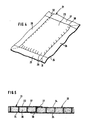
- the protective element (21) consists of two superimposed textile webs (23, 24). Both textile webs (23, 24) are designed as ribbon fabrics made of HDPE, a stabilizing coating ensuring that the textile webs (23, 24) are low-stretch and resistant to displacement.
- the two textile webs (23, 24) form overlap strips (25, 26, 27, 28) on all edges.
- the textile webs (23, 24) are interwoven with one another, while in the area of the overlap strips (25, 27) on the transverse side they have transverse seams (29, 30).
- the textile webs (23, 24) are arched apart and have an essentially constant distance of approximately 2.5 cm. The interior formed in this way is filled with sand with a grain size of 0 ⁇ to 3 mm.
- incisions (31, 32) are provided, which go from the outer edges of the transverse overlap strips (25, 27) to the transverse seams (29, 30 ⁇ ), namely in continuation of the inner edges of the longitudinal overlap strips (26, 28).
- incisions (31, 32) can also be provided, as indicated by dashed lines in the other two corners.
- This protective element (21) is produced in such a way that the textile webs (23, 24) are produced endlessly by tubular weaving and the longitudinal overlap strips (26, 28) are woven flat with one another. This textile tube is then cut through at appropriate intervals and the transverse seam (30 ⁇ ) is first sewn. The interior is then filled with the sand from the opening formed by the overlap strip (25) up to the height of the transverse seam (29). The opening there is then sewn directly adjacent to the fill level through the seam (29). Finally, the incisions (31, 32) are provided.
- the sectional view according to FIG. 5 shows - in each case partially - two protective elements (21, 33) placed next to one another.
- Both protective elements (21, 33) each consist of a top and a bottom textile web (23, 24) or (34, 35), which are essentially the same distance apart and filled with sand (36).
- the distance between the textile webs (23, 24) or (34, 35) is limited by delimiting ribbons - denoted by (37) for example. They were already woven in during the weaving process - initially at an angle - and when the sand (36) was filled in, they straightened up due to their displacement effect. The latter has the result that - in the exemplary embodiment according to FIG.
- the transverse overlap strip (27) is essentially flush with the Textile web (23) comes to rest, while the opposite overlap strip (25) lies flush with the underside textile web (24).
- the limiting tapes (35) ensure that the protective elements (21, 33) have the same height over the filling area of the sand (34), since they each have the same length.
- the protective elements (21, 33) are placed close together on their end faces.
- they are welded to the respective textile webs (24) or (34) by the action of hot air.
Landscapes
- Engineering & Computer Science (AREA)
- General Engineering & Computer Science (AREA)
- Environmental & Geological Engineering (AREA)
- Civil Engineering (AREA)
- Life Sciences & Earth Sciences (AREA)
- Structural Engineering (AREA)
- General Life Sciences & Earth Sciences (AREA)
- Paleontology (AREA)
- Mining & Mineral Resources (AREA)
- Hydrology & Water Resources (AREA)
- Ocean & Marine Engineering (AREA)
- Mechanical Engineering (AREA)
- Revetment (AREA)
- Packages (AREA)
- Processing Of Solid Wastes (AREA)
- Secondary Cells (AREA)
- Laminated Bodies (AREA)
Priority Applications (1)
| Application Number | Priority Date | Filing Date | Title |
|---|---|---|---|
| US08/066,441 US5423629A (en) | 1990-04-03 | 1993-05-25 | Protective element for protecting sealed tracks in trash-dump construction and method for sealing trash-dump bottoms |
Applications Claiming Priority (2)
| Application Number | Priority Date | Filing Date | Title |
|---|---|---|---|
| DE4010636 | 1990-04-03 | ||
| DE4010636 | 1990-04-03 |
Publications (2)
| Publication Number | Publication Date |
|---|---|
| EP0450154A1 true EP0450154A1 (fr) | 1991-10-09 |
| EP0450154B1 EP0450154B1 (fr) | 1994-03-23 |
Family
ID=6403617
Family Applications (1)
| Application Number | Title | Priority Date | Filing Date |
|---|---|---|---|
| EP90121719A Expired - Lifetime EP0450154B1 (fr) | 1990-04-03 | 1990-11-13 | Utilisation d'un element de protection pour la protection pour couches d'étanchéité de dépôts d'ordures et procédé pour rendre des dépôts d'ordures étanches |
Country Status (7)
| Country | Link |
|---|---|
| US (2) | US5215408A (fr) |
| EP (1) | EP0450154B1 (fr) |
| AT (1) | ATE103356T1 (fr) |
| CA (1) | CA2036355A1 (fr) |
| DE (1) | DE59005120D1 (fr) |
| DK (1) | DK0450154T3 (fr) |
| ES (1) | ES2053057T3 (fr) |
Cited By (3)
| Publication number | Priority date | Publication date | Assignee | Title |
|---|---|---|---|---|
| DE4133097A1 (de) * | 1991-10-05 | 1993-04-08 | Friedrich Geb | Fluessigkeitsdurchlaessige schutzmatte sowie verfahren zur herstellung derselben |
| EP0748900A1 (fr) * | 1995-06-12 | 1996-12-18 | Gebrüder Friedrich Gmbh | Procédé de fabrication de mats et dispositif de mise en oeuvre du procédé |
| DE29620102U1 (de) * | 1996-11-20 | 1997-01-09 | Gebrüder Friedrich GmbH, 38229 Salzgitter | Schutzmatte für den Wasserbau |
Families Citing this family (9)
| Publication number | Priority date | Publication date | Assignee | Title |
|---|---|---|---|---|
| US5765967A (en) * | 1996-05-01 | 1998-06-16 | Kni Incorporated | Method and apparatus for backfilling pipeline trenches |
| US5695443A (en) * | 1996-07-26 | 1997-12-09 | Brent; Robert W. | High energy radiation emission shelter and method of making the same |
| EP1256391B1 (fr) * | 2001-05-08 | 2004-09-22 | Ivan Rowe | Barriére hydraulique |
| US6973758B2 (en) | 2001-05-14 | 2005-12-13 | Rad Technology, Llc | Shielded structure for radiation treatment equipment and method of assembly |
| US6691472B2 (en) * | 2002-02-15 | 2004-02-17 | Theodore G. Hubert | Foundation wall protector |
| US7481024B1 (en) * | 2003-02-20 | 2009-01-27 | Geier Ralph H | Apparatus for placing soil into cells |
| GB0604169D0 (en) * | 2006-03-02 | 2006-04-12 | Jay Anthony | Track bed structures |
| JP6166200B2 (ja) * | 2014-03-12 | 2017-07-19 | 株式会社九コン | 土嚢袋及び土嚢並びに土嚢の設置方法 |
| CN108889759A (zh) * | 2018-06-02 | 2018-11-27 | 熊冠 | 一种乡村固态垃圾填埋设备 |
Citations (3)
| Publication number | Priority date | Publication date | Assignee | Title |
|---|---|---|---|---|
| BE560165A (fr) * | ||||
| US4572705A (en) * | 1978-11-14 | 1986-02-25 | Vignon Jean Francois B J | Revetment of cellular textile material |
| EP0274564A2 (fr) * | 1987-01-12 | 1988-07-20 | Hüls Troisdorf Aktiengesellschaft | Etanchement pour la constitution de décharges nouvelles |
Family Cites Families (27)
| Publication number | Priority date | Publication date | Assignee | Title |
|---|---|---|---|---|
| FR470998A (fr) * | 1913-04-18 | 1914-10-08 | Giulio Serrazanetti | Système de construction de gabionnades en réseau de fil de fer ou autre pour la défense des rivages de la mer, des fleuves, des canaux, des torrents, etc., pour servir de soutien contre les éboulements des terrains en pente et autres emplois semblables, et éléments ou membrures s'y rapportant |
| US3113435A (en) * | 1960-03-29 | 1963-12-10 | Stanley G Yount | Composite metal reinforced sheet means |
| GB935349A (en) * | 1960-10-28 | 1963-08-28 | Michael George Ionides | Layers for preventing or minimising fluid flow through surfaces and methods of making such layers |
| US3160512A (en) * | 1960-12-19 | 1964-12-08 | Flintkote Co | Material for lining canals and ditches |
| GB970805A (en) * | 1963-06-14 | 1964-09-23 | River & Sea Gabions Ltd | Improvements relating to protective linings for watercourses and other exposed surfaces |
| NL7212202A (fr) * | 1972-09-07 | 1974-03-11 | ||
| NO134124L (fr) * | 1972-09-15 | |||
| US4501788A (en) * | 1981-02-27 | 1985-02-26 | Clem Environmental Corp. | Waterproofing soil |
| NL8101171A (nl) * | 1981-03-11 | 1982-10-01 | Aannemers Comb Zinkwerke | Filtermatras. |
| DE3270401D1 (en) * | 1981-07-27 | 1986-05-15 | Tesch G H | Laminated article for construction purposes, and its application |
| US4483640A (en) * | 1981-09-09 | 1984-11-20 | Berger Robert C | Erosion control device |
| US4467015A (en) * | 1981-11-02 | 1984-08-21 | Clem Arthur G | Waterproofing structure |
| US4565468A (en) * | 1983-10-24 | 1986-01-21 | Crawford Leslie A | Moisture impervient barrier and method for making same |
| US4690585A (en) * | 1985-01-17 | 1987-09-01 | Holmberg Dick L | Erosion control foundation mat and method |
| JPH0723571B2 (ja) * | 1985-01-30 | 1995-03-15 | 旭化成工業株式会社 | 多層織物 |
| IT207068Z2 (it) * | 1985-12-17 | 1987-11-23 | Maccaferri Spa Off | Gabbione del tipo a materasso per realizzare strutture protettive di rivestimento da applicarsi alle superifici di terreni soggetti a erosione |
| DE3620388A1 (de) * | 1986-06-18 | 1987-12-23 | Akzo Gmbh | Draenmatte mit hoher druckbestaendigkeit |
| US4696599A (en) * | 1986-07-14 | 1987-09-29 | Waste Resource Associates, Inc. | Secure landfill and method of operating a landfill for hazardous waste |
| JPS63223223A (ja) * | 1987-03-12 | 1988-09-16 | Hiromi Hatanaka | ドレンネツトに緑化工を用いた法面保護工法 |
| SU1469008A1 (ru) * | 1987-04-23 | 1989-03-30 | Белорусский Научно-Исследовательский Институт Мелиорации И Водного Хозяйства | Защитное покрытие откоса |
| JPS6431727A (en) * | 1987-07-28 | 1989-02-02 | Mitsubishi Chem Ind | Dissolution of argininamide and drug composition containing argininamides |
| JPS6446022A (en) * | 1987-08-11 | 1989-02-20 | Honda Motor Co Ltd | Clutch device for working machine |
| JPS6446021A (en) * | 1987-08-14 | 1989-02-20 | K Seven Kk | Rotational force transmitting joint |
| JPH0254013A (ja) * | 1988-08-12 | 1990-02-23 | Kyoei Doboku Kogaku Kk | 遮水マットの施工方法 |
| US4943185A (en) * | 1989-03-03 | 1990-07-24 | Mcguckin James P | Combined drainage and waterproofing panel system for subterranean walls |
| US5000618A (en) * | 1989-04-06 | 1991-03-19 | Rohm And Haas Company | Method to prevent clogging of geotextiles and geonets |
| DE8906310U1 (de) * | 1989-05-22 | 1989-08-24 | Lutz, Hermann, 7404 Ofterdingen | Wand-Dämmplatte |
-
1990
- 1990-11-13 EP EP90121719A patent/EP0450154B1/fr not_active Expired - Lifetime
- 1990-11-13 AT AT90121719T patent/ATE103356T1/de not_active IP Right Cessation
- 1990-11-13 DK DK90121719.0T patent/DK0450154T3/da active
- 1990-11-13 DE DE90121719T patent/DE59005120D1/de not_active Expired - Fee Related
- 1990-11-13 ES ES90121719T patent/ES2053057T3/es not_active Expired - Lifetime
-
1991
- 1991-02-14 CA CA002036355A patent/CA2036355A1/fr not_active Abandoned
- 1991-04-03 US US07/679,905 patent/US5215408A/en not_active Expired - Fee Related
-
1993
- 1993-05-25 US US08/066,441 patent/US5423629A/en not_active Expired - Fee Related
Patent Citations (3)
| Publication number | Priority date | Publication date | Assignee | Title |
|---|---|---|---|---|
| BE560165A (fr) * | ||||
| US4572705A (en) * | 1978-11-14 | 1986-02-25 | Vignon Jean Francois B J | Revetment of cellular textile material |
| EP0274564A2 (fr) * | 1987-01-12 | 1988-07-20 | Hüls Troisdorf Aktiengesellschaft | Etanchement pour la constitution de décharges nouvelles |
Cited By (3)
| Publication number | Priority date | Publication date | Assignee | Title |
|---|---|---|---|---|
| DE4133097A1 (de) * | 1991-10-05 | 1993-04-08 | Friedrich Geb | Fluessigkeitsdurchlaessige schutzmatte sowie verfahren zur herstellung derselben |
| EP0748900A1 (fr) * | 1995-06-12 | 1996-12-18 | Gebrüder Friedrich Gmbh | Procédé de fabrication de mats et dispositif de mise en oeuvre du procédé |
| DE29620102U1 (de) * | 1996-11-20 | 1997-01-09 | Gebrüder Friedrich GmbH, 38229 Salzgitter | Schutzmatte für den Wasserbau |
Also Published As
| Publication number | Publication date |
|---|---|
| DE59005120D1 (de) | 1994-04-28 |
| DK0450154T3 (da) | 1994-07-18 |
| US5215408A (en) | 1993-06-01 |
| ATE103356T1 (de) | 1994-04-15 |
| EP0450154B1 (fr) | 1994-03-23 |
| CA2036355A1 (fr) | 1991-10-04 |
| US5423629A (en) | 1995-06-13 |
| ES2053057T3 (es) | 1994-07-16 |
Similar Documents
| Publication | Publication Date | Title |
|---|---|---|
| EP1088135B1 (fr) | Bande de tissu composite pour armer des couches de terre | |
| EP0450154B1 (fr) | Utilisation d'un element de protection pour la protection pour couches d'étanchéité de dépôts d'ordures et procédé pour rendre des dépôts d'ordures étanches | |
| DE3419163C2 (fr) | ||
| EP0536475A1 (fr) | Tapis d'étanchéité utilisable en génie civil pour la protection du sol contre des liquides | |
| DE69725563T2 (de) | Geo-verbundmembran | |
| DE9400650U1 (de) | Verbundmatte, insbesondere für den Fels-, Böschungs- und Deponiebau | |
| DE3632951A1 (de) | Flexible abdichtungsbahn | |
| EP0684343B1 (fr) | Procédé pour la fabrication de parois étanches | |
| EP2248722B1 (fr) | Unité d'emballage sans palette | |
| DE4405523A1 (de) | Schalungsmatte und Verfahren zur Herstellung eines mechanischen Schutzes | |
| DE4400183A1 (de) | Drän-Entwässerungselement für Abfalldeponien und sonstige Verwendung im Erd-, Grund- und Wasserbau | |
| EP1871958B1 (fr) | Materiau d'etancheification de construction | |
| DE4012301C2 (de) | Schalungshülle | |
| DE69419321T2 (de) | Abfallverarbeitung | |
| DE3523899C2 (de) | Dichtungselement | |
| DE4131743C2 (de) | Basisabdichtung für Mülldeponien | |
| DE19738169A1 (de) | Dichtungsmatte | |
| DE4109050C2 (de) | Dränmatte mit Sperrwirkung | |
| DE4133097A1 (de) | Fluessigkeitsdurchlaessige schutzmatte sowie verfahren zur herstellung derselben | |
| DE19808019A1 (de) | Abdichtbahn | |
| DE2054029C3 (de) | Dichtungsbahn aus Kunststoff | |
| DE68905951T2 (de) | Biegsame, wasserundurchlaessige platte. | |
| DE29515834U1 (de) | Abdichtmatte | |
| DE102024116627A1 (de) | Verfahren und Vorrichtung zur Vor-Ort-Herstellung eines Schutzdamms | |
| DE2221589C3 (de) | Verfahren und Vorrichtung zum Behandeln einer Kunststoffolie |
Legal Events
| Date | Code | Title | Description |
|---|---|---|---|
| PUAI | Public reference made under article 153(3) epc to a published international application that has entered the european phase |
Free format text: ORIGINAL CODE: 0009012 |
|
| AK | Designated contracting states |
Kind code of ref document: A1 Designated state(s): AT BE CH DE DK ES FR GB GR IT LI LU NL SE |
|
| 17P | Request for examination filed |
Effective date: 19920218 |
|
| 17Q | First examination report despatched |
Effective date: 19920402 |
|
| GRAA | (expected) grant |
Free format text: ORIGINAL CODE: 0009210 |
|
| AK | Designated contracting states |
Kind code of ref document: B1 Designated state(s): AT BE CH DE DK ES FR GB GR IT LI LU NL SE |
|
| REF | Corresponds to: |
Ref document number: 103356 Country of ref document: AT Date of ref document: 19940415 Kind code of ref document: T |
|
| REF | Corresponds to: |
Ref document number: 59005120 Country of ref document: DE Date of ref document: 19940428 |
|
| GBT | Gb: translation of ep patent filed (gb section 77(6)(a)/1977) |
Effective date: 19940518 |
|
| ITF | It: translation for a ep patent filed | ||
| REG | Reference to a national code |
Ref country code: ES Ref legal event code: FG2A Ref document number: 2053057 Country of ref document: ES Kind code of ref document: T3 |
|
| REG | Reference to a national code |
Ref country code: DK Ref legal event code: T3 |
|
| ET | Fr: translation filed | ||
| REG | Reference to a national code |
Ref country code: GR Ref legal event code: FG4A Free format text: 3012247 |
|
| PLBE | No opposition filed within time limit |
Free format text: ORIGINAL CODE: 0009261 |
|
| STAA | Information on the status of an ep patent application or granted ep patent |
Free format text: STATUS: NO OPPOSITION FILED WITHIN TIME LIMIT |
|
| EAL | Se: european patent in force in sweden |
Ref document number: 90121719.0 |
|
| 26N | No opposition filed | ||
| PGFP | Annual fee paid to national office [announced via postgrant information from national office to epo] |
Ref country code: GB Payment date: 19961024 Year of fee payment: 7 |
|
| PGFP | Annual fee paid to national office [announced via postgrant information from national office to epo] |
Ref country code: SE Payment date: 19961122 Year of fee payment: 7 |
|
| PGFP | Annual fee paid to national office [announced via postgrant information from national office to epo] |
Ref country code: DK Payment date: 19961125 Year of fee payment: 7 Ref country code: AT Payment date: 19961125 Year of fee payment: 7 |
|
| PGFP | Annual fee paid to national office [announced via postgrant information from national office to epo] |
Ref country code: CH Payment date: 19961126 Year of fee payment: 7 |
|
| PGFP | Annual fee paid to national office [announced via postgrant information from national office to epo] |
Ref country code: GR Payment date: 19961127 Year of fee payment: 7 |
|
| PGFP | Annual fee paid to national office [announced via postgrant information from national office to epo] |
Ref country code: ES Payment date: 19961129 Year of fee payment: 7 |
|
| PG25 | Lapsed in a contracting state [announced via postgrant information from national office to epo] |
Ref country code: GB Free format text: LAPSE BECAUSE OF NON-PAYMENT OF DUE FEES Effective date: 19971113 Ref country code: AT Free format text: LAPSE BECAUSE OF NON-PAYMENT OF DUE FEES Effective date: 19971113 |
|
| PG25 | Lapsed in a contracting state [announced via postgrant information from national office to epo] |
Ref country code: SE Free format text: LAPSE BECAUSE OF NON-PAYMENT OF DUE FEES Effective date: 19971114 Ref country code: ES Free format text: LAPSE BECAUSE OF NON-PAYMENT OF DUE FEES Effective date: 19971114 |
|
| PG25 | Lapsed in a contracting state [announced via postgrant information from national office to epo] |
Ref country code: LI Free format text: LAPSE BECAUSE OF NON-PAYMENT OF DUE FEES Effective date: 19971130 Ref country code: GR Free format text: LAPSE BECAUSE OF NON-PAYMENT OF DUE FEES Effective date: 19971130 Ref country code: CH Free format text: LAPSE BECAUSE OF NON-PAYMENT OF DUE FEES Effective date: 19971130 |
|
| PG25 | Lapsed in a contracting state [announced via postgrant information from national office to epo] |
Ref country code: DK Free format text: LAPSE BECAUSE OF NON-PAYMENT OF DUE FEES Effective date: 19971231 |
|
| GBPC | Gb: european patent ceased through non-payment of renewal fee |
Effective date: 19971113 |
|
| REG | Reference to a national code |
Ref country code: CH Ref legal event code: PL |
|
| EUG | Se: european patent has lapsed |
Ref document number: 90121719.0 |
|
| PGFP | Annual fee paid to national office [announced via postgrant information from national office to epo] |
Ref country code: DE Payment date: 19981118 Year of fee payment: 9 |
|
| PGFP | Annual fee paid to national office [announced via postgrant information from national office to epo] |
Ref country code: FR Payment date: 19981216 Year of fee payment: 9 |
|
| PGFP | Annual fee paid to national office [announced via postgrant information from national office to epo] |
Ref country code: BE Payment date: 19981222 Year of fee payment: 9 |
|
| PGFP | Annual fee paid to national office [announced via postgrant information from national office to epo] |
Ref country code: LU Payment date: 19981223 Year of fee payment: 9 |
|
| PGFP | Annual fee paid to national office [announced via postgrant information from national office to epo] |
Ref country code: NL Payment date: 19981231 Year of fee payment: 9 |
|
| PG25 | Lapsed in a contracting state [announced via postgrant information from national office to epo] |
Ref country code: LU Free format text: LAPSE BECAUSE OF NON-PAYMENT OF DUE FEES Effective date: 19991113 |
|
| PG25 | Lapsed in a contracting state [announced via postgrant information from national office to epo] |
Ref country code: BE Free format text: LAPSE BECAUSE OF NON-PAYMENT OF DUE FEES Effective date: 19991130 |
|
| BERE | Be: lapsed |
Owner name: GEBRUDER FRIEDRICH G.M.B.H. Effective date: 19991130 |
|
| PG25 | Lapsed in a contracting state [announced via postgrant information from national office to epo] |
Ref country code: NL Free format text: LAPSE BECAUSE OF NON-PAYMENT OF DUE FEES Effective date: 20000601 |
|
| PG25 | Lapsed in a contracting state [announced via postgrant information from national office to epo] |
Ref country code: FR Free format text: LAPSE BECAUSE OF NON-PAYMENT OF DUE FEES Effective date: 20000731 |
|
| NLV4 | Nl: lapsed or anulled due to non-payment of the annual fee |
Effective date: 20000601 |
|
| PG25 | Lapsed in a contracting state [announced via postgrant information from national office to epo] |
Ref country code: DE Free format text: LAPSE BECAUSE OF NON-PAYMENT OF DUE FEES Effective date: 20000901 |
|
| REG | Reference to a national code |
Ref country code: FR Ref legal event code: ST |
|
| REG | Reference to a national code |
Ref country code: ES Ref legal event code: FD2A Effective date: 20010503 |
|
| REG | Reference to a national code |
Ref country code: DK Ref legal event code: EBP |
|
| PG25 | Lapsed in a contracting state [announced via postgrant information from national office to epo] |
Ref country code: IT Free format text: LAPSE BECAUSE OF NON-PAYMENT OF DUE FEES Effective date: 20051113 |