EP0450190A1 - Fiche blindée pour la transmission des données - Google Patents
Fiche blindée pour la transmission des données Download PDFInfo
- Publication number
- EP0450190A1 EP0450190A1 EP90125398A EP90125398A EP0450190A1 EP 0450190 A1 EP0450190 A1 EP 0450190A1 EP 90125398 A EP90125398 A EP 90125398A EP 90125398 A EP90125398 A EP 90125398A EP 0450190 A1 EP0450190 A1 EP 0450190A1
- Authority
- EP
- European Patent Office
- Prior art keywords
- contact
- module
- electrical connector
- connector according
- shielded electrical
- Prior art date
- Legal status (The legal status is an assumption and is not a legal conclusion. Google has not performed a legal analysis and makes no representation as to the accuracy of the status listed.)
- Granted
Links
- 230000005540 biological transmission Effects 0.000 title claims description 4
- 210000002105 tongue Anatomy 0.000 claims abstract description 9
- 239000004020 conductor Substances 0.000 claims description 8
- 239000011324 bead Substances 0.000 claims description 3
- 239000002184 metal Substances 0.000 abstract description 4
- 238000012216 screening Methods 0.000 abstract 4
- 238000010276 construction Methods 0.000 description 1
- 230000007613 environmental effect Effects 0.000 description 1
- 238000007654 immersion Methods 0.000 description 1
- 238000003908 quality control method Methods 0.000 description 1
- 238000013024 troubleshooting Methods 0.000 description 1
Images


Classifications
-
- H—ELECTRICITY
- H01—ELECTRIC ELEMENTS
- H01R—ELECTRICALLY-CONDUCTIVE CONNECTIONS; STRUCTURAL ASSOCIATIONS OF A PLURALITY OF MUTUALLY-INSULATED ELECTRICAL CONNECTING ELEMENTS; COUPLING DEVICES; CURRENT COLLECTORS
- H01R29/00—Coupling parts for selective co-operation with a counterpart in different ways to establish different circuits, e.g. for voltage selection, for series-parallel selection, programmable connectors
-
- H—ELECTRICITY
- H01—ELECTRIC ELEMENTS
- H01R—ELECTRICALLY-CONDUCTIVE CONNECTIONS; STRUCTURAL ASSOCIATIONS OF A PLURALITY OF MUTUALLY-INSULATED ELECTRICAL CONNECTING ELEMENTS; COUPLING DEVICES; CURRENT COLLECTORS
- H01R13/00—Details of coupling devices of the kinds covered by groups H01R12/70 or H01R24/00 - H01R33/00
- H01R13/648—Protective earth or shield arrangements on coupling devices, e.g. anti-static shielding
- H01R13/658—High frequency shielding arrangements, e.g. against EMI [Electro-Magnetic Interference] or EMP [Electro-Magnetic Pulse]
- H01R13/6591—Specific features or arrangements of connection of shield to conductive members
- H01R13/6592—Specific features or arrangements of connection of shield to conductive members the conductive member being a shielded cable
-
- H—ELECTRICITY
- H01—ELECTRIC ELEMENTS
- H01R—ELECTRICALLY-CONDUCTIVE CONNECTIONS; STRUCTURAL ASSOCIATIONS OF A PLURALITY OF MUTUALLY-INSULATED ELECTRICAL CONNECTING ELEMENTS; COUPLING DEVICES; CURRENT COLLECTORS
- H01R24/00—Two-part coupling devices, or either of their cooperating parts, characterised by their overall structure
- H01R24/84—Hermaphroditic coupling devices
Definitions
- the invention relates to a shielded electrical connector for data transmission with an insulating housing consisting of a lower cover, a contact module and an upper cover, with a shield extending from the cable entry area to the plug-in area, with a contact set arranged on a contact carrier, with a connection between Data conductors and contacts of the contact pack producing contact set and with a bridging device for establishing connections between certain contacts serving as line termination.
- an electrical connector for data communication applications which has an insulating housing consisting of a lower cover, a contact carrier and an upper cover with a shield extending from the cable entry area to the plug area.
- a one-piece screen element arranged on the upper cover is formed over the entire area in the cable entry area and is fork-shaped in the plug-in area.
- a one-piece screen element arranged on the lower cover has flanges forming cable entry openings in the cable entry area and ends in the plug-in area with a stepped fork.
- Data conductors are pressed into long slots arranged on contact sleeves by means of a contact pack.
- Two metal bridging rails arranged one behind the other on the contact carrier run transversely over resilient contact ends.
- Contact-side contact tabs of the one bridging rail are offset in the transverse direction with respect to contact tabs of the other bridging rail, so that the one bridging rail is connected to the one contact end and the other Bridging rail is in connection with the other contact ends.
- the contact ends are separated from the bridging rails.
- a disadvantage of the known device is that neither a user-friendly cable assembly nor a perfect cable entry termination is possible with the screen elements used.
- Another disadvantage is that, if installed incorrectly, the bridging rails may meet the upper shield element and produce undesired connections, which can lead to lengthy troubleshooting.
- the bridging rails are exposed to environmental influences without protection, which means that contact problems are inevitable.
- the invention seeks to remedy this.
- the invention as characterized in the claims, solves the problem of improving the cable entry area of a data connector in such a way that the connector shield can be adapted without tools in the event of changes to the cable entry and to improve the bridging device serving as a line termination so that the data conductors to be connected can be freely selected.
- the advantages achieved by the invention are essentially to be seen in the fact that changes in existing networks can be made effortlessly with the connector according to the invention, that even if the connector is assembled incorrectly, no connections can occur between the connector contacts and the shielding and that the connector can be checked at any time during quality control, before and after cable assembly and after merging with another hermaphroditic connector.
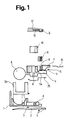
- 1 denotes a lower cover made of plastic, on which an articulation 3 supporting an arm 2 engages.
- a snap tongue 4 is provided on the arm 2 on the plug side.
- the lower cover 1 is locked in place A with a contact module 5 made of plastic, which has a contact carrier 6 and, on the plug side, a hood 7 arranged above the contact carrier 6 and covers 8 which can be removed on the cable side.
- the contact carrier 6 is prepared for accommodating a contact set consisting of several contacts 9 with an associated contact pack 10 and for accommodating an encodable bridge module 11.
- the plug according to the invention is closed at the top with an upper cover 12 made of plastic, which latches with the contact module 5 at point B with the hood 7 and at other points (not shown), which has the same elements required for latching with another hermaphroditic plug as the lower cover 1.
- the upper cover shield consists of an upper shield element 13 and a first and second shield tongue 14; 15 with ends 16 bent open on the plug side and with V-shaped crankings 17 on the bridge module side.
- the shield tongues 14; which produce the shield contact with other hermaphroditic plugs; 15 are inserted under the hood 7 and inserted into dovetail-like guides 18 of the bridge module 11 arranged on the bridge module 11 until their V-shaped crankings 17 snap into V-shaped grooves 19 lying transversely to the dovetail-like guides 18.
- the upper shield element 13 fastened to the upper cover 12 has contact tabs 20 with recesses 21 on the cable side and a downwardly bent front side 22 on the bridge module side which, when the upper cover 12 is put on, with the V-shaped crankings 17 of the shield tongues 14; 15 click into place.
- the latching and ensuring the shield contact between the upper shield element 13 and the shield tongues 14; 15 necessary force generated by the spring action of the front part 24 set off from the upper cover 12 by means of a step 23.
- an upper cover 12 and an upper shielding element 13 are provided with means for vertical cable entry.
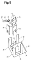
- the lower cover shield consists of a forked lower shield element 25 arranged on the plug side and a shield module 26 arranged on the cable side.
- the lower shield element 25, which makes shield contact with another hermaphroditic connector, has a step-like forked front part 27, an end 28 that is cranked on the shield module side, and openings 29 and latches 30 on, which are pressed into the lower surface of the contact carrier 6.
- the shield module 26 consists of a rectangular base plate 31 arranged on the inner surface of the lower cover 1, on the side of the contact carrier on which a bead 32 is formed. On the other sides of the base plate 31, module walls 33 are provided with wall openings 34 and guide tabs 35 pointing inwards in the lower wall area.
- the resilient cranked end 28 of the lower shield element 25 is pressed onto the bead 32 of the base plate 31, thereby ensuring reliable shield contact between the lower shield element 25 and the shield module 26.
- Double-walled spring walls 36 serving as closure of the wall openings 34 are pluggable onto the module walls 33, so that a cage which is shielded on four sides against electromagnetic influences is produced.
- the cables 37 used for data transmission have data conductors 38 which are encased in a braided shield 39.
- the screen braid 39 is placed over a metal end sleeve 40 which is attached to the ends of the cable and is inserted into a spring wall 36 with guide tabs 35 provided as a cable bushing.
- the guide tabs 35 of the spring wall 36 when the spring wall 36 is plugged onto a module wall 33, form with the guide tab 35 of the module wall 33 a holder that encompasses the widened ends of the end sleeve 40 on all sides to relieve the cable conductors 38 of tensile and compressive stresses.
- Contact tabs 41 are provided at the upper end of the spring walls 36, which snap into the recesses 21 of the contact tabs 20 of the upper shield element 13 when the upper cover 12 is put on.
- the removable covers 8 of the contact module 5 are removed depending on the cable entries.
- the guide tabs 35 of the spring wall 36 are designed in such a way that end sleeves for flat cables are held.
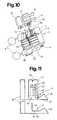
- the bridge module 11 has two horizontal passages 42, which run at the same height and run parallel and over the entire width, for receiving one metallic pin 43 each.
- a cubic recess 44 is provided for each contact 9, which with the contact carrier 6 has an opening for the free passage of a contact rail 45 and for the free immersion of a contact end 46 of the contact 9.
- two vertical passages 47 which run from the cutout 44 and are located one behind the other and lead to a horizontal passage 42, are provided. The clear diameter of the vertical passage 47 is selected so that metallic bolts 48 can move freely in the vertical direction.
- a bolt 48 is inserted into one of the two vertical passages 47 during assembly of the plug 9 and pressed by the spring action of the contact end 46 against the pin 43, thus connecting to the other contacts 9 of the contact set achievable horizontal pins 43 is made. If the connector is merged with another hermaphroditic connector, the force acting on a contact area 49 of the contact 9 causes the free contact end 46 to move downward.
- the bolt 48 which is freely movable in the vertical passage 47, follows the movement of the contact end 46, as a result of which the electrical connection to the pin 43 is interrupted.
- contacts 9 with contact ends 46 of different lengths are used.
- two guide strips 50 with a rectangular cross section are provided, which engage in rectangular guide grooves 52 arranged on the side walls 51 of the contact module 5.
- a contact guide groove 53 is provided with a snap groove (not shown) for fixing the contact 9.
- Contact sleeves 54 arranged at right angles to the contact rails 45 have long slots (not shown on the cable side) for receiving the data conductors 38, into which the conductors are pressed by means of the plastic contact pack 10 guided on the side walls 51 of the contact module 5.
Landscapes
- Details Of Connecting Devices For Male And Female Coupling (AREA)
- Coupling Device And Connection With Printed Circuit (AREA)
- Communication Cables (AREA)
- Connections Arranged To Contact A Plurality Of Conductors (AREA)
- Connections By Means Of Piercing Elements, Nuts, Or Screws (AREA)
Applications Claiming Priority (2)
| Application Number | Priority Date | Filing Date | Title |
|---|---|---|---|
| CH1128/90 | 1990-04-04 | ||
| CH112890 | 1990-04-04 |
Publications (2)
| Publication Number | Publication Date |
|---|---|
| EP0450190A1 true EP0450190A1 (fr) | 1991-10-09 |
| EP0450190B1 EP0450190B1 (fr) | 1995-03-01 |
Family
ID=4203146
Family Applications (1)
| Application Number | Title | Priority Date | Filing Date |
|---|---|---|---|
| EP90125398A Expired - Lifetime EP0450190B1 (fr) | 1990-04-04 | 1990-12-24 | Fiche blindée pour la transmission des données |
Country Status (3)
| Country | Link |
|---|---|
| EP (1) | EP0450190B1 (fr) |
| AT (1) | ATE119325T1 (fr) |
| DE (1) | DE59008598D1 (fr) |
Cited By (1)
| Publication number | Priority date | Publication date | Assignee | Title |
|---|---|---|---|---|
| DE4331143C1 (de) * | 1993-09-14 | 1995-02-02 | Gaertner Karl Telegaertner | Anschlußdose zur Bildung einer Anschlußeinrichtung für ein Datennetz |
Citations (4)
| Publication number | Priority date | Publication date | Assignee | Title |
|---|---|---|---|---|
| EP0079016A1 (fr) * | 1981-11-10 | 1983-05-18 | HARTING ELEKTRONIK GmbH | Connexion enfichable avec pont de contact interrupteur |
| EP0112711A1 (fr) * | 1982-12-22 | 1984-07-04 | AMP INCORPORATED (a New Jersey corporation) | Connecteur électrique protégé par un shunt |
| EP0158531A2 (fr) * | 1984-04-09 | 1985-10-16 | The Whitaker Corporation | Connecteur électrique et rail de court-circuit à effet frottant |
| EP0219304A1 (fr) * | 1985-10-07 | 1987-04-22 | Thomas & Betts Corporation | Connecteur électrique et pièce terminale de câble pour celui-ci |
-
1990
- 1990-12-24 DE DE59008598T patent/DE59008598D1/de not_active Expired - Fee Related
- 1990-12-24 AT AT90125398T patent/ATE119325T1/de not_active IP Right Cessation
- 1990-12-24 EP EP90125398A patent/EP0450190B1/fr not_active Expired - Lifetime
Patent Citations (4)
| Publication number | Priority date | Publication date | Assignee | Title |
|---|---|---|---|---|
| EP0079016A1 (fr) * | 1981-11-10 | 1983-05-18 | HARTING ELEKTRONIK GmbH | Connexion enfichable avec pont de contact interrupteur |
| EP0112711A1 (fr) * | 1982-12-22 | 1984-07-04 | AMP INCORPORATED (a New Jersey corporation) | Connecteur électrique protégé par un shunt |
| EP0158531A2 (fr) * | 1984-04-09 | 1985-10-16 | The Whitaker Corporation | Connecteur électrique et rail de court-circuit à effet frottant |
| EP0219304A1 (fr) * | 1985-10-07 | 1987-04-22 | Thomas & Betts Corporation | Connecteur électrique et pièce terminale de câble pour celui-ci |
Cited By (2)
| Publication number | Priority date | Publication date | Assignee | Title |
|---|---|---|---|---|
| DE4331143C1 (de) * | 1993-09-14 | 1995-02-02 | Gaertner Karl Telegaertner | Anschlußdose zur Bildung einer Anschlußeinrichtung für ein Datennetz |
| DE4345217A1 (de) * | 1993-09-14 | 1995-03-16 | Gaertner Karl Telegaertner | Anschlußkabel zur Bildung einer Anschlußeinrichtung für ein Datennetz |
Also Published As
| Publication number | Publication date |
|---|---|
| ATE119325T1 (de) | 1995-03-15 |
| DE59008598D1 (de) | 1995-04-06 |
| EP0450190B1 (fr) | 1995-03-01 |
Similar Documents
| Publication | Publication Date | Title |
|---|---|---|
| DE69218852T2 (de) | Verbinder zum Verbinden von zwei Koaxialkabeln mit einander | |
| DE102017008995B4 (de) | Verbinder | |
| DE3686879T2 (de) | Elektrischer verbinder und rastvorrichtung dafuer. | |
| DE69735414T2 (de) | Modulare steckdose mit verringertem übersprechen | |
| DE3650244T2 (de) | Klinkensteckvorrichtung. | |
| DE3650367T2 (de) | Abgeschirmter elektrischer Verbinder. | |
| DE69836510T2 (de) | Nachrichtenstecker | |
| DE3686859T2 (de) | Elektrischer verbinder und kabelendverschlussvorrichtung dafuer. | |
| DE4013189C2 (de) | Elektrische Steckverbindungsvorrichtung | |
| DE2807366A1 (de) | Verbinderanordnung | |
| DE8336870U1 (de) | Elektrischer Verbinder | |
| DE3750547T2 (de) | Abgeschirmter datenverbinder. | |
| DE3537722C2 (fr) | ||
| DE69321683T2 (de) | Abgeschirmter Verbinder zur Datenübertragung | |
| WO2007019974A1 (fr) | Element de connexion muni d'un boitier pour cables de telecommunications et/ou cables de donnees | |
| EP0379662A2 (fr) | Boîtier de prises | |
| EP0691040B1 (fr) | Connecteur multiple a passage de cable | |
| DE69112723T2 (de) | Kanaleinrichtung für Kabel und Leiter und Steckdosen, die damit verbunden werden. | |
| EP0450190B1 (fr) | Fiche blindée pour la transmission des données | |
| DE19532623A1 (de) | Elektrischer Stecker mit einem Betätigungsschieber | |
| EP0926790A2 (fr) | Adaptateur avec un boítier de base pour un jeu de barres omnibus avec plusieurs barres de distribution de courant | |
| DE19608876C2 (de) | Geschirmte Anschlußdose | |
| EP0951104B1 (fr) | Prise, particulièrement un boítier encastrable pour installations électriques | |
| EP0669045B1 (fr) | Dispositif de raccordement d'equipements electroniques | |
| CH715071B1 (de) | Verbrauchszähler mit Leiteranschlussvorrichtung. |
Legal Events
| Date | Code | Title | Description |
|---|---|---|---|
| PUAI | Public reference made under article 153(3) epc to a published international application that has entered the european phase |
Free format text: ORIGINAL CODE: 0009012 |
|
| AK | Designated contracting states |
Kind code of ref document: A1 Designated state(s): AT BE CH DE DK ES FR GB GR IT LI LU NL SE |
|
| 17P | Request for examination filed |
Effective date: 19920401 |
|
| 17Q | First examination report despatched |
Effective date: 19940124 |
|
| GRAA | (expected) grant |
Free format text: ORIGINAL CODE: 0009210 |
|
| AK | Designated contracting states |
Kind code of ref document: B1 Designated state(s): AT BE CH DE DK ES FR GB GR IT LI LU NL SE |
|
| PG25 | Lapsed in a contracting state [announced via postgrant information from national office to epo] |
Ref country code: IT Free format text: LAPSE BECAUSE OF FAILURE TO SUBMIT A TRANSLATION OF THE DESCRIPTION OR TO PAY THE FEE WITHIN THE PRE;WARNING: LAPSES OF ITALIAN PATENTS WITH EFFECTIVE DATE BEFORE 2007 MAY HAVE OCCURRED AT ANY TIME BEFORE 2007. THE CORRECT EFFECTIVE DATE MAY BE DIFFERENT FROM THE ONE RECORDED.SCRIBED TIME-LIMIT Effective date: 19950301 Ref country code: GR Free format text: LAPSE BECAUSE OF FAILURE TO SUBMIT A TRANSLATION OF THE DESCRIPTION OR TO PAY THE FEE WITHIN THE PRESCRIBED TIME-LIMIT Effective date: 19950301 Ref country code: GB Effective date: 19950301 Ref country code: DK Effective date: 19950301 Ref country code: ES Free format text: THE PATENT HAS BEEN ANNULLED BY A DECISION OF A NATIONAL AUTHORITY Effective date: 19950301 Ref country code: FR Effective date: 19950301 Ref country code: NL Free format text: LAPSE BECAUSE OF NON-PAYMENT OF DUE FEES Effective date: 19950301 Ref country code: BE Effective date: 19950301 |
|
| REF | Corresponds to: |
Ref document number: 119325 Country of ref document: AT Date of ref document: 19950315 Kind code of ref document: T |
|
| REF | Corresponds to: |
Ref document number: 59008598 Country of ref document: DE Date of ref document: 19950406 |
|
| PG25 | Lapsed in a contracting state [announced via postgrant information from national office to epo] |
Ref country code: SE Effective date: 19950601 |
|
| EN | Fr: translation not filed | ||
| NLV1 | Nl: lapsed or annulled due to failure to fulfill the requirements of art. 29p and 29m of the patents act | ||
| GBV | Gb: ep patent (uk) treated as always having been void in accordance with gb section 77(7)/1977 [no translation filed] |
Effective date: 19950301 |
|
| PG25 | Lapsed in a contracting state [announced via postgrant information from national office to epo] |
Ref country code: AT Effective date: 19951224 |
|
| PG25 | Lapsed in a contracting state [announced via postgrant information from national office to epo] |
Ref country code: LU Free format text: LAPSE BECAUSE OF NON-PAYMENT OF DUE FEES Effective date: 19951231 |
|
| PLBE | No opposition filed within time limit |
Free format text: ORIGINAL CODE: 0009261 |
|
| STAA | Information on the status of an ep patent application or granted ep patent |
Free format text: STATUS: NO OPPOSITION FILED WITHIN TIME LIMIT |
|
| 26N | No opposition filed | ||
| PGFP | Annual fee paid to national office [announced via postgrant information from national office to epo] |
Ref country code: DE Payment date: 19971119 Year of fee payment: 8 |
|
| PG25 | Lapsed in a contracting state [announced via postgrant information from national office to epo] |
Ref country code: DE Free format text: LAPSE BECAUSE OF NON-PAYMENT OF DUE FEES Effective date: 19991001 |
|
| PGFP | Annual fee paid to national office [announced via postgrant information from national office to epo] |
Ref country code: CH Payment date: 20010319 Year of fee payment: 11 |
|
| PG25 | Lapsed in a contracting state [announced via postgrant information from national office to epo] |
Ref country code: LI Free format text: LAPSE BECAUSE OF NON-PAYMENT OF DUE FEES Effective date: 20011231 Ref country code: CH Free format text: LAPSE BECAUSE OF NON-PAYMENT OF DUE FEES Effective date: 20011231 |
|
| REG | Reference to a national code |
Ref country code: CH Ref legal event code: PL |