EP0450477A2 - Doseur - Google Patents
Doseur Download PDFInfo
- Publication number
- EP0450477A2 EP0450477A2 EP91104841A EP91104841A EP0450477A2 EP 0450477 A2 EP0450477 A2 EP 0450477A2 EP 91104841 A EP91104841 A EP 91104841A EP 91104841 A EP91104841 A EP 91104841A EP 0450477 A2 EP0450477 A2 EP 0450477A2
- Authority
- EP
- European Patent Office
- Prior art keywords
- filling
- channel
- dosing device
- dosing
- rotational position
- Prior art date
- Legal status (The legal status is an assumption and is not a legal conclusion. Google has not performed a legal analysis and makes no representation as to the accuracy of the status listed.)
- Granted
Links
- 238000004140 cleaning Methods 0.000 claims abstract description 23
- 235000013361 beverage Nutrition 0.000 claims abstract description 3
- 238000003860 storage Methods 0.000 claims description 40
- 239000007788 liquid Substances 0.000 claims description 20
- 239000000654 additive Substances 0.000 claims description 19
- 239000003599 detergent Substances 0.000 claims description 15
- 230000000996 additive effect Effects 0.000 claims description 14
- 239000012530 fluid Substances 0.000 claims description 13
- 230000008878 coupling Effects 0.000 claims description 4
- 238000010168 coupling process Methods 0.000 claims description 4
- 238000005859 coupling reaction Methods 0.000 claims description 4
- 238000009423 ventilation Methods 0.000 claims description 4
- 239000012780 transparent material Substances 0.000 claims description 3
- 238000011144 upstream manufacturing Methods 0.000 claims description 2
- 239000003795 chemical substances by application Substances 0.000 description 13
- 238000000034 method Methods 0.000 description 7
- 238000007789 sealing Methods 0.000 description 7
- 239000012459 cleaning agent Substances 0.000 description 4
- XLYOFNOQVPJJNP-UHFFFAOYSA-N water Substances O XLYOFNOQVPJJNP-UHFFFAOYSA-N 0.000 description 4
- 230000002349 favourable effect Effects 0.000 description 3
- 229920003229 poly(methyl methacrylate) Polymers 0.000 description 3
- 239000004926 polymethyl methacrylate Substances 0.000 description 3
- IJGRMHOSHXDMSA-UHFFFAOYSA-N Atomic nitrogen Chemical compound N#N IJGRMHOSHXDMSA-UHFFFAOYSA-N 0.000 description 2
- 238000010276 construction Methods 0.000 description 2
- 238000011109 contamination Methods 0.000 description 2
- 239000000645 desinfectant Substances 0.000 description 2
- 238000010586 diagram Methods 0.000 description 2
- 238000005429 filling process Methods 0.000 description 2
- 239000007789 gas Substances 0.000 description 2
- 238000004519 manufacturing process Methods 0.000 description 2
- CURLTUGMZLYLDI-UHFFFAOYSA-N Carbon dioxide Chemical compound O=C=O CURLTUGMZLYLDI-UHFFFAOYSA-N 0.000 description 1
- 208000009043 Chemical Burns Diseases 0.000 description 1
- 208000027418 Wounds and injury Diseases 0.000 description 1
- 239000002253 acid Substances 0.000 description 1
- 150000007513 acids Chemical class 0.000 description 1
- BVKZGUZCCUSVTD-UHFFFAOYSA-N carbonic acid Chemical compound OC(O)=O BVKZGUZCCUSVTD-UHFFFAOYSA-N 0.000 description 1
- 230000006378 damage Effects 0.000 description 1
- 230000001419 dependent effect Effects 0.000 description 1
- 238000006073 displacement reaction Methods 0.000 description 1
- 230000000694 effects Effects 0.000 description 1
- 239000000314 lubricant Substances 0.000 description 1
- 239000000463 material Substances 0.000 description 1
- 229910052757 nitrogen Inorganic materials 0.000 description 1
- 230000002093 peripheral effect Effects 0.000 description 1
- 239000004033 plastic Substances 0.000 description 1
- 229920003023 plastic Polymers 0.000 description 1
- 239000000344 soap Substances 0.000 description 1
- 239000007787 solid Substances 0.000 description 1
- 239000000126 substance Substances 0.000 description 1
- 238000005406 washing Methods 0.000 description 1
Images




Classifications
-
- B—PERFORMING OPERATIONS; TRANSPORTING
- B08—CLEANING
- B08B—CLEANING IN GENERAL; PREVENTION OF FOULING IN GENERAL
- B08B9/00—Cleaning hollow articles by methods or apparatus specially adapted thereto
- B08B9/02—Cleaning pipes or tubes or systems of pipes or tubes
- B08B9/027—Cleaning the internal surfaces; Removal of blockages
- B08B9/032—Cleaning the internal surfaces; Removal of blockages by the mechanical action of a moving fluid, e.g. by flushing
-
- B—PERFORMING OPERATIONS; TRANSPORTING
- B08—CLEANING
- B08B—CLEANING IN GENERAL; PREVENTION OF FOULING IN GENERAL
- B08B9/00—Cleaning hollow articles by methods or apparatus specially adapted thereto
- B08B9/02—Cleaning pipes or tubes or systems of pipes or tubes
- B08B9/027—Cleaning the internal surfaces; Removal of blockages
- B08B9/032—Cleaning the internal surfaces; Removal of blockages by the mechanical action of a moving fluid, e.g. by flushing
- B08B9/0321—Cleaning the internal surfaces; Removal of blockages by the mechanical action of a moving fluid, e.g. by flushing using pressurised, pulsating or purging fluid
- B08B9/0327—Cleaning the internal surfaces; Removal of blockages by the mechanical action of a moving fluid, e.g. by flushing using pressurised, pulsating or purging fluid the fluid being in the form of a mist
-
- Y—GENERAL TAGGING OF NEW TECHNOLOGICAL DEVELOPMENTS; GENERAL TAGGING OF CROSS-SECTIONAL TECHNOLOGIES SPANNING OVER SEVERAL SECTIONS OF THE IPC; TECHNICAL SUBJECTS COVERED BY FORMER USPC CROSS-REFERENCE ART COLLECTIONS [XRACs] AND DIGESTS
- Y10—TECHNICAL SUBJECTS COVERED BY FORMER USPC
- Y10T—TECHNICAL SUBJECTS COVERED BY FORMER US CLASSIFICATION
- Y10T137/00—Fluid handling
- Y10T137/2496—Self-proportioning or correlating systems
- Y10T137/2514—Self-proportioning flow systems
- Y10T137/2521—Flow comparison or differential response
- Y10T137/2526—Main line flow displaces or entrains material from reservoir
-
- Y—GENERAL TAGGING OF NEW TECHNOLOGICAL DEVELOPMENTS; GENERAL TAGGING OF CROSS-SECTIONAL TECHNOLOGIES SPANNING OVER SEVERAL SECTIONS OF THE IPC; TECHNICAL SUBJECTS COVERED BY FORMER USPC CROSS-REFERENCE ART COLLECTIONS [XRACs] AND DIGESTS
- Y10—TECHNICAL SUBJECTS COVERED BY FORMER USPC
- Y10T—TECHNICAL SUBJECTS COVERED BY FORMER US CLASSIFICATION
- Y10T137/00—Fluid handling
- Y10T137/8593—Systems
- Y10T137/8597—Main line as motive fluid for follower-type feeder
Definitions
- the invention relates to a metering device with a filling cylinder which can be filled from a storage container via a closable refill channel and can be emptied via a metering channel by means of a displaceable piston.
- the dosing device is particularly suitable for a device for cleaning pipelines, such as beverage lines, with a cleaning liquid, to which a cleaning agent additive from the dosing device can be admixed.
- Usual cleaning liquids are alkalis, acids, disinfectant solutions or simply water, which is taken from a domestic water connection, for example.
- Detergent additives are additives in solid, liquid or gaseous form that are added to the cleaning liquids.
- a metering device of the type described in the introduction which is used in connection with a cleaning device for pipelines, is known from DE-PS 33 20 293.
- the connection opening can be closed by a valve. If this leaks due to contamination, the dosing agent flows continuously into the filling cylinder. An actuator for the valve is not shown.
- the storage container has to be refilled from transport containers from time to time, which often leads to contamination and, in the case of aggressive media, also to injuries to the operator.
- the known metering device is connected to a connection device for the pipes of the four-way switch valve to be cleaned.
- the four-way switch valve is designed so that it connects the supply line alternately with one of the connection devices and the drain line in each case with the other connection device, the switchover taking place under the influence of cleaning bodies.
- the effect of the metered detergent additives is limited and uneven.
- the invention is based on the object of specifying a metering device of the type described at the outset which enables very convenient handling and ensures that no metering agent gets into the filling cylinder when the filling channel is closed.
- a filling device which, together with the storage container, can be rotated about an approximately horizontal axis and releases the filling channel in a first rotational position, in which the storage container has an upper position, and in a second rotating position, in which the storage container is one takes the lower layer, closes.
- the filling device forms a filling valve. If it is swiveled up to the "fill” position, the fill valve opens and the dosing agent runs from the storage container into the interior of the filling cylinder. After the filling process, the filling device is turned down to the "close” position so that the filling valve closes again. In this position, the entire dosing agent is below the filling cylinder; unwanted dripping is therefore not possible.
- the rotatable filling device has a certain size because of its connection to the storage container and can therefore be easily adjusted by hand.
- the filling device can be rotatable about the axis of the filling cylinder.
- the filling cylinder therefore forms the supporting part of the filling device, so that a compact apparatus results.
- the filling device is of such a size that it can take on further valve functions.
- the filling device closes the metering channel in the first rotational position and releases it in the second rotational position. This ensures that no dosing agent flows through the dosing channel during filling.
- a check valve closing towards the filling cylinder or the storage container is provided in the metering channel and / or in the filling channel.
- the check valve prevents excessive pressure in the feed line or in the filling cylinder, e.g. due to incorrect actuation of the piston, undesirably affects the storage container.
- the filling device has a reservoir ventilation channel which is closed in the first rotational position and released in the second rotational position or an intermediate rotational position. In this way, the pressure in the reservoir can be reduced to atmospheric pressure.
- the filling device has a socket on which at least one connection for mechanical connection to the storage container is arranged.
- This connection is located in the cylinder wall of the socket.
- the storage container can therefore be connected directly to the filling device.
- Conventional transport bottles come into consideration as storage containers. In this way, the operating personnel does not come into contact with the dosing agent, which considerably increases the safety of handling the device. A risk of chemical burns is completely excluded.
- the storage container serves as a turning handle for the filling valve.
- the device has a plurality of connection connections, different containers with different dosing liquids, for example a container with lye and another container with disinfectant solution in the case of detergent additives, can be connected to the dosing device. Then only the corresponding container of the desired detergent additive has to be turned to the "fill" position during the dosing process.
- different containers with different dosing liquids for example a container with lye and another container with disinfectant solution in the case of detergent additives
- connection connections For example, threads, swivel couplings, bayonet locks or safety locks can be used as connection connections.
- the type of connection connection ultimately depends on the type of storage container of the dosing agent used. For example, these can be commercially available bottles.
- connection can be replaced. Since the filling holder with its specific connection connection is designed to be exchangeable, there is a high degree of adaptability to the storage container used in each case.
- the connection can for example be designed as a cylindrical socket with an internal thread on the outer wall of the socket.
- connection has a securing element for fastening the storage container.
- This securing element can be, for example, a union nut which is arranged on a flange of the connection and is connected to the external thread of the storage container.
- resilient clip elements are used as securing elements, which, with one end attached to the connection, encompass the storage container.
- the filling cylinder has a first opening, which is connected to the filling chamber, and an axially offset second opening, which is connected to the metering channel, and the filling device, a bushing, in the inner wall of which there is an axial groove Connection of the two openings and offset by an angle of approximately 180 ° thereto and the mouth of the filling channel is arranged in the cross-sectional plane of the first opening.
- the filling cylinder has a first control opening connected to its filling chamber and the filling device a second control opening which is connected to the filling channel and which cooperates with the first control opening in the first rotational position, a third control opening offset by approximately 180 °, which is connected to the first section of the metering channel and cooperates with the first control opening in the second rotational position, and has a fourth control opening located at the end of this first section, which is formed on the end face of the filling device and is covered by the end face of a holder, however cooperates in the second rotational position with a fifth control opening located in this end face, which is connected to a second section of the metering channel.
- valves formed by the control openings are distributed over the inner circumferential surface and the end face of the filling device, which offers great freedom in construction.
- all channels run outside the filling cylinder, so that it can be used as a filling space over its entire length.
- a sixth control opening is provided on the end face of the filling device, which is connected to the filling channel and, in a rotational position deviating from the first rotational position, interacts with a seventh control opening located in the end face of the holder, which cooperates with the atmosphere connected is. There is enough space on the end face to temporarily connect to the atmosphere for ventilation of the storage container.
- the filling device can be fastened, for example, with the aid of a bearing on the outside of the filling cylinder. However, it is also possible to arrange the filling device so that it can rotate directly on the outside of the filling cylinder. To increase the lubricity, lubricants that have been applied between the filling device and the filling cylinder have proven useful.
- the filling device can for example be made of a plastic material.
- the filling device is attached to the outer wall of the filling cylinder with the aid of at least one locking ring.
- This locking ring secures the filling device on the outer wall of the filling cylinder against axial displacement.
- sealing elements are, for example, O-rings which are located in circumferential grooves on the inside of the socket.
- the filling cylinder is particularly advantageously made of transparent material, such as acrylic glass.
- transparent material such as acrylic glass.
- an actuating channel connects to the filling cylinder, via which a liquid or gaseous pressure medium can be supplied for actuating the piston. In this way, the filling cylinder is automatically emptied.
- the piston is therefore driven by the pressure of the working fluid. It is only necessary to ensure that the pressure on the actuating side of the piston is greater than on the opposite side (for example due to a throttle in the path of the working fluid) and / or that the piston area on the actuating side is larger than on the opposite side ( for example by a piston rod leading out on one side).
- the piston has an outwardly projecting piston rod. It is used to manually return the piston to its starting position, in which the filling cylinder is filled with the dosing agent. If a pressure medium flows to the rear of the piston, the piston can move with its piston rod in the direction of its end position.
- Markings on the piston rod can make the position of the piston in the filling cylinder and thus its current degree of filling visible. These markings on the piston rod can also be used to determine the volume of the dosing liquid and thus the concentration in the working liquid.
- the piston is manually shifted from its end position, in which the filling cylinder is emptied, to its starting position, which corresponds to a certain metering volume, the filling device assuming the "filling" position. Once the desired filling volume has been reached, the filling device is swiveled into the "close” position.
- the amount of the dosing agent can be controlled either via the content of the storage container or via the effective size of the filling cylinder.
- adjustable stops can be provided to limit the piston stroke. With this you can determine the effective size of the filling cylinder.
- the filling cylinder is provided with a scale indicating the filling quantity. If the filling cylinder is transparent, the piston forms the pointer of the scale, which is a very simple construction.
- the piston carries a lip seal for sealing against the inner wall of the filling cylinder.
- the lip seal causes a relatively low friction, so that the dosing process is little hindered.
- the filling cylinder and a tube belonging to the feed line are connected to one another with the aid of a first holder through which the metering channel leads and a second holder through which the actuating channel leads.
- the filling cylinder is attached to the pipe of the feed line.
- the brackets also serve as line connections. They therefore have a double function and allow cost-effective production. In addition, you can adapt to different tasks by choosing the diameter and length of the filling cylinder.
- An adjustable throttle element is expediently arranged in the metering channel. This allows the piston speed to be adjusted continuously and independently of the connected line cross-sections and thus to determine the quantity of metering liquid dispensed per unit of time.
- the piston speed can be easily adapted to different pipe diameters.
- an adjustable throttle element can be arranged in the feed line behind the branching of the actuating channel. This throttle element serves to generate a pressure difference between the actuation side and the opposite side of the piston.
- the throttle element can be a throttle screw, for example, which is screwed into the metering channel or the actuating channel. But it can also be a throttle valve or a valve tap.
- the second holder has two connections, each connected to the tube of the feed line or the filling cylinder, for working fluid or gaseous pressure medium, which are connected via are connected to one another with a lockable and adjustable throttle element. If the working fluid is also used as a pressure medium for piston actuation, only one connection is used and the throttle element is used to generate the pressure drop. If, on the other hand, a gaseous pressure medium is used for piston actuation in addition to the working fluid, both connections are used and the throttle element is used as a shut-off element.
- the feed line should be connected to the input of a four-way switching valve which has a drain line and connecting devices for the pipelines to be cleaned and, for this purpose, connected in a circle.
- the arrangement in the supply line and not in one of the connecting lines ensures that the detergent additive can be supplied continuously during the metering time.
- the first holder has a plug-in coupling for connecting to the input of the four-way switch valve.
- the metering device can therefore be connected to the valve in a simple manner, resulting in a very compact unit.
- a device 1 for cleaning pipes has a four-way switch valve 2 and a metering device 3.
- the four-way switch valve 2 can be designed, for example, according to DE-OS 38 24 860 and is connected to a feed line 4 and an outlet line 5 for a cleaning liquid.
- the feed line 4 connects the four-way changeover valve 2 to a water tap 6.
- the four-way changeover valve has two connection devices 7, 7 'for the pipelines, not shown, which are to be cleaned and connected in a circle for this purpose.
- the four-way switch valve 2 is designed so that it connects the supply line 4 alternately with the connection device 7 or the connection device 7 ', the switching taking place under the influence of cleaning bodies, also not shown. After flowing through the pipes, the cleaning liquid flows out of the cleaning device 1 via the drain line 5.
- the metering device 3 for liquid metering agent is arranged on the feed line 4 between the four-way switch valve 2 and the tap 6.
- Two brackets 8 and 9 carry a filling cylinder 10 which runs parallel to the feed line 4 and on the outer wall of which a filling device 11 with a connection 12 is provided.
- a reservoir 13 with detergent additive is inserted into the connection 12, the volume of which is sufficient for one metering process or for several metering processes.
- the filling cylinder 10 can be formed at least partially from a transparent material, for example acrylic glass.
- the length of the filling cylinder 10 is determined by the spacing of the brackets 8 and 9. By choosing this distance, the volume of the filling cylinder 10 can be easily adapted to individual requirements. The change in volume can also be achieved by changing its diameter and adapting the brackets 8 and 9 accordingly.
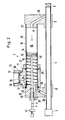
- FIG. 2 shows a longitudinal section through the metering device 3 with feed line 4.
- a piston 14 with a piston rod 15 is arranged in the filling cylinder 10.
- the piston rod 15 runs in the holder 8 and is guided in a bush 25.
- the piston rod 15 protrudes outward from the interior of the filling cylinder 10. It serves the manual return of the piston 14 from an end position to a starting position. Markings x, y are plotted on the piston rod 15, which correspond to a specific metering volume of detergent additive.
- the piston 14 is sealed against the inner wall 38 of the filling cylinder 10 with the aid of an O-ring 16.
- the filling device 11 has a bushing 17, which is rotatably mounted about the axis of the filling cylinder 10. 2, the filling device 11 assumes the "filling" position. After filling, it is pivoted into a position perpendicular to the plane of the drawing or until the storage container touches the feed line.
- the socket 17 has in its interior a filling channel 18 for the detergent additive. This corresponds to an opening 21 in the peripheral wall 22 of the filling cylinder 10.
- a storage container (not shown in FIG. 2) is connected to the connection 12 via a thread 19. Sealing rings 20, 24 ensure the necessary tightness.
- a locking ring 23 prevents the filling device 11 from slipping axially.
- the filling device 11 in turn has two O-rings 25 for sealing the filling cylinder 10.
- An actuating channel 26 runs in the interior of the holder 9. To avoid pressure losses, it is angled at an obtuse angle ⁇ . Its opening on an end face 27 of the filling cylinder 10 is arranged in the center, so that the partial flow of a cleaning liquid flowing in the actuating channel 26 strikes the piston 14 centrally.
- a metering channel 28 is arranged in the holder 8. It is also angled, including an obtuse angle ⁇ .
- the detergent additive located in the filling cylinder 10 flows through it into the feed line 4. There, the detergent additive mixes with the cleaning liquid.
- a throttle element 29 in the form of a throttle screw protrudes into the metering channel 28, with the aid of which the volume flow of the detergent additive can be adjusted.
- the partial flow of the cleaning liquid flowing through the actuating channel 26 presses the cleaning agent additive located beyond the piston 14 in the filling cylinder 10 via the metering channel 28 into the feed line 4.
- the volume flow of the cleaning agent additive is of that Pressure of the partial flow and the setting of the throttle screw 29 dependent. If the filling cylinder 10 is emptied, the piston 14 remains in the end position reached. Later, it can be manually returned to its starting position shown in FIG. 2 with the aid of its piston rod 16, the filling device 11 being pivoted into the filling position shown in FIG. 2. In this way, detergent additive is filled into the filling cylinder 10. Once the desired dosing volume has been reached, the filling device 11 is pivoted into a position perpendicular to the plane of the drawing or even further. Now the dosing process described above can be repeated.
- FIG. 3 shows a side view of the bushing 17 of the filling device 11, which has a socket 30 with an external groove 31 perpendicular to the longitudinal axis.
- the connection 12 is connected to the socket 17 by means of a spring ring inserted into the external groove.
- connection 12 has a flange 32.
- the mouth 33 of a storage container 13 sits on the flange 32.
- the storage container 13 has a thread 35 on its neck 34.
- the container 13 is fastened to the connection 12 with a securing element 36 in the form of a union nut .
- the arrangement is such that the feed line 10 is not arranged below but next to the filling cylinder 10, the bore 21 remaining at the top. Then you can swivel the filling device 11 from a position in which the storage container 13 hangs down by 180 ° into the filling position in which the storage container 13 empties into the filling cylinder (cf. FIG. 4).
- FIG. 5 shows a section of a piston 14, which in this embodiment is sealed against the inner wall 38 of the filling cylinder 10 with the aid of a lip seal 37.
- the piston 14 can be loaded by a return spring.
- a stop 41 can be screwed onto the piston rod 15, which determines the maximum piston stroke and thus the metering volume.
- FIG. 6 shows an alternative embodiment of the metering device according to the invention.
- a feed connection 43 with a tap 6 ' is arranged on the outside 42 of the holder 9.
- This feed connection 43 is connected on the one hand via an actuating channel 45 parallel to the filling cylinder axis to the interior 46 of the filling cylinder 10, and on the other hand via an inclined connecting channel 44 to the feed line 4.
- the actuation channel 45 ends in the middle in the end face 27 of the filling cylinder 10. Due to the straight course of the actuation channel 45 and its direct connection with the tap 6 ', the partial flow flowing through the actuating channel strikes the piston 14 at a higher pressure.
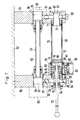
- two identical brackets 50 and 51 are provided, which are fastened to a wall 52.
- the holder 50 has two threaded bores 53 and 54 which are connected to one another via a transverse bore 55 which is closed on the outside by a screw 55 '.
- the holder 51 has two threaded bores 56 and 57, which are connected to one another via a transverse bore 59 closed on the outside by a screw 58. Both cross bores have a throttle element 60 or 61 in the form of an adjustable and lockable valve tap.
- the threaded bores 53 and 56 are connected to one another via a tube 62, which forms part of the feed line 63.
- the threaded bore 53 serves as a connection 64 for a line system.
- this connection can be provided with a plug-in coupling 65 shown in dashed lines, which receives the supply connection of a four-way valve of a cleaning device.
- the threaded bores 56 and 57 form connections 66 and 67 for the supply of a working fluid and / or an actuating pressure medium, as will be described in more detail in connection with FIGS. 8 and 9.
- a connection that is not required can be blocked off by a screw plug 68 shown in broken lines.
- a filling cylinder 69 made of acrylic glass is held by connecting pieces 70 and 71 of the holders 50 and 51, respectively.
- the associated piston 72 is provided on one side with a piston rod 73 which is led out to the outside via seals 74 and 75.
- the piston divides the filling cylinder into an actuating space 76, which is connected to the connection 67 via an actuating channel 77, and a filling space 78, which is accessible from the outside via an opening 79 in the filling cylinder 69.
- a filling device 80 also serves here a bushing 81 which can be rotated around the filling cylinder 69 and which has a connection 82 for a storage container.
- the bushing 81 is provided with an axial groove 83, via which the first opening 79 is connected to a second opening 84 in the filling cylinder 69 and further to channels 85 in an insert 86.
- the opening 84, the channel 85, the threaded bore 54 and the transverse bore 55 accordingly form a metering channel 87, via which the filling space 78 can be emptied.
- openings 79 and 84 are shown offset by 90 °, in reality they point upwards and therefore the storage container hangs down during this metering process.
- the axial groove 83 is opposite the mouth of a filling channel 88, which is provided with a check valve 89 which closes towards the reservoir. Therefore, if one swings the filling device 80 with the storage container upward by 180 °, the filling channel 88 comes into agreement with the first opening 79, so that when the piston 72 is moved with the aid of the piston rod 73 dosing agent reaches the dosing space 78 to the right.
- the filling device 80 also has a ventilation channel 90 which interacts with a stationary channel 91 when the storage container is in the lower position. This means that the fixed channel 91 has also been drawn offset by 90 °.
- the dosing device of FIG. 7 is illustrated schematically, but with the storage container 92 attached in the starting position before the dosing agent is dispensed.
- Working fluid for example water
- the main part of this working liquid reaches the connection 64 via the throttle element 61 and the feed line 63.
- a small part of the working liquid passes through the actuating channel 77 into the actuating space 76 of the filling cylinder 69 and presses the piston 72 to the left.
- the dosing agent also reaches the port 64 via the dosing channel 87 and the throttle element 40, where it mixes with the working fluid.
- the piston 72 moves to the left because the effective piston area on the left because of the piston rod 73 is smaller than the effective piston area on the right side. If the force thus applied is not sufficient, the throttle element 61 can be brought into a throttle position. The resulting drop in pressure leads to larger forces acting on the piston 72. If, on the other hand, the piston speed is too high, throttling with the aid of the throttle element 60 can reduce the delivery speed.
- the piston is not actuated by the working fluid, but rather by a pressure medium, for example a compressed gas such as CO2, which is supplied separately via the connection 67.
- a pressure medium for example a compressed gas such as CO2
- the working fluid is then fed to port 66.
- the throttle element 61 is used to shut off the transverse bore 59.
- the metering volume can be adjusted using the throttle element 60.
- FIGS. 10 to 13 reference numerals increased by 100 compared to FIG. 7 are used for corresponding parts.
- Fig. 10 the parts 97, 99, 100, 101, 103 and 182 of the cylinder 169 and the sleeve 181 are drawn rotated into the plane of the drawing for better understanding; the correct position is shown in FIGS. 11 and 12.
- the transparent filling cylinder 169 has a scale 93 which, with the piston 172 as a pointer, indicates the filling level in the filling chamber 178.
- the bushing 181 of the filling device 180 can be rotated by approximately 180 ° into the first rotational position from the second rotational position illustrated in FIG. 12, in which the connection 182 for the storage container lies at the bottom.
- the end positions are determined by a stop 94 on the bushing 181, which can come into contact with counter-stops 95 and 96 on the holder 150.
- a first control opening 97 in the wall of the filling cylinder 169 interacts with a second control opening 98 in the bushing 181, which is connected to the filling channel 99.
- the first control opening 97 interacts with a third control opening 100 arranged in the bushing 181, which are connected to a first section 101 of the metering channel 187 formed by an axially parallel bore.
- This bore opens into the end face 102 of the bushing 181 and forms a fourth control opening 103 there.
- this cooperates with a fifth control opening 104 in the end face 105 of the holder 150, which is connected to a second section 106 of the metering channel 187.
- the fourth control opening 103 is covered by the end face 105.
- a further axially parallel bore 107 extends from the filling channel 99.
- a sixth control opening 108 which, in a rotational position located between the first and second rotational positions, interacts with a seventh control opening 109 which is connected to a channel 110 going to the atmosphere and the effective range of which is extended by a groove 111. If necessary, one of the cooperating control openings can be surrounded by a seal, as illustrated by the corresponding groove 112 in FIG. 11.
- the second section 106 of the metering channel 187 opens into a transverse bore 113, into which a rotary slide valve 114 is inserted, which can be rotated by means of a handle part 115.
- the rotary slide valve In the area of the mouth of section 106, the rotary slide valve has a groove 116 which can be brought into more or less large engagement with the mouth mentioned. This results in a throttle element 160.
- the groove 116 is connected via a transverse bore 117 and longitudinal bore 118 to a check valve 189, the ball of which is held in the correct position by a screw insert 119.
- this check valve 189 opens and connects the second section 106 of the metering channel 187 via the transverse bore 155 to the threaded bore 153.
- a spring ring 120 presses the bushing 181 against the holder 150, so that there is sufficient sealing of the flow paths in the region of the end face 102 and the end face 105 by means of the illustrated sealing rings.
- the illustrated metering device can be used not only in connection with a device for cleaning pipelines, but also for other purposes, for example the metered supply of detergent or softener in a washing machine, the supply of soap suds in a washroom or the supply of chemicals in one Laboratory.
Landscapes
- Mechanical Engineering (AREA)
- Engineering & Computer Science (AREA)
- Filling Of Jars Or Cans And Processes For Cleaning And Sealing Jars (AREA)
- Cleaning In General (AREA)
- Electrical Discharge Machining, Electrochemical Machining, And Combined Machining (AREA)
- Paper (AREA)
- Feeding, Discharge, Calcimining, Fusing, And Gas-Generation Devices (AREA)
- Devices For Dispensing Beverages (AREA)
- Pharmaceuticals Containing Other Organic And Inorganic Compounds (AREA)
- Basic Packing Technique (AREA)
- Domestic Plumbing Installations (AREA)
- Soy Sauces And Products Related Thereto (AREA)
- External Artificial Organs (AREA)
- Cleaning By Liquid Or Steam (AREA)
Applications Claiming Priority (4)
| Application Number | Priority Date | Filing Date | Title |
|---|---|---|---|
| DE4010962 | 1990-04-05 | ||
| DE4010962 | 1990-04-05 | ||
| DE4036083A DE4036083C2 (de) | 1990-04-05 | 1990-11-13 | Dosiereinrichtung |
| DE4036083 | 1990-11-13 |
Publications (3)
| Publication Number | Publication Date |
|---|---|
| EP0450477A2 true EP0450477A2 (fr) | 1991-10-09 |
| EP0450477A3 EP0450477A3 (en) | 1992-12-02 |
| EP0450477B1 EP0450477B1 (fr) | 1994-09-21 |
Family
ID=25891897
Family Applications (1)
| Application Number | Title | Priority Date | Filing Date |
|---|---|---|---|
| EP91104841A Expired - Lifetime EP0450477B1 (fr) | 1990-04-05 | 1991-03-27 | Doseur |
Country Status (11)
| Country | Link |
|---|---|
| US (1) | US5088517A (fr) |
| EP (1) | EP0450477B1 (fr) |
| JP (1) | JPH0686963A (fr) |
| AT (1) | ATE111784T1 (fr) |
| BR (1) | BR9101370A (fr) |
| CS (1) | CS91491A2 (fr) |
| DE (2) | DE4036083C2 (fr) |
| HR (1) | HRP920984A2 (fr) |
| HU (1) | HUH3674A (fr) |
| IE (1) | IE910885A1 (fr) |
| RU (1) | RU2037783C1 (fr) |
Cited By (2)
| Publication number | Priority date | Publication date | Assignee | Title |
|---|---|---|---|---|
| DE19953720A1 (de) * | 1999-11-09 | 2001-05-23 | Beviclean Gmbh | Verfahren, Vorrichtung und Reinigungsmittelzusatz zur chemischen Reinigung von Rohrleitungen |
| WO2016184936A1 (fr) * | 2015-05-19 | 2016-11-24 | Exel Industries | Système de mélange d'un produit chimique avec de l'eau |
Families Citing this family (21)
| Publication number | Priority date | Publication date | Assignee | Title |
|---|---|---|---|---|
| US5246168A (en) * | 1991-12-05 | 1993-09-21 | Richard Williams | Liquid additives dispenser for sprinkler systems |
| US5366159A (en) * | 1992-09-14 | 1994-11-22 | Childers Lance L | Automatic lawn and garden feeding apparatus |
| DE19624791A1 (de) * | 1996-06-21 | 1998-01-02 | Heinz Stricker | Vorrichtung zum Reinigen von getränkeführenden Zapfleitungen |
| FR2843798B1 (fr) * | 2002-08-21 | 2005-02-11 | Tremark Technologies Inc | Machine doseuse |
| US6802909B1 (en) | 2003-04-24 | 2004-10-12 | Doyle J. Crenshaw | Method for improving the operation of a pipeline by employing soap pigs |
| GB0522660D0 (en) * | 2005-11-07 | 2005-12-14 | Reckitt Benckiser Nv | Assembly and device |
| WO2007083139A1 (fr) | 2006-01-21 | 2007-07-26 | Reckitt Benckiser N.V. | Article |
| BRPI0707877A2 (pt) * | 2006-01-21 | 2011-05-10 | Reckitt Benckiser Nv | elemento de dosagem e cÂmara |
| NL1032098C2 (nl) * | 2006-06-30 | 2008-01-02 | Heineken Supply Chain Bv | Tapinrichting, drankcontainer, koppelingsinrichting en werkwijze met reinigingselement. |
| WO2008053179A1 (fr) * | 2006-10-30 | 2008-05-08 | Reckitt Benckiser Production (Poland) Sp.Zo.O. | Composition de détergent comprimée |
| GB0621576D0 (en) * | 2006-10-30 | 2006-12-06 | Reckitt Benckiser Nv | Device status indicator |
| GB0621569D0 (en) * | 2006-10-30 | 2006-12-06 | Reckitt Benckiser Nv | Mounting device |
| GB0621572D0 (en) * | 2006-10-30 | 2006-12-06 | Reckitt Benckiser Nv | Multi-dosing detergent delivery device |
| GB0621570D0 (en) * | 2006-10-30 | 2006-12-06 | Reckitt Benckiser Nv | Multi-dosing detergent delivery device |
| GB0710229D0 (en) * | 2007-05-30 | 2007-07-11 | Reckitt Benckiser Nv | Detergent dosing device |
| US20140251390A1 (en) * | 2013-03-05 | 2014-09-11 | Generac Power Systems, Inc. | Pressure Washer With Parallel Flow Soap Dispensing |
| JP6972608B2 (ja) * | 2017-03-27 | 2021-11-24 | 日本電産トーソク株式会社 | スプールバルブ |
| US11964070B2 (en) * | 2020-06-09 | 2024-04-23 | Quin Global US, Inc. | Disinfectant and sanitizer canister system and metering device for system |
| WO2022261724A1 (fr) * | 2021-06-17 | 2022-12-22 | Zip Heaters (Aust) Pty Ltd | Système de désinfection pour systèmes d'eau potable |
| RU2770823C1 (ru) * | 2021-10-04 | 2022-04-22 | Федеральное государственное бюджетное образовательное учреждение высшего образования Костромская государственная сельскохозяйственная академия | Устройство для получения рабочего раствора в напорном трубопроводе |
| CN115183003B (zh) * | 2022-08-04 | 2025-05-30 | 铜陵兴荣阀门管件有限公司 | 一种组合式蝶阀 |
Family Cites Families (19)
| Publication number | Priority date | Publication date | Assignee | Title |
|---|---|---|---|---|
| GB395547A (en) * | 1932-06-17 | 1933-07-20 | Louis Stevens | Apparatus for returning beverage from the delivery pipe of a cask or the like into the cask and simultaneously cleansing said delivery pipe |
| US2217750A (en) * | 1938-03-28 | 1940-10-15 | Hockenstrom Albert | Fluid fuel burning stove |
| US2618510A (en) * | 1946-05-25 | 1952-11-18 | Lindley E Mills | Fluid proportioning apparatus |
| FR1027597A (fr) * | 1950-11-13 | 1953-05-13 | Appareil destiné à injecter une masse fluide dans un courant de liquide | |
| US3200840A (en) * | 1962-07-25 | 1965-08-17 | Watts John Henry | Pressure operated chemical injector |
| DE2611493A1 (de) * | 1976-03-18 | 1977-09-22 | Provera Gmbh | Dosiergeraet fuer fluessigkeiten mit einstellbarer dosiermenge insbesonder fuer hausgeraete |
| DE2622125C2 (de) * | 1976-05-18 | 1981-12-03 | Bosch-Siemens Hausgeräte GmbH, 7000 Stuttgart | Nachfüllbehälter für pumpbare Waschmittel-Wirkstoffe |
| US4358056A (en) * | 1979-12-28 | 1982-11-09 | Emmett Laboratories, Inc. | Shower dispenser |
| US4399932A (en) * | 1981-06-02 | 1983-08-23 | Guenter Zimmermann | Volumetric metering valve |
| DE3130003A1 (de) * | 1981-07-30 | 1983-03-17 | Walter 6650 Homburg Imbsweiler | "reinigungsgeraet fuer getraenkeleitungen in schankanlagen" |
| DE3320293C2 (de) * | 1983-06-04 | 1985-05-30 | Friedrich 5401 Halsenbach Bersch | Vorrichtung zum Reinigen von Rohrleitungen, insbesondere Bierleitungen |
| DE3347004C1 (de) * | 1983-12-24 | 1985-06-05 | Friedrich 5401 Halsenbach Bersch | Vorrichtung zur Reinigung von Rohrleitungen,insbesondere Schankleitungen |
| DE3347003C2 (de) * | 1983-12-24 | 1986-12-18 | Friedrich 5401 Halsenbach Bersch | Verfahren und Vorrichtung zum Reinigen von Rohrleitungen, insbesondere Schankleitungen |
| US4691721A (en) * | 1984-12-07 | 1987-09-08 | Ecolab Inc. | Volumetric gravity feed liquid dispenser |
| FR2602967B1 (fr) * | 1986-08-20 | 1990-06-08 | Colgate Palmolive Co | Dispositif doseur de produits lessiviels pour machine a laver la vaisselle |
| US4832072A (en) * | 1987-09-15 | 1989-05-23 | Valentine Hechler | Fluid proportioning and mixing system |
| DE3824860A1 (de) * | 1988-07-21 | 1990-01-25 | Friedrich Bersch | Vorrichtung zur reinigung von rohrleitungen, insbesondere schankleitungen |
| EP0351664B1 (fr) * | 1988-07-21 | 1994-02-23 | Friedrich Bersch | Dispositif de nettoyage de tuyauteries, en particulier de canalisations de bière |
| US4971105A (en) * | 1990-01-16 | 1990-11-20 | Mcguire George E | Hydraulic fluid injection apparatus |
-
1990
- 1990-11-13 DE DE4036083A patent/DE4036083C2/de not_active Expired - Fee Related
-
1991
- 1991-03-15 IE IE088591A patent/IE910885A1/en unknown
- 1991-03-27 DE DE59102987T patent/DE59102987D1/de not_active Expired - Fee Related
- 1991-03-27 HU HU100391A patent/HUH3674A/hu unknown
- 1991-03-27 AT AT91104841T patent/ATE111784T1/de not_active IP Right Cessation
- 1991-03-27 EP EP91104841A patent/EP0450477B1/fr not_active Expired - Lifetime
- 1991-04-02 RU SU4894864 patent/RU2037783C1/ru active
- 1991-04-03 JP JP9962191A patent/JPH0686963A/ja active Pending
- 1991-04-03 CS CS91914A patent/CS91491A2/cs unknown
- 1991-04-03 US US07/679,750 patent/US5088517A/en not_active Expired - Fee Related
- 1991-04-04 BR BR9101370A patent/BR9101370A/pt unknown
-
1992
- 1992-10-02 HR HRP920984AA patent/HRP920984A2/hr not_active Application Discontinuation
Cited By (6)
| Publication number | Priority date | Publication date | Assignee | Title |
|---|---|---|---|---|
| DE19953720A1 (de) * | 1999-11-09 | 2001-05-23 | Beviclean Gmbh | Verfahren, Vorrichtung und Reinigungsmittelzusatz zur chemischen Reinigung von Rohrleitungen |
| DE19953720C2 (de) * | 1999-11-09 | 2001-11-29 | Beviclean Gmbh | Verfahren, Vorrichtung und Reinigungsmittelzusatz zur chemischen Reinigung von Rohrleitungen |
| EP1099487A3 (fr) * | 1999-11-09 | 2003-04-02 | BeviClean GmbH | Procédé, dispositif et additif détergent pour le nettoyage chimique de conduites |
| WO2016184936A1 (fr) * | 2015-05-19 | 2016-11-24 | Exel Industries | Système de mélange d'un produit chimique avec de l'eau |
| FR3036296A1 (fr) * | 2015-05-19 | 2016-11-25 | Exel Ind | Systeme de melange d'un produit chimique avec de l'eau |
| US10391463B2 (en) | 2015-05-19 | 2019-08-27 | Exel Industries | System for mixing a chemical product with water |
Also Published As
| Publication number | Publication date |
|---|---|
| DE4036083C2 (de) | 1994-06-16 |
| CS91491A2 (en) | 1991-10-15 |
| EP0450477B1 (fr) | 1994-09-21 |
| US5088517A (en) | 1992-02-18 |
| EP0450477A3 (en) | 1992-12-02 |
| HUH3674A (en) | 1993-07-28 |
| HU911003D0 (en) | 1991-10-28 |
| JPH0686963A (ja) | 1994-03-29 |
| IE910885A1 (en) | 1991-10-09 |
| BR9101370A (pt) | 1991-11-26 |
| DE59102987D1 (de) | 1994-10-27 |
| ATE111784T1 (de) | 1994-10-15 |
| RU2037783C1 (ru) | 1995-06-19 |
| DE4036083A1 (de) | 1991-10-10 |
| HRP920984A2 (hr) | 1994-04-30 |
Similar Documents
| Publication | Publication Date | Title |
|---|---|---|
| EP0450477B1 (fr) | Doseur | |
| DE4236381C2 (de) | Reinigungsvorrichtung für Getränkezapfanlagen | |
| DE3916952C1 (fr) | ||
| DE1598222A1 (de) | Verfahren und Einrichtung zum selbstaendigen Eintragen von Proben in chromatographische Kolonnen | |
| EP0096377B1 (fr) | Dispositif pour la mise en disponibilité d'eau de haute pureté et stérile | |
| DE2730375A1 (de) | Anlage zum mischen und ausgeben mindestens zweier fluider medien | |
| DE7812351U1 (de) | Regulierbare pipette zum abgeben fluessiger proben | |
| DE3704901A1 (de) | Fuellventil | |
| EP0011155A1 (fr) | Adaptateur de remplissage | |
| EP0043493B1 (fr) | Dispositif pour le développement de matériel photographique | |
| DE69005846T2 (de) | Reinigungsgerät für Behälter. | |
| DE4223006C2 (de) | Vorrichtung zum Behandeln von Werkstücken mit einem Druckfluid | |
| DE3221589C2 (de) | Vorrichtung zur selbsttätigen Herstellung von Wischwasser | |
| EP0363848B1 (fr) | Pistolet de distribution | |
| DE2744776C3 (de) | Vorrichtung zum Wechseln von Schmieröl in Maschinen | |
| EP4467481B1 (fr) | Couvercle pour fermer un récipient de liquide, récipient, système et procédé pour injecter un gaz dans le récipient | |
| DE3124125A1 (de) | Hochdruck-spruehpistole | |
| DE3100708A1 (de) | Dosiervorrichtung | |
| CH679377A5 (fr) | ||
| EP0899027A2 (fr) | Procédé de fonctionnement d'un dispositif à haute pression, en particulier un nettoyeur à haute pression, et dispositif à haute pression | |
| DE3320293C2 (de) | Vorrichtung zum Reinigen von Rohrleitungen, insbesondere Bierleitungen | |
| DE8713372U1 (de) | Zapfhahn zum Ausschenken von schäumenden Getränken | |
| DE68923620T2 (de) | Anordnung zum selektiven spenden und mischen von mehreren getränken. | |
| DE7833183U1 (de) | Fülladapter | |
| DE3509294A1 (de) | Vorrichtung zum dosieren von hochviskosen fluessigkeiten und/oder massen |
Legal Events
| Date | Code | Title | Description |
|---|---|---|---|
| PUAI | Public reference made under article 153(3) epc to a published international application that has entered the european phase |
Free format text: ORIGINAL CODE: 0009012 |
|
| AK | Designated contracting states |
Kind code of ref document: A2 Designated state(s): AT BE CH DE DK ES FR GB GR IT LI LU NL SE |
|
| PUAL | Search report despatched |
Free format text: ORIGINAL CODE: 0009013 |
|
| AK | Designated contracting states |
Kind code of ref document: A3 Designated state(s): AT BE CH DE DK ES FR GB GR IT LI LU NL SE |
|
| 17P | Request for examination filed |
Effective date: 19921106 |
|
| 17Q | First examination report despatched |
Effective date: 19940222 |
|
| GRAA | (expected) grant |
Free format text: ORIGINAL CODE: 0009210 |
|
| AK | Designated contracting states |
Kind code of ref document: B1 Designated state(s): AT BE CH DE DK ES FR GB GR IT LI LU NL SE |
|
| PG25 | Lapsed in a contracting state [announced via postgrant information from national office to epo] |
Ref country code: IT Free format text: LAPSE BECAUSE OF FAILURE TO SUBMIT A TRANSLATION OF THE DESCRIPTION OR TO PAY THE FEE WITHIN THE PRE;WARNING: LAPSES OF ITALIAN PATENTS WITH EFFECTIVE DATE BEFORE 2007 MAY HAVE OCCURRED AT ANY TIME BEFORE 2007. THE CORRECT EFFECTIVE DATE MAY BE DIFFERENT FROM THE ONE RECORDED.SCRIBED TIME-LIMIT Effective date: 19940921 Ref country code: GB Effective date: 19940921 Ref country code: ES Free format text: THE PATENT HAS BEEN ANNULLED BY A DECISION OF A NATIONAL AUTHORITY Effective date: 19940921 Ref country code: FR Effective date: 19940921 Ref country code: NL Effective date: 19940921 Ref country code: BE Effective date: 19940921 Ref country code: DK Effective date: 19940921 Ref country code: GR Free format text: LAPSE BECAUSE OF FAILURE TO SUBMIT A TRANSLATION OF THE DESCRIPTION OR TO PAY THE FEE WITHIN THE PRESCRIBED TIME-LIMIT Effective date: 19940921 |
|
| REF | Corresponds to: |
Ref document number: 111784 Country of ref document: AT Date of ref document: 19941015 Kind code of ref document: T |
|
| REF | Corresponds to: |
Ref document number: 59102987 Country of ref document: DE Date of ref document: 19941027 |
|
| PG25 | Lapsed in a contracting state [announced via postgrant information from national office to epo] |
Ref country code: SE Effective date: 19941221 |
|
| EN | Fr: translation not filed | ||
| NLV1 | Nl: lapsed or annulled due to failure to fulfill the requirements of art. 29p and 29m of the patents act | ||
| PG25 | Lapsed in a contracting state [announced via postgrant information from national office to epo] |
Ref country code: AT Effective date: 19950327 |
|
| GBV | Gb: ep patent (uk) treated as always having been void in accordance with gb section 77(7)/1977 [no translation filed] |
Effective date: 19940921 |
|
| PG25 | Lapsed in a contracting state [announced via postgrant information from national office to epo] |
Ref country code: CH Effective date: 19950331 Ref country code: LI Effective date: 19950331 Ref country code: LU Free format text: LAPSE BECAUSE OF NON-PAYMENT OF DUE FEES Effective date: 19950331 |
|
| PLBE | No opposition filed within time limit |
Free format text: ORIGINAL CODE: 0009261 |
|
| STAA | Information on the status of an ep patent application or granted ep patent |
Free format text: STATUS: NO OPPOSITION FILED WITHIN TIME LIMIT |
|
| 26N | No opposition filed | ||
| REG | Reference to a national code |
Ref country code: CH Ref legal event code: PL |
|
| PGFP | Annual fee paid to national office [announced via postgrant information from national office to epo] |
Ref country code: DE Payment date: 19960318 Year of fee payment: 6 |
|
| PG25 | Lapsed in a contracting state [announced via postgrant information from national office to epo] |
Ref country code: DE Effective date: 19971202 |