EP0450528A2 - Lecteur de disques - Google Patents
Lecteur de disques Download PDFInfo
- Publication number
- EP0450528A2 EP0450528A2 EP91105055A EP91105055A EP0450528A2 EP 0450528 A2 EP0450528 A2 EP 0450528A2 EP 91105055 A EP91105055 A EP 91105055A EP 91105055 A EP91105055 A EP 91105055A EP 0450528 A2 EP0450528 A2 EP 0450528A2
- Authority
- EP
- European Patent Office
- Prior art keywords
- disc
- pickup
- tray
- drive
- cam
- Prior art date
- Legal status (The legal status is an assumption and is not a legal conclusion. Google has not performed a legal analysis and makes no representation as to the accuracy of the status listed.)
- Granted
Links
Images


Classifications
-
- G—PHYSICS
- G11—INFORMATION STORAGE
- G11B—INFORMATION STORAGE BASED ON RELATIVE MOVEMENT BETWEEN RECORD CARRIER AND TRANSDUCER
- G11B17/00—Guiding record carriers not specifically of filamentary or web form, or of supports therefor
- G11B17/02—Details
- G11B17/04—Feeding or guiding single record carrier to or from transducer unit
- G11B17/05—Feeding or guiding single record carrier to or from transducer unit specially adapted for discs not contained within cartridges
- G11B17/053—Indirect insertion, i.e. with external loading means
- G11B17/056—Indirect insertion, i.e. with external loading means with sliding loading means
- G11B17/0565—Indirect insertion, i.e. with external loading means with sliding loading means adapted for discs of different sizes
-
- G—PHYSICS
- G11—INFORMATION STORAGE
- G11B—INFORMATION STORAGE BASED ON RELATIVE MOVEMENT BETWEEN RECORD CARRIER AND TRANSDUCER
- G11B17/00—Guiding record carriers not specifically of filamentary or web form, or of supports therefor
- G11B17/02—Details
- G11B17/022—Positioning or locking of single discs
- G11B17/028—Positioning or locking of single discs of discs rotating during transducing operation
- G11B17/0288—Positioning or locking of single discs of discs rotating during transducing operation by means for moving the turntable or the clamper towards the disk
Definitions
- the present invention relates a disc player adapted to record signals on or reproduce signals from disclike recording media such as compact discs or laser discs.
- Disc players are already known in which a disc on a tray is transported horizontally to a position above a turntable, which is then raised to lift the disc off the tray and eventually press the disc against a clamp positioned above the turntable (Unexamined Japanese Patent Publication SHO 61-145758).
- the disc player described comprises a main chassis fixedly provided inside a cabint, and a subchassis supported on the main chassis upwardly and downwardly movably and having mounted thereon a turntable assembly, pickup assembly, etc.
- the turntable rises therewith to lift the disc off the tray.
- the subchassis carries thereon not only the turntable assembly but also the pickup assembly including a feed motor specific thereto, etc., so that the liftable arrangement including the subchassis is large-sized and heavy. Consequently, the upward and downward movement of the subchassis requires a motor specific thereto and having a great capacity and a large mechanism, and further necessitates a large space since the subchassis is large. This entails the problem of increasing the weight and size of the entire player.
- the pickup assembly is mounted on the fixed chassis.
- the pickup must be disposed at a level a small distance from the disc on the turntable as raised to its upper limit position, so that if the distance, which is determined by the optical system, is small, the pickup must inevitably be positioned at a higher level than the path of horizontal travel of the tray. The tray or the disc thereon will then collide with the pickup.
- the conventional disc player described requires, in addition to a spindle motor for driving the turntable, at least a number of motors, i.e., a motor mounted on the main chassis for driving the subchassis upward and downward, and a pickup transport motor and tray drive motor which are mounted on the subchassis.
- the many motors required entail the problem of not only making the disc player larger and heavier but also necessitating circuits for driving the respective motors to render the electric circuit of the player complex in construction.
- An object of the present invention is to provide a disc player wherein the turntable and the spindle motor only are adapted to be driven upward and downward to render the liftable arrangement small-sized and lightweight and thereby reduce the size and weight of the entire player.
- Another object of the invention is to provide a disc player wherein except for the spindle motor for driving the turntable, a single motor is adapted to reciprocatingly drive the tray, to drive the spindle motor upward and downward and to transport the pickup to thereby render the player compacted and lightweight and simplify the circuit construction thereof.
- Another object of the invention is to provide a pickup assembly for use in disc players wherein the pickup can be retracted to a position free of interference with the tray during tray loading.
- the disc player of the present invention comprises a tray drive mechanism, a disc clamp mechanism and a pickup assembly which are mounted on a fixed chassis, and a spindle motor which is coupled to a motor lift mechanism and drivable upward and downward relative to the chassis.
- a turntable attached to the output shaft of the spindle motor is upwardly movable from a standby position below a tray in a loading completed position through a central opening of the tray to a disc clamping completed position where the disc can be pressed into contact with a clamp of the disc clamp mechanism.
- a drive gear mechanism drivable by a loading motor is provided on the fixed chassis.
- the drive gear mechanism has a plurality of output portions coupled to the tray drive mechanism, the motor lift mechanism and the pickup assembly, respectively, and a power transmission change-over mechanism for transmitting the power of the loading motor selectively to one of these mechanisms and assembly.
- a disc is placed on the tray in a disc discharge position, and the tray is thereafter transported to the loading completed position by the tray drive mechanism.
- the turntable and the spindle motor are in the standby position lower than the level of the tray.
- the motor lift mechanism starts to operate, raising the turntable from the standby position along with the spindle motor. In this process, the turntable moves through the central opening of the tray while lifting the disc off the tray and presses the disc against the clamp of the disck clamp mechanism by a further upward movement.
- the spindle motor is initiated into operation to drivingly rotate the disc, and the pickup assembly operates to record or reproduce signals.
- the gear mechanism drives the tray drive mechanism, the motor lift mechanism and the pickup assembly
- the gear mechanism is coupled first to the tray drive mechanism to drive the tray.
- the drive gear mechanism is coupled to the motor lift mechanism to drive the spindle motor and the turntable upward.
- the gear mechanism is thereafter coupled to the pickup assembly to transport the pickup.
- the liftable arrangement which does not include the pickup assembly, is smaller in size and weight than in the prior art and movable upward and downward by a simplified mechanism in a smaller space. This serves to render the entire player small-sized and lightweight.
- the tray drive mechanism, the motor lift mechanism and the pickup assembly are mounted in common on the chassis, so that the drive gear mechanism for selectively driving them commonly by the loading motor can be realized by a simple construction. This makes the player further smaller and more lightweight and nevertheless renders the circuit construction simpler than conventionally.
- the pickup of the pickup assembly included in the disc player of the invention is mounted on a slide base upwardly and downwardly movably.
- the slide base is disposed on the chassis and reciprocatingly movable along a radial line of the turntable.
- the slide base is reciprocatingly driven between a first position opposed to the innermost peripheral portion of the disc on the turntable and a second position opposed to or further outward of the outermost peripheral portion of the disc.
- the pickup is supported on the slide base upwardly and downwardly movably.
- the pickup is driven upward and downward between a retracted position below the path of reciprocating movement of the tray and a raised position close to the tray for recording or reproducing signals.
- the pickup With the pickup assembly of the disc player, the pickup is set in the retracted position while the tray is being driven from the disc discharge position to the loading completed position. This eliminates the likelihood that the tray or the disc on the tray will collide with the pickup.
- the pickup With the tray completely loaded in position, the pickup is driven upward from the retracted position to the raised position for recording or reproducing signals, permitting the pickup to be focused on the signal recording surface of the disc.
- the slide base is thereafter reciprocatingly driven between the first position and the second position, causing the pickup to record signals on or reproduce signals from the disc on the turntable.
- the pickup With the pickup assembly of the disc player embodying the invention, the pickup can be held in the retracted position free of interference with the tray during tray loading. Accordingly, even if the focusing range of the pickup is small, collision of the tray or disc with the pickup is avoidable.
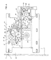
- a tray 44 is retractably disposed at a front panel opening 11 of a cabinet 1.
- the tray 44 is reciprocatingly movable by being guided by a plurality of guide support members 16 on a chassis 13 fixedly provided inside the cabinet 1.
- a tray drive mechanism 4 for reciprocatingly driving the tray 44
- a motor lift mechanism 5 for upwardly and downwardly driving a spindle motor 51 along with a turntable 50
- a pickup assembly 9 having an optical pickup 90 and a tilting mechanism 100
- a drive gear mechanism 2 for driving these mechanisms and assembly
- a disc clamp mechanism 7 having a clamp 70, etc.
- the turntable 50 is liftably mounted on the chassis 13 as will be described later and is positioned as projected upward through a central aperture 17 formed in the chassis 13.
- the drive gear mechanism 2 is provided with a loading motor 21 as its power source, transmits power to the tray drive mechanism 4 via a belt transmission mechanism 22, first gear 23, second gear 24, intermediate third gear 3, fourth gear 27 and fifth gear 41, provides output means for the pickup assembly 9 by the second gear 24 and a sixth gear 37 in mesh with the third gear 3, and provides output means for upwardly and downwardly driving the turntable 50 by the third gear 3.
- the tray 44 has a portion for supporting different kinds of discs, and this portion is centrally formed with an opening 46 for the turntable 50 to project therethrough.
- FIGS. 10 (a) and (b) are a plan view and a sectional view, respectively, showing the loading motor 21, belt transmission mechanism 22, and first to fifth gears 23, 24, 3, 27 and 41 constituting the drive gear mechanism 2 and arranged in a row along a route of power transmission to the tray drive mechanism 4.
- FIGS. 11 (a) and (b) are a plan view and a sectional view, respectively, showing the loading motor 21, belt transmission mechanism 22, second gear 24, third gear 3 and sixth gear 37 as arranged in a row along a route of power transmission to the pickup assembly 9.
- the second gear 24 has a large gear portion 25 meshing with the first gear 23 at all times, a pinion portion 26 meshable with a rack 98 constituting the pickup assembly 9, and a small gear portion 20.
- the third gear 3 has a primary gear portion 31 formed over the entire circumference thereof and meshing with the small gear portion 20 of the second gear 24, and a secondary gear portion 32 formed with teeth only over a predetermined angular range.
- the primary gear portion 31 has a toothless portion 31a at its upper end approximately over half of its circumference.
- the fourth gear 27 has a small gear portion 28 meshable with the secondary gear portion 32 of the third gear 3, and a large gear portion 29.
- the fifth gear 41 has a gear portion 42 always in mesh with the large gear portion 29 of the fourth gear 27, and a pinion portion 43 always in mesh with a rack 45 constituting the tray drive mechanism 4.
- the sixth gear 37 has a gear portion 38 always in mesh with the primary gear portion 31 of the third gear 3, and a pinion portion 39 always in mesh with the rack 98.
- the third gear 3 is provided above the primary gear portion 31 and the secondary gear portion 32 with first and second projecting faces 34, 35 each in the form of a cylindrical surface and extending over a specified angular range.
- the fourth gear 27 has a recessed face 27a in the form of a cylindrical surface and positioned between the small gear portion 28 and the large gear portion 29.
- the sixth gear 37 has a recessed face 37a in the form of a cylindrical surface and positioned above the pinion portion 39.
- the projecting faces 34, 35 of the third gear 3 are engageable with the recessed face 27a of the fourth gear 27 and the recessed face 37a of the sixth gear 37, respectively.
- the rack 45 is attached to the rear side of the tray 44 and extends in the direction of retraction of the tray.
- the rack 45 is in mesh with the pinion portion 43 of the fifth gear 41.
- the second gear 24 rotates the third gear 3 counterclockwise, bringing the secondary gear portion 32 of the third gear 3 into meshing engagement with the small gear portion 28 of the fourth gear 27, whereby the rotation of the loading motor 21 is further transmitted through the fourth gear 27 to the fifth gear 41, driving the pinion portion 43 of the fifth gear 41 in a direction to load the tray. Consequently, the tray 44 is brought from the disc discharge position shown in FIGS. 1 and 2 into the cabinet as shown in FIG. 3 and is eventually set in the loading completed position shown in FIG. 4. In this state, the front panel opening 11 of the cabinet 1 is closed with the front edge portion of the tray 44.
- the turntable 50 is held in its lower limit position as will be described later, and the pickup 90 is set in a low position free of interference with the tray 44 by the operation of the tilting mechanism 100 (see FIGS. 7 and 8).
- the pinion portion 26 of the second gear 24 is out of meshing engagement with the rack 98 of the pickup assembly 9 (see FIGS. 2 to 4) and is in idle rotation.
- gear portion 38 of the sixth gear 37 shown in FIG. 11 is opposed to the toothless portion 31a of the primary gear portion 31 of the third gear 3, with the recessed face 37a of the sixth rear 37 in engagement with the second projecting face 35 of the third gear 3 as seen in FIGS. 2 to 4, whereby the sixth gear 37 is locked in a halted state. Consequently, there is no likelihood that the rack 98 of the pickup will be driven in this process.
- the secondary gear portion 32 of the third gear 3 is out of mesh with the small gear portion 28 of the fourth gear 27, and the first projecting face 34 of the third gear 3 is in engagement with the recessed face 27a of the fourth gear 27, locking the fourth gear 27 in a halted state. Accordingly, the tray 44 is also locked in the loading completed position in this state.
- the tray 44 is unloaded by the reverse rotation of the loading motor 21 which rotates the fifth gear 41 clockwise.
- two guide shafts 18, 18 extend downward from the rear side of the chassis 13 for guiding the upward and downward movement of a motor base 52.
- the spindle motor 51 is mounted on the motor base 52 and has the turntable 50 fixed to its output shaft.
- a plurality of positioning members 53 are provided on the upper surface of the motor base 52 for determining the upper limit position of the base 52 by contacting with the rear side of the chassis 13.
- the base has three pins 54 projecting from each of its opposite side faces.
- Each of the plates 55 is supported by a plurality of guide members 19 projecting from the rear side of the chassis 13 so as to be reciprocatingly movable in the direction of ejection or retraction of the tray (see FIGS. 7 to 9).
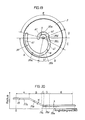
- Each slide drive plate 55 is formed in its inner surface with first to third cam grooves 56, 57 and 58 extending obliquely. As seen in FIG. 13, the first cam groove 56 and the third cam groove 58 are identical in configuration and each have a slanting cam portion 56a or 58a and a horizontal cam portion 56b or 58b.
- the second cam groove 57 has a first slanting cam portion 57a and a second slanting cam portion 57b having a smaller angle of inclination than the first.
- the rear end of the slide drive plate 55 is formed with a slot 55a and an engaging portion 55b.
- An intermediate drive plate 64 and a spring 59 are provided between the slide drive plates 55, 55.
- the intermediate drive plate 64 is provided on its opposite sides with projections 67, 67 loosely fitted in the slots 55a of the respective slide drive plates 55.
- the spring 59 is retained on a support lug 66 extending downward from the front edge of the intermediate drive plate 64 and has opposite ends engaged with the engaging portions 55b of the respective slide drive plates 55, 55.
- the intermediate drive plate 64 has on its upper surface a slotted portion 65 for a pin 62 on a drive lever 6 to engage in.
- the intermediate drive plate 64 when moved rearward by the drive lever 6, causes the spring 59 to pull the two slide drive plates 55, 55 rearward, permitting the cam mechanisms to operate to drive the motor base 52 upward.
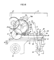
- FIGS. 7 to 9 show how the spindle motor 51 is moved upward. While the tray 44 is being loaded, both the slide drive plates 55 are in their foremost advanced position, with the spindle motor 51 and the turntable 50 in a low standby position free of interference with the tray 44 as shown in FIG. 7.
- the drive lever 6, which is L-shaped, is movably supported by a pivot 60 on the chassis 13.
- the lever 6 is provided at one end thereof with a cam follower 61 engaged in a spiral cam groove 33 formed in the rear surface of the third gear 3.
- the pin 62 on the other lever end is engaged in the slotted portion 65 of the intermediate drive plate 64 as already stated.
- the cam groove 33 of the third gear 3 comprises a first cam portion 33a having a definite radius, second and third cam portions 33b, 33c having a gradually decreasing diameter, a fourth cam portion 33d which is formed by a groove defining outer peripheral wall of increasing radius and which has a groove width increasing from W to X as illustrated, and a fifth cam portion 33e having a definite radius.
- the cam follower 61 of the drive lever 6 engages in the first cam portion 33a while the tray 44 is being driven, in the second and third cam portions 33b, 33c for driving the motor lift mechanism 5, and in the fifth cam portion 33e during the transport of the pickup 90.
- the third gear 3 is driven further counterclockwise, causing the third cam portion 33c of the cam groove 33 to function to bring the intermediate drive plate 64 to the rearward limit position of its movement shown in FIG. 5 and to raise the turntable 50 from the position of FIG. 8 to the position of FIG. 9.
- the disc is therefore held by the clamp 70.
- the disc clamp mechanism 7 gives a clamping force magnetically and is attached to a metal support member 71 secured to the chassis 13 as shown in FIG. 1.
- the support member 71 serves as a yoke in the form of a flat plate.
- the disc clamp mechanism 7 comprises the clamp 70 in the form of a disc, an annular permanent magnet 74, and a holder 75 for holding the magnet 74.
- the magnet 74 fixed to the holder 75 is disposed above the support member 71, and the clamp 70 below the member 71.
- the holder 75 holding the megnet 74, and the clamp 70 are assembled together.
- the clamp 70 has a shank 70a extending loosely through a central opening 72 formed in the support member 71.
- a plurality of seat members 73 for the magnet 74 to rest on are provided on the upper surface of the support member 71.
- the magnet 74 is in intimate contact with the seat members 73 on the support member 71 owing to the magnetic attraction between the magnet 74 and the support member 71 to hold the clamp 70 in a lower limit position away from the support member 71 by the largest distance.
- the clamp 70 is pushed up by the disc 120 on the turntable 50 as shown in FIGS. 8 and 9.
- the magnet 74 is raised off the seat members 73 on the support member 71, forming a specified mgangtic gap G between the magnet 74 and the support member 71 as shown in FIG. 9.
- the size of the magnet 74 can be designed as desired, so that the disc clamp mechanism 7 affords a sufficient clamping force for different kinds of discs.
- the third gear 3 is drivingly rotated clockwise to release the disc from the clamp 70 by lowering the turntable 50.
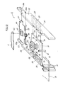
- a guide shaft 92 extending along the direction of ejection or retraction of the tray is supported on the chassis 13 at one side of the turntable 50.
- a slide base 91 having the pickup 90, etc. mounted thereon has one end positioned toward the drive gear mechanism 2 and slidably in engagement with the guide shaft 92, and the other end slidably resting on the chassis 13, whereby the pickup 90 is made reciprocatingly movable accurately along a radial line of the turntable 50.
- the rack 98 is attached to the slide base 91 and extends in the direction of sliding movement thereof.
- the pinion portion 26 of the second gear 24 and the pinion portion 39 of the sixth gear 37 mesh with the rack 98 to reciprocatingly drive the slide base 91.
- a pivotal base 93 having the pickup 90 secured directly thereto is mounted on the slide base 91.
- a pair of pivots 95, 95 projecting outward from opposite sides of the pivotal base 93 is supported on the slide base 91, whereby the pivotal base 93 is supported so as to be movable upward and downward over a predetermined angular range.
- a spring 96 is provided between the pivotal base 93 and the slide base 91 for biasing the base 93 downward.
- the pickup assembly 9 is provided with the tilting mechanism 100 for adjusting the tilt of the optical axis of the pickup 90 for the reproduction of signals.
- the tilting mechanism 100 serves also as a pickup retracting mechanism for pivotally moving the pickup 90 downward along with the pivotal base 93 to avoid the interference of the pickup 90 with the tray 44 while the tray is being loaded as seen in FIG. 8.
- the tilting mechanism 100 comprises, as seen in FIG. 21, a pin 94 projecting rearward from an end portion of the pivotal base 93, a cam member 103 having a helical cam face 104 for the pin 94 to slide on, gear means 102 for drivingly rotating the cam member 103 and a motor 101 serving as a power source for the gear means 102. Accordingly, the pin 94 is caused to slide along the cam face 104 to drive the pivotal base 93 upward or downward by driving the motor 101 and thereby rotating the cam member 103 forward or reversely.
- the cam face 104 has a steep first slope 104a and a gentle second slope 104b.
- the sliding of the pin 94 along the first slope 104a greatly raises the pivotal base 93 in a lower limit position as shown in FIGS. 22 (a), (b).
- the second slope 104b thereafter functions to bring the pivotal base 93 into a horizontal position as shown in FIGS. 23 (a), (b).
- the second slope 104b performs the contemplated function of adjusting the tilt based on the horizontal position of the base 93 shown in FIGS. 23 (a), (b).
- a first photosensor 106 for detecting the pickup 90 as set in the lower limit position as seen in FIGS. 22 (a), (b), and a second photosensor 107 for detecting the pivotal base 93 as set in the horizontal position.
- a reflector plate 105 is provided on the rear surface of the slide base 91 for reflecting the light from the photosensors 106, 107.
- the angle through which the pivotal base 93 moves from the position of FIG. 22 (b) to the position of FIG. 22 (a) is about 8 degrees.
- the tilt angle is varied within the range of ⁇ 2.5 degrees for adjustment by the contemplated operation of the tilting mechanism.
- the tilting mechanism 100 operates to set the pickup 90 in the lower limit position during tray loading as shown in FIGS. 7 and 8 and to upwardly move the pickup 90 to a raised position at a predetermined distance from the disc 120 on the turntable 50 after the completion of loading as seen in FIG. 9.
- the distnace between the disc 120 and the pickup 90 for signal reproduction i.e., the focal length of the optical system of the pickup 90, can be set to a proper value.
- the pickup 90 is lowered again to avoid the interference of the pickup 90 with the tray 44.
- the pickup 90 is movable upward and downward utilizing the tilting mechanism 100 for adjusting the optical axis of the pickup 90 for reproducing signals. This eliminates the need for a special mechanism for retracting the pickup 90 during tray loading, consequently simplifying the construction of the player.
- the first route of power transmission includes only two gears, i.e., the first gear 23 and the second gear 24, between the loading motor 21 and the rack 98, and therefore involves a less backlash between the gears than the second route of power transmission. Accordingly, the pickup 90 can be transported under accurate control for signal reproduction.
- the pickup assembly 9 is further provided with a side pressure relief mechanism for releasing the cam follower 61 of the drive lever 6 from pressing contact with the wall of the third gear 3 defining the cam groove 33 during the transport of the pickup 90.
- the side pressure relief mechanism will be described below.
- the drive lever 6 In the disc clamping completed state shown in FIG. 16, the drive lever 6 is biased to rotate clockwise by the resiliency of the spring 59.
- the cam follower 61 on the drive lever 6 is therefore pressed into contact with the outer peripheral wall of the third gear 3 defining the cam groove 33, so that if the third gear 3 is driven in this state to transport the pickup 90, the force of friction between the cam follower 61 and the cam groove defining wall acts as a load.
- this load is likely to vary from assembly to assembly. Consequently, the pickup can not be transported under accurate control.
- the drive lever 6 is formed with a claw 63, and the chassis 13 has mounted thereon an L-shaped relief lever 8 having a hook 81 engageable with the claw 63.
- the relief lever 8 has an arm 83 opposite to the hook 81, and is movably supported by a pivot 82 on the chassis 13 and biased clockwise by a spring 84 provided between the lever 8 and the chassis 13.
- a projection 99 adapted to bear on the arm 83 of the relief lever 8 extends downward from the rear side of the slide base 91 constituting the pickup assembly 9.
- the third gear 3 thereafter rotates further counterclockwise, moving the slide base 91 leftward. This permits the relief lever 8 to rotate further clockwise, whereby the hook 81 of the lever 8 is completely engaged with the claw 63 of the drive lever 6 as shown in FIG. 18.
- the relief lever 8 thus engaged acts against the clockwise biasing force exerted on the drive lever 6 by the spring 59 to halt the drive lever 6, no longer allowing the lever 6 to rotate clockwise.
- the cam follower 61 of the drive lever 6 moves out of the fourth cam portion 33d of the cam groove 33 shown in FIG. 19 into the fifth cam portion 33e thereof having a larger groove width.
- This movement brings the cam follower 61 out of contact with the outer peripheral wall defining the cam groove 33, with the result that the groove defining wall is relieved of the side pressure exerted by the cam follower 61. Consequently, the third gear 3 drives the second gear 24 and the sixth gear 37 without being subjected to the resistance offered by the cam follower 61 of the drive lever 6.
- the claw 63 of the drive lever 6 is released from engagement with the hook 81 of the relief lever 8 by driving the third gear 3 clockwise to move the slide base 91 toward the limit position of its movement outwardly of the disc and thereby cause the projection 99 of the slide base 91 to rotate the relief lever 8 counterclockwise while slightly rotating the drive lever 6 counterclockwise by the movement of the fourth cam portion 33d of the cam groove 33 in the third gear 3 (see FIG. 17).
- the side pressure relief mechanism provided serves to maintain the load involved in the transport of the pickup 90 at a constant value to realize the transport under stabilized control.
- the chassis 13 is supported by a plurality of posts 14 extending upward from a base 12 on the bottom of the cabinet 1.
- a cushion member 15 made of rubber or like elastic material is interposed between the chassis 13 and the head of each post 14.
- the base 12 is subjected to an oscillating or vibrating force due to the operation of some of the components, the force is absorbed by the cushion members 15, precluding the vibration that would cause trouble to the reproduction of signals by the pickup 90.
- the vibration inhibitory structure is realized by the arrangement wherein the drive gear mechanism 2, tray drive mechanism 4, disc clamp mechanism 7, pickup assembly 9, etc. are all mounted on the fixed chassis 13.
- the turntable 50 is mounted on the output shaft of the spindle motor 51 as seen in FIG. 12 to provide a unitary motor-turntable assembly, whereas it is possible to mount the turntable 50 only on the base 52 and to incorporate the disc rotating spindle motor into the disc clamp mechanism 7 shown in FIG. 14.
- FIGS. 25 to 27 show motor-clamp assemblies 110 embodying the invention.
- the motor-clamp assembly 110 shown in FIG. 25 comprises a clamp 70, a magnet 111 attached to the head of the clamp 70 by a back yoke 122 and a coil 112 opposed to the magnet 111 and supported by a nonmagnetic member 115 fixed to the chassis.
- a rotary yoke 116 constituting a motor along with the back yoke 122, the magnet 111 and the coil 112 is secured to the clamp 70.
- a thrust bearing 113 is interposed between the head of the clamp 70 and an elastic member 114 fixed to the nonmagnetic member 115.
- a stator yoke 117 is fixedly provided on a nonmagnetic member 115, and a coil 112 is disposed on the stator yoke 117.
- a magnet 111 supported by a back yoke 122 on a clamp 70 is opposed to the coil 112.
- the magnetic attraction between the magnet 111 and the stator yoke 117 constituting a motor gives a clamping force.
- the motor-clamp assembly 110 shown in FIG. 27 comprises a clamp 70 having a plurality of engaging pieces 118 projecting therefrom, a shaft 121 in engagement with the pieces 118 vertically movably and non-rotatable relative thereto, and a magnet 111 attached to the upper end of the shaft 121 by a back yoke 122.
- the clamp 70 is connected to the shaft 121 also by an elastic member 119. Accordingly, even if the raised position of the clamp 70 differs owing to variations in the thickness of discs, the difference in the position is absorbed by the elastic member 119 to provide an approximately constant gap between the magnet 111 and the coil 112. Consequently, the disc clamping force, as well as the rotational torque of the motor, is maintained at a specified value.
- the turntable 50 is the sole portion which is movable upward and downward relative to the chassis 13 and which can therefore be of further reduced weight and size.
Landscapes
- Holding Or Fastening Of Disk On Rotational Shaft (AREA)
- Feeding And Guiding Record Carriers (AREA)
Applications Claiming Priority (2)
| Application Number | Priority Date | Filing Date | Title |
|---|---|---|---|
| JP87141/90 | 1990-03-30 | ||
| JP2087141A JP2599015B2 (ja) | 1990-03-30 | 1990-03-30 | ディスクプレーヤ |
Publications (3)
| Publication Number | Publication Date |
|---|---|
| EP0450528A2 true EP0450528A2 (fr) | 1991-10-09 |
| EP0450528A3 EP0450528A3 (en) | 1992-07-29 |
| EP0450528B1 EP0450528B1 (fr) | 1996-02-07 |
Family
ID=13906696
Family Applications (1)
| Application Number | Title | Priority Date | Filing Date |
|---|---|---|---|
| EP91105055A Expired - Lifetime EP0450528B1 (fr) | 1990-03-30 | 1991-03-28 | Lecteur de disques |
Country Status (5)
| Country | Link |
|---|---|
| US (1) | US5251195A (fr) |
| EP (1) | EP0450528B1 (fr) |
| JP (1) | JP2599015B2 (fr) |
| KR (1) | KR100192194B1 (fr) |
| DE (1) | DE69116914T2 (fr) |
Cited By (8)
| Publication number | Priority date | Publication date | Assignee | Title |
|---|---|---|---|---|
| EP0665543A3 (fr) * | 1993-12-28 | 1995-11-02 | Daewoo Electronics Co Ltd | Appareil d'élévation d'ensemble d'axe d'un lecteur de disque. |
| US5699344A (en) * | 1991-11-27 | 1997-12-16 | Sony Corporation | Disk drive device having stabilized spindle |
| EP0869491A3 (fr) * | 1997-04-02 | 1998-10-28 | Mitsumi Electric Company Ltd. | Dispositif de serrage de disque et entrainement de disque avec dispositif de serrage de disques |
| WO1999016065A1 (fr) * | 1997-09-20 | 1999-04-01 | Daewoo Electronics Co., Ltd. | Mecanisme permettant d'animer le tiroir et l'unite d'entrainement des tourne-disques a un seul moteur |
| EP1041564A4 (fr) * | 1997-12-24 | 2001-10-10 | Teac Corp | Dispositif a disque |
| EP1313099A3 (fr) * | 2001-10-19 | 2003-09-17 | SANYO ELECTRIC Co., Ltd. | Dispositif d'enregistrement ou de reproduction et procédé d'assemblage de dispositif |
| US6624423B2 (en) | 2002-01-14 | 2003-09-23 | General Electric Company | Semiconductor detector for thermal neutrons based on pyrolytic boron nitride |
| EP1321935A4 (fr) * | 2000-09-26 | 2007-07-25 | Clarion Co Ltd | Mecanisme de chargement pour lecteur de disques |
Families Citing this family (19)
| Publication number | Priority date | Publication date | Assignee | Title |
|---|---|---|---|---|
| KR950007443B1 (ko) * | 1992-12-31 | 1995-07-11 | 대우전자주식회사 | 멀티디스크플레이어의 틸팅장치 |
| JP3531200B2 (ja) * | 1993-03-05 | 2004-05-24 | ソニー株式会社 | ディスクプレーヤ装置 |
| US5691969A (en) * | 1994-04-07 | 1997-11-25 | Teac Corporation | Compact disk apparatus having enhanced disk handling capabilities |
| US5995469A (en) * | 1994-07-13 | 1999-11-30 | Mitsumi Electric Co., Ltd. | Disk device having movable cartridge holder and a cam plate having a cam groove with three successive inclined cam groove portions |
| JPH0855449A (ja) * | 1994-08-11 | 1996-02-27 | Sony Corp | ディスクドライブ装置 |
| JP3405606B2 (ja) * | 1994-10-04 | 2003-05-12 | 株式会社東芝 | ディスク再生装置 |
| KR0137539B1 (ko) * | 1994-12-29 | 1998-05-15 | 배순훈 | 광디스크플레이어의 트레이이송장치(disc tray loading mechanism of optical disc player) |
| US6021104A (en) * | 1996-04-12 | 2000-02-01 | Sony Corporation | Disc recording and/or reproducing apparatus |
| JP3537960B2 (ja) * | 1996-07-31 | 2004-06-14 | パイオニア株式会社 | ディスクプレーヤ |
| KR100238302B1 (ko) * | 1997-07-14 | 2000-01-15 | 윤종용 | 디스크플레이어 |
| US6266311B1 (en) * | 1997-10-09 | 2001-07-24 | Lg Electronics, Inc. | Optical disk player |
| JP4041569B2 (ja) * | 1997-12-26 | 2008-01-30 | クラリオン株式会社 | ディスクプレーヤ |
| US6195407B1 (en) * | 1999-04-21 | 2001-02-27 | Analogic Corporation | Determinate positioner assembly |
| JP2003059153A (ja) * | 2001-08-21 | 2003-02-28 | Tanashin Denki Co | ディスク再生装置 |
| JP3864848B2 (ja) * | 2002-05-27 | 2007-01-10 | 日本電気株式会社 | ディスク装置のヘッド駆動装置 |
| JP3915918B2 (ja) * | 2003-04-14 | 2007-05-16 | ソニー株式会社 | ディスクプレーヤのチャッキング装置およびディスクプレーヤ |
| TW200721147A (en) * | 2005-11-25 | 2007-06-01 | Hon Hai Prec Ind Co Ltd | Optical disc drive |
| JP5056791B2 (ja) * | 2009-04-10 | 2012-10-24 | パナソニック株式会社 | ディスク装置 |
| JP2013004119A (ja) * | 2011-06-13 | 2013-01-07 | Mitsubishi Electric Corp | ディスク装置およびクランプ機構 |
Family Cites Families (17)
| Publication number | Priority date | Publication date | Assignee | Title |
|---|---|---|---|---|
| US4232868A (en) * | 1977-10-19 | 1980-11-11 | Matsushita Electric Industrial Co., Ltd. | Stationary record player |
| JPS57152688U (fr) * | 1981-03-20 | 1982-09-25 | ||
| JPS58203664A (ja) * | 1982-05-21 | 1983-11-28 | Toshiba Corp | 記録円盤再生装置 |
| JPS6089654U (ja) * | 1983-11-24 | 1985-06-19 | パイオニア株式会社 | フロントロ−デイングデイスクプレ−ヤ |
| US4680748A (en) * | 1984-12-19 | 1987-07-14 | Kabushiki Kaisha Toshiba | Recorded disk playback apparatus |
| KR900002980B1 (en) * | 1985-01-23 | 1990-05-03 | Sanyo Electric Co | Disc player |
| JPH0743799Y2 (ja) * | 1985-10-17 | 1995-10-09 | オンキヨ−株式会社 | デジタルオ−ディオディスクプレ−ヤの駆動装置 |
| JPH0821221B2 (ja) * | 1986-02-06 | 1996-03-04 | 三洋電機株式会社 | デイスク再生装置 |
| JPS62142757U (fr) * | 1986-03-03 | 1987-09-09 | ||
| DE3780389T2 (de) * | 1986-08-25 | 1992-12-17 | Sony Corp | Geraet zur wiedergabe von platten mit wahlweise verschiedenen durchmessern. |
| US4914647A (en) * | 1986-08-25 | 1990-04-03 | Kabushiki Kaisha Toshiba | Optical disc player |
| US4800551A (en) * | 1987-05-15 | 1989-01-24 | Polaroid Corporation | Method and apparatus for feeding card |
| JPH01176363A (ja) * | 1987-12-29 | 1989-07-12 | Matsushita Electric Ind Co Ltd | ディスクローディング装置 |
| JP2573017B2 (ja) * | 1988-03-08 | 1997-01-16 | 三洋電機株式会社 | ディスクプレーヤ |
| JPH0686899B2 (ja) * | 1988-07-13 | 1994-11-02 | 松下電器産業株式会社 | ロータリーカム装置 |
| JPH0276160A (ja) * | 1988-09-13 | 1990-03-15 | Sony Corp | ディスクプレーヤ |
| JP2718182B2 (ja) * | 1989-06-01 | 1998-02-25 | ソニー株式会社 | ディスクプレーヤ |
-
1990
- 1990-03-30 JP JP2087141A patent/JP2599015B2/ja not_active Expired - Lifetime
-
1991
- 1991-03-28 DE DE69116914T patent/DE69116914T2/de not_active Expired - Fee Related
- 1991-03-28 EP EP91105055A patent/EP0450528B1/fr not_active Expired - Lifetime
- 1991-03-29 KR KR1019910004993A patent/KR100192194B1/ko not_active Expired - Fee Related
- 1991-03-29 US US07/677,542 patent/US5251195A/en not_active Expired - Fee Related
Cited By (11)
| Publication number | Priority date | Publication date | Assignee | Title |
|---|---|---|---|---|
| US5699344A (en) * | 1991-11-27 | 1997-12-16 | Sony Corporation | Disk drive device having stabilized spindle |
| EP0665543A3 (fr) * | 1993-12-28 | 1995-11-02 | Daewoo Electronics Co Ltd | Appareil d'élévation d'ensemble d'axe d'un lecteur de disque. |
| US5583839A (en) * | 1993-12-28 | 1996-12-10 | Daewoo Electronics Co., Ltd. | Apparatus for elevating a spindle assembly of a disc player |
| EP0869491A3 (fr) * | 1997-04-02 | 1998-10-28 | Mitsumi Electric Company Ltd. | Dispositif de serrage de disque et entrainement de disque avec dispositif de serrage de disques |
| WO1999016065A1 (fr) * | 1997-09-20 | 1999-04-01 | Daewoo Electronics Co., Ltd. | Mecanisme permettant d'animer le tiroir et l'unite d'entrainement des tourne-disques a un seul moteur |
| EP1041564A4 (fr) * | 1997-12-24 | 2001-10-10 | Teac Corp | Dispositif a disque |
| US6496463B1 (en) | 1997-12-24 | 2002-12-17 | Teac Corporation | Disk apparatus |
| EP1321935A4 (fr) * | 2000-09-26 | 2007-07-25 | Clarion Co Ltd | Mecanisme de chargement pour lecteur de disques |
| EP1313099A3 (fr) * | 2001-10-19 | 2003-09-17 | SANYO ELECTRIC Co., Ltd. | Dispositif d'enregistrement ou de reproduction et procédé d'assemblage de dispositif |
| US6944872B2 (en) | 2001-10-19 | 2005-09-13 | Sanyo Electric Co., Ltd. | Disk recording or playback device and process for assembling the device in which a holding mechanism pivotally supports the frame during an oblique insertion operation |
| US6624423B2 (en) | 2002-01-14 | 2003-09-23 | General Electric Company | Semiconductor detector for thermal neutrons based on pyrolytic boron nitride |
Also Published As
| Publication number | Publication date |
|---|---|
| KR100192194B1 (ko) | 1999-06-15 |
| EP0450528B1 (fr) | 1996-02-07 |
| US5251195A (en) | 1993-10-05 |
| KR910017397A (ko) | 1991-11-05 |
| EP0450528A3 (en) | 1992-07-29 |
| DE69116914T2 (de) | 1996-09-05 |
| JPH03286468A (ja) | 1991-12-17 |
| JP2599015B2 (ja) | 1997-04-09 |
| DE69116914D1 (de) | 1996-03-21 |
Similar Documents
| Publication | Publication Date | Title |
|---|---|---|
| US5251195A (en) | Disc player with simplified lifting and lowering mechanism | |
| US5119357A (en) | Disc player | |
| JPH10106115A (ja) | チェンジャー型ディスク再生装置 | |
| JPH06243568A (ja) | ディスク再生装置 | |
| US6212156B1 (en) | Disc changer apparatus with vibration free turntable | |
| JP2828696B2 (ja) | ディスクプレーヤ | |
| US7418724B2 (en) | Apparatus for changing multiple media disks | |
| JP2693030B2 (ja) | ディスクプレーヤ | |
| US6459674B1 (en) | Disc changer apparatus with vibration free turntable | |
| JP2508643B2 (ja) | デイスクプレ−ヤにおけるデイスクテ−ブル制御装置 | |
| JP2632065B2 (ja) | ディスクプレーヤのピックアップ装置 | |
| JP2630848B2 (ja) | ディスクプレーヤのディスククランプ機構 | |
| JP2919791B2 (ja) | ディスクプレーヤのディスククランプ機構 | |
| JP2589210B2 (ja) | ピックアップロック機構 | |
| JP2658053B2 (ja) | デイスクプレーヤ | |
| JP2658054B2 (ja) | デイスクプレーヤ | |
| JP3067533B2 (ja) | ディスク装置 | |
| JP2554034Y2 (ja) | ディスクプレーヤ | |
| JP2584341B2 (ja) | ディスククランプ機構 | |
| JP3031949B2 (ja) | 円盤状記録媒体のチャッキング機構 | |
| JP3457486B2 (ja) | ディスクチェンジャー | |
| JP3468639B2 (ja) | ディスク装置 | |
| JPH03286478A (ja) | ディスクプレーヤのピックアップ駆動機構 | |
| JPH0528611A (ja) | 両面再生デイスクプレーヤ | |
| JPH09128865A (ja) | 記録再生装置 |
Legal Events
| Date | Code | Title | Description |
|---|---|---|---|
| PUAI | Public reference made under article 153(3) epc to a published international application that has entered the european phase |
Free format text: ORIGINAL CODE: 0009012 |
|
| AK | Designated contracting states |
Kind code of ref document: A2 Designated state(s): DE FR GB |
|
| PUAL | Search report despatched |
Free format text: ORIGINAL CODE: 0009013 |
|
| AK | Designated contracting states |
Kind code of ref document: A3 Designated state(s): DE FR GB |
|
| 17P | Request for examination filed |
Effective date: 19920907 |
|
| 17Q | First examination report despatched |
Effective date: 19940704 |
|
| GRAA | (expected) grant |
Free format text: ORIGINAL CODE: 0009210 |
|
| AK | Designated contracting states |
Kind code of ref document: B1 Designated state(s): DE FR GB |
|
| ET | Fr: translation filed | ||
| REF | Corresponds to: |
Ref document number: 69116914 Country of ref document: DE Date of ref document: 19960321 |
|
| PLBE | No opposition filed within time limit |
Free format text: ORIGINAL CODE: 0009261 |
|
| STAA | Information on the status of an ep patent application or granted ep patent |
Free format text: STATUS: NO OPPOSITION FILED WITHIN TIME LIMIT |
|
| 26N | No opposition filed | ||
| REG | Reference to a national code |
Ref country code: GB Ref legal event code: IF02 |
|
| PGFP | Annual fee paid to national office [announced via postgrant information from national office to epo] |
Ref country code: FR Payment date: 20050308 Year of fee payment: 15 |
|
| PGFP | Annual fee paid to national office [announced via postgrant information from national office to epo] |
Ref country code: GB Payment date: 20050323 Year of fee payment: 15 |
|
| PGFP | Annual fee paid to national office [announced via postgrant information from national office to epo] |
Ref country code: DE Payment date: 20050324 Year of fee payment: 15 |
|
| PG25 | Lapsed in a contracting state [announced via postgrant information from national office to epo] |
Ref country code: GB Free format text: LAPSE BECAUSE OF NON-PAYMENT OF DUE FEES Effective date: 20060328 |
|
| PG25 | Lapsed in a contracting state [announced via postgrant information from national office to epo] |
Ref country code: DE Free format text: LAPSE BECAUSE OF NON-PAYMENT OF DUE FEES Effective date: 20061003 |
|
| GBPC | Gb: european patent ceased through non-payment of renewal fee |
Effective date: 20060328 |
|
| REG | Reference to a national code |
Ref country code: FR Ref legal event code: ST Effective date: 20061130 |
|
| PG25 | Lapsed in a contracting state [announced via postgrant information from national office to epo] |
Ref country code: FR Free format text: LAPSE BECAUSE OF NON-PAYMENT OF DUE FEES Effective date: 20060331 |