EP0450919A1 - Vibrationswellenbetriebener Motor - Google Patents
Vibrationswellenbetriebener Motor Download PDFInfo
- Publication number
- EP0450919A1 EP0450919A1 EP91302891A EP91302891A EP0450919A1 EP 0450919 A1 EP0450919 A1 EP 0450919A1 EP 91302891 A EP91302891 A EP 91302891A EP 91302891 A EP91302891 A EP 91302891A EP 0450919 A1 EP0450919 A1 EP 0450919A1
- Authority
- EP
- European Patent Office
- Prior art keywords
- vibration
- pair
- driven motor
- vibration member
- straight
- Prior art date
- Legal status (The legal status is an assumption and is not a legal conclusion. Google has not performed a legal analysis and makes no representation as to the accuracy of the status listed.)
- Granted
Links
- 238000006073 displacement reaction Methods 0.000 description 10
- 239000007788 liquid Substances 0.000 description 4
- 230000010363 phase shift Effects 0.000 description 4
- 238000009835 boiling Methods 0.000 description 2
- 238000000034 method Methods 0.000 description 2
- 230000000694 effects Effects 0.000 description 1
- 229910001220 stainless steel Inorganic materials 0.000 description 1
- 239000010935 stainless steel Substances 0.000 description 1
- 239000010409 thin film Substances 0.000 description 1
Images




Classifications
-
- H—ELECTRICITY
- H02—GENERATION; CONVERSION OR DISTRIBUTION OF ELECTRIC POWER
- H02N—ELECTRIC MACHINES NOT OTHERWISE PROVIDED FOR
- H02N2/00—Electric machines in general using piezoelectric effect, electrostriction or magnetostriction
- H02N2/02—Electric machines in general using piezoelectric effect, electrostriction or magnetostriction producing linear motion, e.g. actuators; Linear positioners ; Linear motors
- H02N2/08—Electric machines in general using piezoelectric effect, electrostriction or magnetostriction producing linear motion, e.g. actuators; Linear positioners ; Linear motors using travelling waves, i.e. Rayleigh surface waves
Definitions
- This invention relates to a vibration wave driven motor wherein an elastic body, where travelling vibration waves are generated, is constituted as a running track type with an elliptic shape consisting of straight portions and arcuate portions.
- Such elastic bodies of a ring shape (a true circle form) as constituted in the embodiments of prior art have a symmetrical form of rotation, and a uniform shape of cross sections, whereby both the flexural rigidity and the torsional rigidity become equal at any point in these elastic bodies.
- both the flexural rigidity and the torsional rigidity become equal at any point in these elastic bodies.
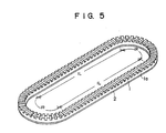
- Figure 5 is a perspective view illustrating a vibration member wherein a piezo electric element 2 including an array of driving piezo electric elements for exciting the pair of standing waves having the phase relationship mentioned above are glued and secured on the back of the elastic body 1 of an elliptic running track shape which consists of straight portions 1L and arcuate portions 1R.
- Figures 6 and 7 are the views illustrating the states of standing waves produced on the elastic body 1. Both Figures 6 and 7 use contour lines to show how the displacements occur in the elastic body plane in its vertical direction. The solid lines indicate the displacement [0], which forms a node of vibration (a nodal line). Each line number corresponds to its altitude: [10] denotes a maximum in the positive direction displacement (peak) while [1] denotes a minimum in the negative displacement (bottom).
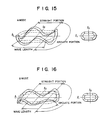
- a vibration member of a running track form when excited, exhibits a pair of standing wave vibrating modes that are symmetrical to the l1 axis and l2 axis as shown in Figs. 15 and 16.
- Figure 15 shows the standing wave vibration mode that is produced by one array of the piezo electric elements. (This mode is called “A vibration mode” hereafter.)
- Figure 16 shows another standing wave vibration mode that is produced by the other array of the piezo electric elements. (This mode is called “B vibration mode” hereafter.)
- the fourth order vibration wave are shown in Figure 15 and Figure 16.
- the positions of the antionodes and nodes for the A vibration mode are different to those of the antinodes and nodes for the B mode, a degree of contributions to each mode by the rigidity of both the straight portion and the arcuate portion of the elastic body is subject to variations, whereby the pair of vibration modes are produced that have different wavelengths, amplitudes and torsional amounts.
- the natural frequencies of these two modes generally do not match.
- the wavelength becomes relatively long and one wave in the wavelength of vibrating waves spreads wide over both the straight and arcuate portions, thus causing the natural frequencies of each vibration mode to become further apart.
- the radius is 3mm and the outside diameter is 7mm for the arcuate portion.
- the length is 20mm and the width is 4mm for the straight portion.
- the thickness is 2mm for the vibrator made of stainless steel (SUS).
- the natural frequencies in this case are 153 KHz in Figure 8, and 136 KHz in Figure 9.
- One aspect of this invention is to provide a vibration wave driven motor of an elliptic form wherein the generation of travelling vibration waves can be assured even in a small radius at the arcuate portions.
- Another aspect of this invention is to provide a vibration wave driven motor of an elliptic form that allows low order travelling vibration waves to be set at discretion.
- One aspect of this invention relates to its feature that with the elastic body of an elliptic shape where different degrees of stiffness or rigidity are available with the arcuate portions and the straight portions, the ratio between the strain energy and the vibration energy that part in the generation of the natural frequency for the A vibration mode is virtually matched to that ratio for the B vibration mode, thus enabling the matching of frequencies for both A and B modes.
- the natural frequency is assumed as "f";
- the contributions ratios of the strain energy and the kinetic energy are made equal to either the straight portion and arcuate portion in the elastic member of the elliptical shape.
- a feature of another embodiment of this invention is that the shape was arranged so as to match both values of K/M, which represents an amount proportional to the value obtained by dividing the strain energy sum by the square sum of vibrating amplitude.
- Figures 1A through 4 show the first embodiment of a vibration wave driven motor of this invention.
- Figure 1A is a cross sectional view, and 1B is a top view.
- Figure 2 is a perspective view of the elastic body which is shown in Figures 1A and 1B.
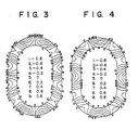
- Figures 3 and 4 are drawings illustrating the displacement of the elastic body which is shown in Figures 1A and 1B.
- Figure 5 is a perspective view of the elastic body which has a large radius in the arcuate portions.
- Figures 6 and 7 are drawings illustrating the displacement of the elastic body which is shown in Figure 5.
- Figures 8 and 9 are drawings illustrating the displacement of the elastic body of the conventional vibration wave driven motor.
- Figures 10 and 11 are drawings illustrating the displacement of the elastic body in the second embodiment.
- Figures 12 and 13 are drawings showing the displacement of the elastic body in the third embodiment.
- Figure 14 is a drawing showing straight portions and arcuate portions of the elastic body.
- Figures 15 and 16 are conceptual drawings illustrating the vibration states of the elastic body
- FIGS 1A through 4 show one embodiment wherein a vibration wave driven motor of this invention is used as a driving source in a printer of bubble jet type.
- Such a printer using a bubble jet method as mentioned above is outlined in U.S. Patent 4,723,129 and 4,740,796 and is described briefly as follows: At least one driving signal, capable of producing a sharp temperature increase in excess of nuclear boiling and also matching one piece of recording information is impressed on each electro-thermal transducer placed pairing with a sheet and a liquid path wherein liquid (ink) is stored. This signal creates thermal energy over the electro-thermal transducer and produces thin film boiling on the heat acting surface of a recording head, hereby producing one bubble to one driving signal inside the liquid (ink). The growth and shrinkage of this air bubble emits the liquid (ink) from a discharge opening, whereby at least one droplet is created. Said droplet sprayed over a sheet of paper creates a character.
- the printer employing this method is generally called a bubble jet printer.
- Figs. 1A and 1B are examples where a linear vibration wave driven motor is used as a vibration wave driven motor.
- the elastic body 1 of an elliptic shape shown in Figure 2 is used as a movable member.
- 10 is a base plate that is secured to the printer's member (which is not shown in the Figure).
- 9 are guide members that are set on both sides of said base plate 10 and have guide grooves of U shape.
- 8 is a stator fixed to said base plate 10 to form a rail.
- 4 is a movable member that is supported movably between both said guide members 9, and fixed to an elastic body 1 via a supporting plate 6 (which will be explained later) such that it can be moved by said elastic body 7.
- a head is established at the right end of said same member 4 in order to print characters on a cut sheet (which is not shown in the Figure).
- the elastic body 1 of the present embodiment having characteristic described above produces standing waves of six order with small distortion in the straight portion, which is a driving portion. Also each natural frequency of the vibrating bodies become approximately equal in association with the two vibration modes with a positional phase shift of 1/4 wavelength.
- Figures 10 and 11 show a second embodiment.
- the sizes of the elastic member are the same as the case in Figures 8 and 9 except that the length of the elastic body in the straight portion is 7mm.
- the number of the wave in the arcuate portion is small, namely 0.6.
- each natural frequency of the vibration members for each vibration mode is substantially the same, thus generating travelling vibration waves over the vibration members.
- Figures 12 and 13 show the third embodiment.
- the sizes of the elastic are the same as the case in Figures 8 and 9 except that the length of the elastic body in the straight portion is 87mm.
- the number of the wave in the arcuate portion is small, namely 0.4.
- the vibration wave driven motor of this invention as hitherto described in detail, of the elastic body consisting of straight portions and arcuate portions, the following effects can be realized because the virtual matching is achieved of the ratios K/M in association with each mode of A and B and as a result of this, the natural frequencies in relation to each vibration mode also come to virtually equal.
- the vibration members 1 and 2 move over the stator 8.
- This invention is also applicable to an apparatus where the vibrating members 1 and 2 are fixedly arranged at a predetermined position and a transporting member such as a sheet is placed over said vibrating members so that said transporting means can be transferred by the travelling vibration waves.
Landscapes
- General Electrical Machinery Utilizing Piezoelectricity, Electrostriction Or Magnetostriction (AREA)
Applications Claiming Priority (2)
| Application Number | Priority Date | Filing Date | Title |
|---|---|---|---|
| JP2088083A JP2993702B2 (ja) | 1990-04-02 | 1990-04-02 | 振動波駆動装置 |
| JP88083/90 | 1990-04-02 |
Publications (2)
| Publication Number | Publication Date |
|---|---|
| EP0450919A1 true EP0450919A1 (de) | 1991-10-09 |
| EP0450919B1 EP0450919B1 (de) | 1997-03-05 |
Family
ID=13932975
Family Applications (1)
| Application Number | Title | Priority Date | Filing Date |
|---|---|---|---|
| EP91302891A Expired - Lifetime EP0450919B1 (de) | 1990-04-02 | 1991-04-02 | Vibrationswellenbetriebener Motor |
Country Status (4)
| Country | Link |
|---|---|
| US (1) | US5128580A (de) |
| EP (1) | EP0450919B1 (de) |
| JP (1) | JP2993702B2 (de) |
| DE (1) | DE69124814T2 (de) |
Cited By (1)
| Publication number | Priority date | Publication date | Assignee | Title |
|---|---|---|---|---|
| EP0600485A1 (de) * | 1992-12-03 | 1994-06-08 | Canon Kabushiki Kaisha | Stutzvorrichtung für vibrationsgetriebenen Antrieb |
Families Citing this family (20)
| Publication number | Priority date | Publication date | Assignee | Title |
|---|---|---|---|---|
| US5428260A (en) * | 1990-08-03 | 1995-06-27 | Canon Kabushiki Kaisha | Vibration driven motor |
| JPH0564467A (ja) * | 1991-09-05 | 1993-03-12 | Canon Inc | 振動波リニアモーター |
| JPH066986A (ja) * | 1992-06-17 | 1994-01-14 | Canon Inc | 振動波モーター及びその製造方法 |
| US5596241A (en) * | 1993-01-18 | 1997-01-21 | Canon Kabushiki Kaisha | Vibration wave driven linear-motor or printer |
| JP3155109B2 (ja) * | 1993-01-22 | 2001-04-09 | キヤノン株式会社 | 振動波駆動装置およびプリンタ装置 |
| GB2315943A (en) * | 1996-08-01 | 1998-02-11 | Paul Michael Wood | Distance measuring system |
| US6628046B2 (en) | 1997-05-27 | 2003-09-30 | Canon Kabushiki Kaisha | Vibration type actuator |
| US6404104B1 (en) | 1997-11-27 | 2002-06-11 | Canon Kabushiki Kaisha | Vibration type actuator and vibration type driving apparatus |
| JP4328412B2 (ja) | 1999-05-14 | 2009-09-09 | キヤノン株式会社 | 振動型アクチュエータおよび振動型駆動装置 |
| JP4726167B2 (ja) * | 2001-03-12 | 2011-07-20 | キヤノン株式会社 | 振動波駆動装置 |
| JP4731723B2 (ja) * | 2001-05-24 | 2011-07-27 | キヤノン株式会社 | 振動波駆動装置の製造方法 |
| JP4027090B2 (ja) * | 2001-12-27 | 2007-12-26 | キヤノン株式会社 | 振動体および振動波駆動装置 |
| JP4756916B2 (ja) * | 2005-05-31 | 2011-08-24 | キヤノン株式会社 | 振動波モータ |
| US9124150B2 (en) * | 2013-07-12 | 2015-09-01 | The Boeing Company | Active-active redundant motor gear system |
| JP2017070115A (ja) | 2015-09-30 | 2017-04-06 | キヤノン株式会社 | 振動型アクチュエータ、振動型アクチュエータの駆動方法、レンズ鏡筒、撮像装置及びステージ装置 |
| US10775681B2 (en) | 2015-11-27 | 2020-09-15 | Canon Kabushiki Kaisha | Ultrasonic motor, drive control system, optical apparatus, and vibrator |
| US10516091B2 (en) | 2015-11-27 | 2019-12-24 | Canon Kabushiki Kaisha | Ultrasonic motor, drive control system, optical apparatus, and vibrator |
| US10451833B2 (en) | 2015-11-27 | 2019-10-22 | Canon Kabushiki Kaisha | Ultrasonic motor, drive control system, optical apparatus, and vibrator |
| US10536097B2 (en) | 2015-11-27 | 2020-01-14 | Canon Kabushiki Kaisha | Ultrasonic motor, drive control system, optical apparatus, and vibrator |
| TWI762671B (zh) * | 2017-12-19 | 2022-05-01 | 日商昕芙旎雅股份有限公司 | 工件搬送裝置 |
Citations (2)
| Publication number | Priority date | Publication date | Assignee | Title |
|---|---|---|---|---|
| EP0169297A2 (de) * | 1984-03-01 | 1986-01-29 | Matsushita Electric Industrial Co., Ltd. | Piezoelektrischer Motor |
| GB2174554A (en) * | 1985-03-29 | 1986-11-05 | Canon Kk | Vibration wave motor |
Family Cites Families (7)
| Publication number | Priority date | Publication date | Assignee | Title |
|---|---|---|---|---|
| CA1127227A (en) * | 1977-10-03 | 1982-07-06 | Ichiro Endo | Liquid jet recording process and apparatus therefor |
| JPS59201685A (ja) * | 1983-04-30 | 1984-11-15 | Canon Inc | 振動波モ−タ |
| JPS61154487A (ja) * | 1984-12-26 | 1986-07-14 | Canon Inc | リニア振動波モ−タ |
| US4739212A (en) * | 1985-07-19 | 1988-04-19 | Matsushita Electric Industrial Co., Ltd. | Ultrasonic motor |
| JPS6277969A (ja) * | 1985-10-02 | 1987-04-10 | Nec Corp | プリンタ装置 |
| JPH02285974A (ja) * | 1989-04-25 | 1990-11-26 | Canon Inc | 振動波モータ |
| JP2669913B2 (ja) * | 1989-12-15 | 1997-10-29 | キヤノン株式会社 | 振動波駆動装置および振動波駆動装置を駆動源とする移動機器 |
-
1990
- 1990-04-02 JP JP2088083A patent/JP2993702B2/ja not_active Expired - Fee Related
-
1991
- 1991-04-02 DE DE69124814T patent/DE69124814T2/de not_active Expired - Fee Related
- 1991-04-02 US US07/679,288 patent/US5128580A/en not_active Expired - Fee Related
- 1991-04-02 EP EP91302891A patent/EP0450919B1/de not_active Expired - Lifetime
Patent Citations (2)
| Publication number | Priority date | Publication date | Assignee | Title |
|---|---|---|---|---|
| EP0169297A2 (de) * | 1984-03-01 | 1986-01-29 | Matsushita Electric Industrial Co., Ltd. | Piezoelektrischer Motor |
| GB2174554A (en) * | 1985-03-29 | 1986-11-05 | Canon Kk | Vibration wave motor |
Cited By (2)
| Publication number | Priority date | Publication date | Assignee | Title |
|---|---|---|---|---|
| EP0600485A1 (de) * | 1992-12-03 | 1994-06-08 | Canon Kabushiki Kaisha | Stutzvorrichtung für vibrationsgetriebenen Antrieb |
| US5484216A (en) * | 1992-12-03 | 1996-01-16 | Canon Kabushiki Kaisha | Supporting device for a vibration driven actuator |
Also Published As
| Publication number | Publication date |
|---|---|
| DE69124814T2 (de) | 1997-06-26 |
| DE69124814D1 (de) | 1997-04-10 |
| JP2993702B2 (ja) | 1999-12-27 |
| US5128580A (en) | 1992-07-07 |
| JPH03289370A (ja) | 1991-12-19 |
| EP0450919B1 (de) | 1997-03-05 |
Similar Documents
| Publication | Publication Date | Title |
|---|---|---|
| EP0450919A1 (de) | Vibrationswellenbetriebener Motor | |
| US5039899A (en) | Piezoelectric transducer | |
| JP4802313B2 (ja) | 圧電振動子の保持装置 | |
| US5101132A (en) | Linear ultrasonic motor | |
| EP0598710B1 (de) | Scwingungswellengetriebene Vorrichtung und Strahldrucker mit eine solchen Vorrichtung | |
| GB2229045A (en) | Ultrasonic linear motor with U-shaped vibrating body | |
| US5852336A (en) | Vibration actuator which effectively transmits micro-amplitude vibrations | |
| KR930009211A (ko) | 초음파 모우터 | |
| EP0437050B1 (de) | Vibrationswellengetriebene Vorrichtung | |
| US5274294A (en) | Vibration wave driven motor | |
| US5041750A (en) | Vibration wave driven apparatus | |
| US5455478A (en) | Vibration wave driven apparatus | |
| JPS62259485A (ja) | 圧電駆動装置 | |
| EP0493941A1 (de) | Tragevorrichtung für vibrationswellenbetriebenen Motor | |
| EP0404158B1 (de) | Bogentransportvorrichtung | |
| JPH01264582A (ja) | 超音波リニアモータ | |
| JPH09117166A (ja) | 超音波モータ | |
| JP3354380B2 (ja) | 静電アクチュエータ | |
| JP3306211B2 (ja) | 超音波アクチュエータ | |
| JPH02202379A (ja) | 平面型超音波アクチュエータ | |
| JPH0552137B2 (de) | ||
| JPS63148877A (ja) | リニア振動波モ−タ | |
| JPS63117674A (ja) | 超音波モ−タ | |
| JPH02219474A (ja) | 平面型超音波アクチュエータ | |
| JPH0331138A (ja) | シート送り装置 |
Legal Events
| Date | Code | Title | Description |
|---|---|---|---|
| PUAI | Public reference made under article 153(3) epc to a published international application that has entered the european phase |
Free format text: ORIGINAL CODE: 0009012 |
|
| AK | Designated contracting states |
Kind code of ref document: A1 Designated state(s): DE FR GB IT |
|
| 17P | Request for examination filed |
Effective date: 19920224 |
|
| 17Q | First examination report despatched |
Effective date: 19940622 |
|
| GRAH | Despatch of communication of intention to grant a patent |
Free format text: ORIGINAL CODE: EPIDOS IGRA |
|
| GRAH | Despatch of communication of intention to grant a patent |
Free format text: ORIGINAL CODE: EPIDOS IGRA |
|
| ITF | It: translation for a ep patent filed | ||
| GRAA | (expected) grant |
Free format text: ORIGINAL CODE: 0009210 |
|
| AK | Designated contracting states |
Kind code of ref document: B1 Designated state(s): DE FR GB IT |
|
| REF | Corresponds to: |
Ref document number: 69124814 Country of ref document: DE Date of ref document: 19970410 |
|
| ET | Fr: translation filed | ||
| PLBE | No opposition filed within time limit |
Free format text: ORIGINAL CODE: 0009261 |
|
| STAA | Information on the status of an ep patent application or granted ep patent |
Free format text: STATUS: NO OPPOSITION FILED WITHIN TIME LIMIT |
|
| 26N | No opposition filed | ||
| REG | Reference to a national code |
Ref country code: GB Ref legal event code: IF02 |
|
| PGFP | Annual fee paid to national office [announced via postgrant information from national office to epo] |
Ref country code: GB Payment date: 20030319 Year of fee payment: 13 |
|
| PGFP | Annual fee paid to national office [announced via postgrant information from national office to epo] |
Ref country code: FR Payment date: 20030422 Year of fee payment: 13 |
|
| PGFP | Annual fee paid to national office [announced via postgrant information from national office to epo] |
Ref country code: DE Payment date: 20030424 Year of fee payment: 13 |
|
| PG25 | Lapsed in a contracting state [announced via postgrant information from national office to epo] |
Ref country code: GB Free format text: LAPSE BECAUSE OF NON-PAYMENT OF DUE FEES Effective date: 20040402 |
|
| PG25 | Lapsed in a contracting state [announced via postgrant information from national office to epo] |
Ref country code: DE Free format text: LAPSE BECAUSE OF NON-PAYMENT OF DUE FEES Effective date: 20041103 |
|
| GBPC | Gb: european patent ceased through non-payment of renewal fee | ||
| PG25 | Lapsed in a contracting state [announced via postgrant information from national office to epo] |
Ref country code: FR Free format text: LAPSE BECAUSE OF NON-PAYMENT OF DUE FEES Effective date: 20041231 |
|
| REG | Reference to a national code |
Ref country code: FR Ref legal event code: ST |
|
| PG25 | Lapsed in a contracting state [announced via postgrant information from national office to epo] |
Ref country code: IT Free format text: LAPSE BECAUSE OF NON-PAYMENT OF DUE FEES Effective date: 20050402 |