EP0451132B1 - Ski - Google Patents
Ski Download PDFInfo
- Publication number
- EP0451132B1 EP0451132B1 EP91890051A EP91890051A EP0451132B1 EP 0451132 B1 EP0451132 B1 EP 0451132B1 EP 91890051 A EP91890051 A EP 91890051A EP 91890051 A EP91890051 A EP 91890051A EP 0451132 B1 EP0451132 B1 EP 0451132B1
- Authority
- EP
- European Patent Office
- Prior art keywords
- ski
- carrier body
- longitudinal direction
- support body
- damping
- Prior art date
- Legal status (The legal status is an assumption and is not a legal conclusion. Google has not performed a legal analysis and makes no representation as to the accuracy of the status listed.)
- Expired - Lifetime
Links
Images


Classifications
-
- A—HUMAN NECESSITIES
- A63—SPORTS; GAMES; AMUSEMENTS
- A63C—SKATES; SKIS; ROLLER SKATES; DESIGN OR LAYOUT OF COURTS, RINKS OR THE LIKE
- A63C5/00—Skis or snowboards
- A63C5/06—Skis or snowboards with special devices thereon, e.g. steering devices
- A63C5/075—Vibration dampers
-
- A—HUMAN NECESSITIES
- A63—SPORTS; GAMES; AMUSEMENTS
- A63C—SKATES; SKIS; ROLLER SKATES; DESIGN OR LAYOUT OF COURTS, RINKS OR THE LIKE
- A63C9/00—Ski bindings
Definitions
- the invention relates to a ski with integrated parts for fixing binding parts.
- Integrated parts for the fixing of binding parts have already been proposed in the form of screw sleeves arranged recessed in the ski.
- prefabricated anchoring points or anchoring bearings for binding parts that have already been introduced during ski production are in no way suitable for keeping the binding parts at a precisely defined distance from one another after they have been attached to the ski if the ski undergoes bending during skiing.
- the measurable lengthening or shortening of the effective distance of the front binding part from the rear binding part when the ski bends leads to a distortion of the triggering forces and can lead to undesired incorrect triggering of bindings.
- the invention now aims to establish a ski of the type mentioned above with integrated parts To create binding parts with which the torsion properties can be influenced in an adjustable manner in the region of the binding and at the same time the release properties of a binding remain largely unaffected even with different ski deflections.
- the invention further aims to provide the possibility, in such a device, of connecting the binding elements in a manner to the integrated parts for the fixing of binding parts, which can reliably dampen impacts that act vertically on the ski surface.
- the ski according to the invention essentially consists in that the ski is rigidly connected to an essentially plate-shaped support body which extends in the longitudinal direction of the ski in an area of the support body lying between the ends pointing in the longitudinal direction of the ski, that the support body is rigid in the outside of the with the ski connected area extending in the longitudinal direction of guide rails or grooves for fixing the binding parts and that the ends of the supporting body pointing in the longitudinal direction of the ski are arranged at a distance from the top of the ski upper belt.
- the support body Due to the essentially central definition of the support body, the support body itself can be decoupled from forces acting on the ski, and conversely, release forces, such as those which act on the binding parts, do not reach the ski body directly.
- the decoupling of the binding from the ski which can be achieved in this way makes it possible to define the desired release forces of the binding more precisely, while excessive safety reserves for the release of a binding and thus in many cases premature release of the binding can be avoided.
- the design is advantageously made such that the support body is located outside the area rigidly connected to the ski Interposition of a damping material is connected to the ski or the upper flange of the ski.
- a damping material is connected to the ski or the upper flange of the ski.
- Such an arrangement of the damping material has the consequence that the elasticity and thus the bending behavior of the ski in the longitudinal direction of the ski is in no way impaired, the fixing in the central area ensuring the desired stiffening against torsional forces.
- a perfect damping of vertical impacts is ensured and a secure and largely indestructible connection is established by fixing the support body in the central area of the support body of the supporting body with the ski.
- the design is advantageously made such that the support body has projections or recesses in the region of the guide rails or grooves for locking binding parts against displacement in the longitudinal direction of the ski.
- the design according to the invention can, as is the case in a preferred development, be made in such a way that the support body is arranged below the surface cover layer, in particular below a ski decor surface film. In this way, an integration of the support body and the damping element into the ski construction during manufacture is achieved, which maintains the desired elasticity in the longitudinal direction, while at the same time ensuring a high degree of security against destruction.
- the support body can advantageously have profiles that run transversely to the longitudinal direction of the ski, the design being made in a particularly advantageous manner so that the support body in the central region is one of the Thickness of the damping material has a corresponding recess and is rigidly connected to the ski in the recessed area.
- Such a lowering of the profile in the central area enables a perfect connection of the support body to the upper flange of the ski, the damping material likewise being able to be at least partially embedded in the surface of the ski.
- such a design is particularly well suited for the arrangement of a guide groove for the insertion of binding parts, the binding parts being able to be inserted into the guide groove in the longitudinal direction of the ski, starting from the recessed area of the supporting body.
- Such Formation of the support body increases the torsional rigidity due to the folds in the area of the profile lowering, the torsion properties being able to be varied to a great extent by the shape and extent of the transverse profiles.
- the construction can also be made such that the recessed area of the support body is filled with a correspondingly pressure-resistant filler, the rigid connection of the support body with the advantage Ski top belt can be designed as an adhesive.
- a guide rail is advantageously used to hold binding parts.
- the middle part of the support body can be screwed to the ski, in particular the upper flange of the ski, such a screw connection not having to absorb shear forces when the ski bends.
- a uniform design of the surface with simultaneous additional securing of the damping element is ensured in that the support body is arranged below the surface cover layer, the design advantageously being such that the support body is arranged flush with the surface layer or film in a recess on the top of the ski is.
- the surface film in front of and behind the carrier body is advantageously cut or cut transversely to the longitudinal direction of the ski, with Advantage of the transition from the undamped areas of the ski into the area of the support body is flat and without pronounced edges, in order to avoid overloading here.
- the training is advantageously made so that the free ends of the Support body are formed at an acute angle to the ski.
- Carrier bodies made of metal, in particular aluminum, are advantageously used, and in order to improve the adhesive connection and for easier processing, the design can be such that the carrier body is rigidly connected to the upper chord with the interposition of at least one layer of glass fiber-reinforced plastic.
- the entire inner surface of the support body can have a layer of glass fiber reinforced plastic, so that a simple adhesive bond to the damping material is also possible.
- the design can advantageously be made such that damping elements of different hardness or rigidity are arranged next to one another in the longitudinal direction of the ski, transversely to the longitudinal direction of the ski, in which If the damping elements arranged next to one another in the longitudinal direction of the ski can be welded or glued in a particularly advantageous manner to the layer made of glass fiber reinforced plastic on the inside of the carrier body.
- the thickness of the damping element should advantageously be between 2 and 12 mm.
- the design is preferably such that the damping material runs essentially transversely to the longitudinal direction of the ski, in particular bores, wherein the recesses can either remain empty or elements, in particular rods, of different hardness and flexibility properties can be inserted into the recesses.
- the design according to the invention allows the elastic movement of the ski to the full extent without being impaired by the damping element and leads to a rigid fixing of the supporting body and the damping element which cannot be disassembled during operation, with the risk of detachment of the supporting body or the damping element in the event of strong deflections of the Skis do not exist.
- a reproducible, reliable bond can only be ensured in the case of the determination already made during manufacture, in which the rigid bond is to be made directly to the upper belt of the ski.
- the desired torsional properties can be set, with an additional possibility of varying the torsional stabilities in the choice of the profiling of the support body.
- Glass-fiber-reinforced plastic on the inside of such support bodies can on the one hand facilitate the secure gluing and on the other hand take over the function of reinforcement laminates, which can likewise increase the torsional stability and reduce the risk of tearing off bonds which can be attached to such damping elements.
- Prefabricated anchoring points such as e.g. Screw bushings or the like, for the determination of bindings are integrated.
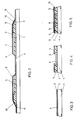
- FIG. 1 shows a partial perspective view of a ski according to the invention
- 2 shows a section along the line II-II of Figure 1
- 3 shows a section along the line III-III of Figures 1 and 2
- 4 shows a section along the line IV-IV of Figures 1 and 2
- 5 shows a section through a modified embodiment in a representation analogous to FIG. 3
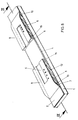
- 6 shows a perspective partial view of a modified embodiment in a representation analogous to FIG. 1
- 7 shows a section along the line VII-VII of Figure 6
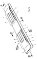
- 8 shows a perspective partial view of a further embodiment of a ski according to the invention in a representation analogous to FIGS.
- FIG. 14 a further modified embodiment in a representation similar to FIG. 10 with recesses in the damping material for adjusting the flexibility.
- FIG. 1 to 4 show a first embodiment of a ski 1, the top of which is covered by a surface cover layer, for example a ski decor surface film 2.
- a surface cover layer for example a ski decor surface film 2.
- an essentially plate-shaped support body 3 for example made of aluminum, which is directly rigidly connected to the ski in a central region 4, for example by gluing and optionally by an additional screw connection.
- the ends of the support body 3 which point in the longitudinal direction of the ski and which are rigidly connected to the ski 1 in the longitudinal direction of the ski, are arranged at a distance from the top of the ski upper belt 7 and connect to the ski with the interposition of damping material 5, in particular elastomeric damping material.
- guide grooves 6 are provided, which extend over an area of the areas 8 of the ski belt 7 that are spaced apart Extend support body 3.
- the depth of the offset region 4 of the profile forming the support body 3 corresponds essentially to the height or thickness of the damping material 5 and exceeds the depth of the guide grooves 6.
- the gluing or rigid connection of the support body 3 to the ski 1 and in particular to its upper flange 7 can take place with the interposition of a layer made of glass fiber reinforced plastic.
- a continuous GRP layer can also be provided on the surface of the support body 3 facing the ski 1.
- damping elements of different hardness can be arranged next to one another transversely to the longitudinal direction of the ski, as is indicated in FIG. 4 by the outer damping elements 5 and inner damping elements 9 .
- the free ends 10 of the support body 3 run at an acute angle to the surface of the ski 1 or its upper flange 7 and end in the unloaded position of the ski at a short distance from the surface of the upper flange 7.
- the surface cover layer is cut or cut directly in front of and behind the support body transversely to the longitudinal direction of the ski, as is schematically indicated by 11.
- the regions 8 of the support body 3 which are spaced apart from the ski top belt 7 have recesses or projections 12 in the region of the guide groove 6 for locking binding parts (not shown in more detail) in different positions.
- grooves 13 extend in the longitudinal direction Inclusion of binding parts provided.
- an S-shaped transition area 14, seen in cross-section, is provided between the area 4 rigidly connected to the ski top belt or the ski and the areas 8 consisting of the ski top belt, with these being S-shaped Crank allows greater elasticity.
- a multi-part support body is provided, the middle area 4 being rigidly connected to the ski 1 or the upper belt 7 and spaced from the ski surface or from the ski upper belt 7 lying areas 8 are connected in a sandwich connection by the interposition of elements 15 made of a correspondingly stable material with the area 4 of the support body 3.
- the regions 8 of the support body 3 in turn have guide grooves 6 running in the longitudinal direction of the ski and extending over part of the length of the regions 8 for receiving binding parts (not shown in any more detail).
- guide rails 16 are provided, onto which binding parts, not shown, can be pushed.
- the guide rails 16 in turn have recesses or projections 17 for fixing binding parts at different axial distances from one another.
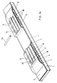
- recesses or bores 18 are provided in the damping material 5 which run essentially transversely to the longitudinal direction of the ski and which, depending on their number and arrangement, result in an increase in the elasticity of the supporting body 3 and the damping material 5.
- rods 19 of corresponding cross-section can be inserted into the recesses or bores 18, with the use of rods of different material properties being able to adapt to the desired flexibility behavior of the damping material 5.
- the vibration behavior of the ski and the binding can be decoupled so that shocks or impacts from the ski, for example are completely intercepted by the damping elements and are not transferred into the binding or into the foot of the skier.
- an essentially flat plate-shaped support body can be provided, in particular when using guide rails, which in turn is only connected to the upper flange 7 in the central region 4, while the upper flange is formed in the regions 8 adjoining in the longitudinal direction of the ski can, in order to provide a distance between the top of the upper flange or the ski and the regions 8 of the support body 3 not connected to the ski.
- the guide grooves 6 or guide rails 16 are designed in such a way that it is possible to insert or insert or insert suitable ski binding jaws, heel and brake parts along the ski axis.
Landscapes
- Vibration Dampers (AREA)
- Lubricants (AREA)
- Transition And Organic Metals Composition Catalysts For Addition Polymerization (AREA)
- Laminated Bodies (AREA)
- Polyesters Or Polycarbonates (AREA)
- Fittings On The Vehicle Exterior For Carrying Loads, And Devices For Holding Or Mounting Articles (AREA)
- Medicines That Contain Protein Lipid Enzymes And Other Medicines (AREA)
Claims (19)
- Ski avec pièces intégrées pour la fixation de pièces de liaison, caractérisé en ce que le ski (1) est relié de façon rigide à un élément porteur (3) essentiellement en forme de plaque qui s'étend dans le sens de la longueur du ski, dans une zone (4) de l'élément porteur (3) située entre les extrémités dirigées dans le sens de la longueur du ski, en ce que l'élément porteur (3) présente, en dehors de la zone reliée de façon rigide avec le ski (1), des rails ou rainures de guidage (6, 13, 16) qui sont disposés dans le sens de la longueur du ski et qui sont destinés à fixer les pièces de liaison et en ce que les extrémités (10) de l'élément porteur (3) dirigées dans le sens de la longueur du ski sont disposées à distance de la face supérieure de la semelle supérieure (7) du ski.
- Ski selon la revendication 1, caractérisé en ce que l'élément porteur (3), en dehors de la zone (4) reliée de façon rigide au ski (1), est relié au ski ou à la semelle supérieure (7) du ski avec intercalation d'un matériau amortisseur (5, 9).
- Ski selon la revendication 1 ou 2, caractérisé en ce que l'élément porteur (3) présente, dans la zone des rails de guidage ou des rainures de guidage (6, 13, 16), des saillies ou des évidements (12, 17) destinés à verrouiller les pièces de liaison pour les protéger contre le déplacement dans le sens de la longueur du ski.
- Ski selon la revendication 1, 2 ou 3, caractérisé en ce que l'élément porteur (3) est disposé sous la couche de recouvrement superficielle (2), en particulier sous une feuille superficielle décorative du ski.
- Ski selon l'une des revendications 1 à 4, caractérisé en ce que l'élément porteur (3) présente, dans la zone médiane (4), une dépression correspondant pour l'essentiel à l'épaisseur du matériau amortisseur (5, 9) et est relié de façon rigide au ski (1) dans la zone en dépression (4).
- Ski selon une des revendications 1 à 5, caractérisé en ce que la zone en dépression (4) de l'élément porteur (1) est remplie d'un matériau de remplissage résistant à la pression.
- Ski selon l'une des revendications 1 à 6, caractérisé en ce que la liaison rigide de l'élément porteur (3) avec la semelle supérieure de ski (7) est réalisée sous la forme d'un collage.
- Ski selon l'une des revendications 1 à 7, caractérisé en ce que les extrémités libres (10) de l'élément porteur (3) sont réalisées de façon à former un angle aigu avec le ski (1).
- Ski selon l'une des revendications 1 à 8, caractérisé en ce que l'élément porteur (3) est relié de façon rigide à la semelle supérieure (7) avec intercalation d'une couche (8) en matière plastique renforcée de fibres de verre.
- Ski selon l'une des revendications 1 à 9, caractérisé en ce que l'élément porteur (3) est réalisé en métal, en particulier en aluminium.
- Ski selon l'une des revendications 1 à 10, caractérisé en ce que l'élément porteur (3) présente, sur sa face intérieure tournée vers le ski (1), au moins une couche (8) en matière plastique renforcée de fibres de verre.
- Ski selon l'une des revendications 1 à 11, caractérisé en ce que l'élément porteur (3) est disposé dans un évidement de la face supérieure du ski de façon à affleurer avec la couche ou la feuille (2) superficielle.
- Ski selon l'une des revendications 1 à 12, caractérisé en ce que, à l'avant et à l'arrière de l'élément porteur (3), la feuille superficielle (2) est séparée ou coupée transversalement au sens de la longueur du ski.
- Ski selon l'une des revendications 1 à 13, caractérisé en ce que, transversalement au sens de la longueur du ski, des éléments amortisseurs (5, 9) de différentes duretés ou de différentes rigidités sont disposés les uns à côté des autres dans le sens de la longueur du ski.
- Ski selon l'une des revendications 1 à 14, caractérisé en ce que l'élément porteur (3) présente des profilages s'étendant transversalement au sens de la longueur du ski.
- Ski selon l'une des revendications 1 à 15, caractérisé en ce que la partie médiane (4) de l'élément porteur (8) est collée et vissée au ski (1).
- Ski selon l'une des revendications 1 à 16, caractérisé en ce que l'élément amortisseur (5, 9) est réglé avec des duretés Shore (A) de 30 à 90.
- Ski selon l'une des revendications 1 à 17, caractérisé en ce que l'épaisseur des éléments amortisseurs (5, 9), mesurée perpendiculairement à la surface du ski, représente 2 à 12 mm.
- Ski selon l'une des revendications 2 à 18, caractérisé en ce que l'élément amortisseur (5, 9) présente des évidements (12), en particulier des alésages, s'étendant sensiblement transversalement au sens de la longueur du ski.
Applications Claiming Priority (4)
| Application Number | Priority Date | Filing Date | Title |
|---|---|---|---|
| AT0082090A AT398039B (de) | 1990-04-05 | 1990-04-05 | Ski |
| AT820/90 | 1990-04-05 | ||
| AT188890 | 1990-09-17 | ||
| AT1888/90 | 1990-09-17 |
Publications (3)
| Publication Number | Publication Date |
|---|---|
| EP0451132A2 EP0451132A2 (fr) | 1991-10-09 |
| EP0451132A3 EP0451132A3 (en) | 1991-11-06 |
| EP0451132B1 true EP0451132B1 (fr) | 1994-07-27 |
Family
ID=25594010
Family Applications (2)
| Application Number | Title | Priority Date | Filing Date |
|---|---|---|---|
| EP91890051A Expired - Lifetime EP0451132B1 (fr) | 1990-04-05 | 1991-03-19 | Ski |
| EP91890050A Expired - Lifetime EP0454655B1 (fr) | 1990-04-05 | 1991-03-19 | Ski |
Family Applications After (1)
| Application Number | Title | Priority Date | Filing Date |
|---|---|---|---|
| EP91890050A Expired - Lifetime EP0454655B1 (fr) | 1990-04-05 | 1991-03-19 | Ski |
Country Status (6)
| Country | Link |
|---|---|
| US (2) | US5143395A (fr) |
| EP (2) | EP0451132B1 (fr) |
| JP (2) | JPH05200139A (fr) |
| AT (2) | ATE115876T1 (fr) |
| CA (2) | CA2039831A1 (fr) |
| DE (2) | DE59103953D1 (fr) |
Cited By (1)
| Publication number | Priority date | Publication date | Assignee | Title |
|---|---|---|---|---|
| AT407712B (de) * | 1995-08-14 | 2001-05-25 | Atomic Austria Gmbh | Brettartiges gleitgerät, insbesondere schi mit einem tragkörper |
Families Citing this family (54)
| Publication number | Priority date | Publication date | Assignee | Title |
|---|---|---|---|---|
| WO1992022361A1 (fr) * | 1991-06-17 | 1992-12-23 | Trimble & Co., Inc. | Bloc pour fixation de ski |
| FR2684011B1 (fr) * | 1991-11-25 | 1994-01-07 | Rossignol Sa Skis | Planche de glisse pourvue d'un dispositif d'amortissement des vibrations. |
| FR2698013B1 (fr) * | 1992-11-19 | 1994-12-16 | Rossignol Sa | Dispositif de montage d'une chaussure sur un ski alpin. |
| US5344167A (en) * | 1993-04-21 | 1994-09-06 | Strouth John E | Ski sled |
| FR2705905B1 (fr) * | 1993-06-02 | 1995-07-07 | Rossignol Sa | Ski à profil perfectionné. |
| IT1265144B1 (it) * | 1993-07-12 | 1996-10-31 | Claudio Bambieri | Dispositivo per il montaggio e lo smontaggio rapido degli attacchi sugli sci |
| FR2708476B1 (fr) * | 1993-08-06 | 1995-09-08 | Rossignol Sa | Dispositif pour le montage d'une fixation de chaussure sur un ski alpin. |
| FR2713499B1 (fr) * | 1993-12-07 | 1996-01-19 | Rossignol Sa | Plaque pour le montage sur un ski alpin d'une fixation pour chaussure. |
| AT405138B (de) * | 1994-01-28 | 1999-05-25 | Varpat Patentverwertung | Dämpfungsvorrichtung für kupplungsteile, z.b. einen vorder- und/oder hinterbacken |
| DE4403151A1 (de) * | 1994-02-03 | 1995-08-10 | Marker Deutschland Gmbh | Vorrichtung zur Veränderung der Bodendruckverteilung eines Skis |
| JPH10500339A (ja) * | 1994-05-21 | 1998-01-13 | ペーター ゲッツフリート | スキーの縦方向湾曲を適宜制御するための装置 |
| JP2822151B2 (ja) * | 1994-07-14 | 1998-11-11 | 美津濃株式会社 | 防振性を有するスキー |
| FR2726193B1 (fr) * | 1994-10-28 | 1996-12-06 | Rossignol Sa | Engin de glisse sur neige, tel que ski alpin, ski de fond, monoski, surf |
| FR2734490B1 (fr) * | 1995-05-22 | 1997-07-04 | Rossignol Sa | Planche de glisse sur neige comportant une plateforme de reception et de surelevation des fixations de la chaussure |
| US5775715A (en) * | 1995-08-01 | 1998-07-07 | K-2 Corporation | Piezoelectric damper for a board such as a snow ski or snowboard |
| US6095547A (en) * | 1995-08-01 | 2000-08-01 | K-2 Corporation | Active piezoelectric damper for a snow ski or snowboard |
| USD387408S (en) * | 1995-10-27 | 1997-12-09 | Richard Floreani | Transparent sliding device dampener |
| US5810370A (en) * | 1996-03-04 | 1998-09-22 | Covert; Richard P. | Snow board binding |
| US5909894A (en) * | 1997-01-02 | 1999-06-08 | K-2 Corporation | Snowboard binding |
| US5906388A (en) * | 1997-01-14 | 1999-05-25 | Quiksilver, Inc. | Footwear mounting system |
| FR2769236B1 (fr) * | 1997-10-03 | 2000-02-04 | Salomon Sa | Cale d'amortissement pour dispositif de retenue d'une chaussure sur une planche de glisse destinee a la pratique du surf sur neige, et dispositif muni d'une telle cale |
| US5884934A (en) * | 1997-12-05 | 1999-03-23 | K-2 Corporation | Ski having binding mounting portion for angled boot orientation |
| US6102427A (en) * | 1997-12-05 | 2000-08-15 | K-2 Corporation | Ski binding lifter having internal fastener retention layer |
| FR2775437B1 (fr) | 1998-02-27 | 2000-05-19 | Salomon Sa | Dispositif interface entre un ski et des elements de retenue d'une chaussure sur le ski |
| FR2781686B1 (fr) * | 1998-07-31 | 2000-12-15 | Salomon Sa | Planche de glisse pour la pratique du ski alpin ou du surf de neige |
| US6131939A (en) * | 1998-08-17 | 2000-10-17 | Fels Canadian Ski Company Ltd. | Snow ski having slidingly interconnected upper and lower ski sections |
| FR2785823B1 (fr) * | 1998-11-13 | 2001-03-02 | Salomon Sa | Engin de glisse comprenant un dispositif d'interface de fixations relie a un ski |
| US6267402B1 (en) * | 1999-03-30 | 2001-07-31 | Nitinol Technologies, Inc. | Nitinol ski structures |
| CZ290978B6 (cs) * | 1999-05-14 | 2002-11-13 | Milan Trnka | Spojovací blok vázání |
| FR2800622B1 (fr) * | 1999-11-05 | 2002-02-08 | Salomon Sa | Planche de glisse destinee a la pratique du surf sur neige |
| US6371506B1 (en) * | 2000-08-04 | 2002-04-16 | Denicola James A. | Wedge-shaped shims for free heel skis |
| US6715773B2 (en) | 2001-01-09 | 2004-04-06 | K-2 Corporation | Adjustable damping pads for snowboard bindings |
| US6916035B2 (en) | 2001-01-23 | 2005-07-12 | Russell A. Houser | Athletic devices and other devices with superelastic components |
| FR2820335B1 (fr) * | 2001-02-02 | 2003-03-07 | Rossignol Sa | Plaque interface destinee a etre solidarisee a la face superieure d'un ski |
| DE10131138A1 (de) * | 2001-06-28 | 2003-01-16 | Rottefella As Klokkarstua | Vorrichtung zur Befestigung einer Skibindung oder deren Teile an einem Ski |
| FR2827786B1 (fr) * | 2001-07-27 | 2003-09-12 | Rossignol Sa | Ski alpin |
| DE20221919U1 (de) * | 2002-04-11 | 2009-04-23 | Marker Deutschland Gmbh | Basisplatte bzw. -anordnung einer Ski- oder Snowboardbindung |
| DE10254063A1 (de) * | 2002-11-19 | 2004-06-03 | InnoTec Ges. zur Entwicklung innovativer Technologien Uwe Emig, Prof. Reinhold Geilsdörfer, Markus Gramlich GbR | Alpinski |
| DE10254471A1 (de) | 2002-11-21 | 2004-06-03 | Madsus A/S | Ski mit Bindungs-Montagehilfe, Verfahren zur Herstellung eines solchen Ski sowie entsprechende Montagehilfe |
| AT500252B1 (de) * | 2003-03-07 | 2008-12-15 | Tyrolia Technology Gmbh | Gleitbrett, insbesondere ski |
| FR2864451B1 (fr) * | 2003-12-24 | 2006-01-27 | Skis Dynastar | Ski |
| DE102004024881A1 (de) * | 2004-05-19 | 2005-07-14 | Rottefella As | Langlauf- oder Telemarkbindung |
| USD532475S1 (en) | 2004-12-16 | 2006-11-21 | Rottefella As | Mounting plate for a ski binding |
| DE202004019710U1 (de) * | 2004-12-21 | 2005-04-07 | Blizzard Sport Ges M B H | Gleitbrett, insbesondere Alpinski oder Snowboard |
| ATE426439T1 (de) * | 2005-01-10 | 2009-04-15 | Rottefella As | Ski oder dergleichen schneegleitgerat mit bindungs-montagehilfe |
| RU2380130C2 (ru) * | 2005-01-10 | 2010-01-27 | Роттефелла Ас | Лыжа или аналогичный снаряд для скольжения по снегу со вспомогательным приспособлением для установки крепления |
| US20080127523A1 (en) * | 2005-02-11 | 2008-06-05 | Rottefella As | Outsole for a Cross-Country Ski Boot or Telemark Boot and Cross-Country Ski Boot or Telemark Boot Having Such an Outsole |
| SI22083B (sl) * | 2005-07-18 | 2009-12-31 | Elan, D.O.O. | Smučka ali snežna deska z izboljšano torzijsko togostjo |
| FR2897274B1 (fr) * | 2006-02-10 | 2009-07-10 | Salomon Sa | Dispositif d'interface pour une planche de glisse |
| US7823905B2 (en) * | 2006-03-17 | 2010-11-02 | William J Ritter | Splitboard bindings |
| US9022412B2 (en) | 2006-03-17 | 2015-05-05 | William J Ritter | Splitboard bindings |
| EP2111900B1 (fr) * | 2008-04-25 | 2011-12-14 | Rottefella AS | Cartouche de ressort pour fixation de ski |
| US9126099B2 (en) | 2013-01-27 | 2015-09-08 | William J Ritter | Boot binding system with foot latch pedal |
| WO2016172700A1 (fr) * | 2015-04-24 | 2016-10-27 | Staker Rodney L | Montage de base pour fixer un ensemble de fixation de ski à des skis |
Family Cites Families (22)
| Publication number | Priority date | Publication date | Assignee | Title |
|---|---|---|---|---|
| AT37145B (de) | 1907-05-01 | 1909-05-10 | Charles Henry Krueger | Rettungsvorrichtung. |
| US2318184A (en) * | 1936-01-18 | 1943-05-04 | Walter H Liebman | Laminated sheet and method of producing same |
| US3260532A (en) * | 1965-04-02 | 1966-07-12 | Johan G F Heuvel | Ski binding mounting and runner construction |
| US3567237A (en) * | 1968-10-29 | 1971-03-02 | Line Co A | Ski covering |
| DE2259375A1 (de) * | 1972-12-04 | 1974-06-12 | Heinrich Bellan | Verfahren und vorrichtung zur verbesserung der lenkfaehigkeit von schier |
| DE2461461A1 (de) * | 1974-12-24 | 1976-07-08 | Schloemann Siemag Ag | Kunststoff-ski |
| DE2535847A1 (de) * | 1975-08-12 | 1977-02-24 | Lifka | Zusatzeinrichtung fuer die verbindung von ski und bindung bei o- und x- beinigkeit |
| FR2329241A1 (fr) * | 1975-10-30 | 1977-05-27 | Ato Batiment | Baignoire |
| DE2601951C2 (de) * | 1976-01-20 | 1982-04-22 | Hans 8000 München Meyer | Ski |
| DE2634748A1 (de) * | 1976-01-20 | 1978-02-09 | Hans Meyer | Ski mit federbrett |
| FR2340749A1 (fr) * | 1976-02-10 | 1977-09-09 | Salomon & Fils F | Dispositif de reglage en longueur pour fixations de ski |
| US4409287A (en) * | 1981-06-09 | 1983-10-11 | Harrison Thomas B | Ski protective device |
| CH671887A5 (fr) * | 1982-03-25 | 1989-10-13 | Brosi Bettosini | |
| DE3214585C3 (de) * | 1982-04-20 | 1996-06-13 | Rohrmoser Alois Skifabrik | Skibindung |
| AT376373B (de) * | 1982-05-25 | 1984-11-12 | Fischer Gmbh | Vorrichtung zur erhoehung der biegesteifigkeit eines skis |
| ATA325883A (de) * | 1983-09-13 | 1984-12-15 | Rohrmoser Alois Skifabrik | Ski |
| FR2575393A1 (fr) * | 1984-12-27 | 1986-07-04 | Rossignol Sa | Ski de neige |
| KR900009029B1 (ko) * | 1986-10-07 | 1990-12-17 | 미쓰비시덴기 가부시기가이샤 | 와이어 방전 가공장치 |
| AT389643B (de) * | 1987-07-23 | 1990-01-10 | Rohrmoser Alois Skifabrik | Ski |
| FR2638653B1 (fr) * | 1988-11-07 | 1991-01-25 | Salomon Sa | Fixation de securite pour ski |
| IT1240702B (it) * | 1989-06-26 | 1993-12-17 | Fischer Gesellschaft M.B.H. | Sci, in particolare per sport alpini. |
| FR2651145B1 (fr) * | 1989-08-22 | 1991-12-06 | Salomon Sa | Fixation de securite pour ski. |
-
1991
- 1991-03-19 DE DE59103953T patent/DE59103953D1/de not_active Expired - Lifetime
- 1991-03-19 AT AT91890050T patent/ATE115876T1/de active
- 1991-03-19 DE DE59102306T patent/DE59102306D1/de not_active Expired - Lifetime
- 1991-03-19 AT AT91890051T patent/ATE109016T1/de not_active IP Right Cessation
- 1991-03-19 EP EP91890051A patent/EP0451132B1/fr not_active Expired - Lifetime
- 1991-03-19 EP EP91890050A patent/EP0454655B1/fr not_active Expired - Lifetime
- 1991-04-03 US US07/680,144 patent/US5143395A/en not_active Expired - Fee Related
- 1991-04-03 US US07/680,145 patent/US5199734A/en not_active Expired - Lifetime
- 1991-04-04 CA CA002039831A patent/CA2039831A1/fr not_active Abandoned
- 1991-04-04 CA CA002039810A patent/CA2039810C/fr not_active Expired - Fee Related
- 1991-04-05 JP JP9173102A patent/JPH05200139A/ja active Pending
- 1991-04-05 JP JP3073101A patent/JPH06190101A/ja active Pending
Cited By (1)
| Publication number | Priority date | Publication date | Assignee | Title |
|---|---|---|---|---|
| AT407712B (de) * | 1995-08-14 | 2001-05-25 | Atomic Austria Gmbh | Brettartiges gleitgerät, insbesondere schi mit einem tragkörper |
Also Published As
| Publication number | Publication date |
|---|---|
| US5199734A (en) | 1993-04-06 |
| JPH06190101A (ja) | 1994-07-12 |
| US5143395A (en) | 1992-09-01 |
| EP0454655B1 (fr) | 1994-12-21 |
| JPH05200139A (ja) | 1993-08-10 |
| DE59103953D1 (de) | 1995-02-02 |
| CA2039810A1 (fr) | 1991-10-06 |
| DE59102306D1 (de) | 1994-09-01 |
| ATE109016T1 (de) | 1994-08-15 |
| ATE115876T1 (de) | 1995-01-15 |
| EP0451132A2 (fr) | 1991-10-09 |
| CA2039810C (fr) | 1995-04-04 |
| EP0454655A1 (fr) | 1991-10-30 |
| CA2039831A1 (fr) | 1991-10-06 |
| EP0451132A3 (en) | 1991-11-06 |
Similar Documents
| Publication | Publication Date | Title |
|---|---|---|
| EP0451132B1 (fr) | Ski | |
| AT397209B (de) | Ski mit einer räumlich profilierten oberseite | |
| DE69201630T2 (de) | Ski mit nicht rechteckigem Schnitt. | |
| DE69302208T2 (de) | Ski mit einer Lauffläche und einer zweiteiligen Versteifung, die an der Lauffläche angebracht ist | |
| DE69400500T2 (de) | Snowboard | |
| AT404433B (de) | Dämpfungseinrichtung für stösse und schwingungen zwischen einem ski und einer bindung für einen schuh eines skiläufers | |
| DE69200489T2 (de) | Dämpfungsvorrichtung für Skier. | |
| AT400524B (de) | Schi | |
| CH684315A5 (de) | Verbindungseinrichtung, insbesondere zum Befestigen eines Schischuhes auf einer Oberfläche eines Schi. | |
| EP0182776A2 (fr) | Ski muni d'une plaque-support pour le montage de la fixation | |
| EP0354379A2 (fr) | Ski | |
| AT402693B (de) | Alpinski | |
| EP1239929A1 (fr) | Appareil de glisse en forme de planche, en particulier ski et planche a neige | |
| AT405139B (de) | Gleitgerät | |
| CH658602A5 (de) | Mehrschichtenski in sandwichbauweise. | |
| DE60007626T2 (de) | Montageplatte für bindungen | |
| DE69604350T2 (de) | Gleitbrett mit Plattform zur Aufnahme und Erhöhung der Skibindung | |
| DE4020212C3 (de) | Ski, insbesondere Alpinski | |
| DE69301209T2 (de) | Schischuh aus Kunststoff | |
| EP0411478B1 (fr) | Ski avec une platine pour tenir la fixation de sécurité pour ski | |
| AT398039B (de) | Ski | |
| DE60012765T2 (de) | Integriertes modulares Gleitbrett, wie z.B. ein Ski | |
| AT405245B (de) | Schischuhhaltevorrichtung, insbesondere zum befestigen eines schischuhes auf einem schi | |
| DE2838902A1 (de) | Vorrichtung zur loesbaren halterung eines skischuhes an einem ski | |
| DE3635322A1 (de) | Kunststoffski |
Legal Events
| Date | Code | Title | Description |
|---|---|---|---|
| PUAI | Public reference made under article 153(3) epc to a published international application that has entered the european phase |
Free format text: ORIGINAL CODE: 0009012 |
|
| PUAL | Search report despatched |
Free format text: ORIGINAL CODE: 0009013 |
|
| AK | Designated contracting states |
Kind code of ref document: A2 Designated state(s): AT CH DE FR IT LI |
|
| AK | Designated contracting states |
Kind code of ref document: A3 Designated state(s): AT CH DE FR IT LI |
|
| 17P | Request for examination filed |
Effective date: 19920115 |
|
| RAP1 | Party data changed (applicant data changed or rights of an application transferred) |
Owner name: HEAD SPORT AKTIENGESELLSCHAFT |
|
| 17Q | First examination report despatched |
Effective date: 19930927 |
|
| GRAA | (expected) grant |
Free format text: ORIGINAL CODE: 0009210 |
|
| AK | Designated contracting states |
Kind code of ref document: B1 Designated state(s): AT CH DE FR IT LI |
|
| REF | Corresponds to: |
Ref document number: 109016 Country of ref document: AT Date of ref document: 19940815 Kind code of ref document: T |
|
| REF | Corresponds to: |
Ref document number: 59102306 Country of ref document: DE Date of ref document: 19940901 |
|
| ITF | It: translation for a ep patent filed | ||
| ET | Fr: translation filed | ||
| PGFP | Annual fee paid to national office [announced via postgrant information from national office to epo] |
Ref country code: CH Payment date: 19950306 Year of fee payment: 5 |
|
| PLBE | No opposition filed within time limit |
Free format text: ORIGINAL CODE: 0009261 |
|
| STAA | Information on the status of an ep patent application or granted ep patent |
Free format text: STATUS: NO OPPOSITION FILED WITHIN TIME LIMIT |
|
| 26N | No opposition filed | ||
| PG25 | Lapsed in a contracting state [announced via postgrant information from national office to epo] |
Ref country code: CH Effective date: 19960331 Ref country code: LI Effective date: 19960331 |
|
| REG | Reference to a national code |
Ref country code: CH Ref legal event code: PL |
|
| PGFP | Annual fee paid to national office [announced via postgrant information from national office to epo] |
Ref country code: FR Payment date: 19990309 Year of fee payment: 9 |
|
| PG25 | Lapsed in a contracting state [announced via postgrant information from national office to epo] |
Ref country code: FR Free format text: LAPSE BECAUSE OF NON-PAYMENT OF DUE FEES Effective date: 20001130 |
|
| REG | Reference to a national code |
Ref country code: FR Ref legal event code: ST |
|
| PG25 | Lapsed in a contracting state [announced via postgrant information from national office to epo] |
Ref country code: IT Free format text: LAPSE BECAUSE OF NON-PAYMENT OF DUE FEES;WARNING: LAPSES OF ITALIAN PATENTS WITH EFFECTIVE DATE BEFORE 2007 MAY HAVE OCCURRED AT ANY TIME BEFORE 2007. THE CORRECT EFFECTIVE DATE MAY BE DIFFERENT FROM THE ONE RECORDED. Effective date: 20050319 |
|
| PGFP | Annual fee paid to national office [announced via postgrant information from national office to epo] |
Ref country code: AT Payment date: 20100317 Year of fee payment: 20 |
|
| PGFP | Annual fee paid to national office [announced via postgrant information from national office to epo] |
Ref country code: DE Payment date: 20100324 Year of fee payment: 20 |
|
| REG | Reference to a national code |
Ref country code: DE Ref legal event code: R071 Ref document number: 59102306 Country of ref document: DE |
|
| PG25 | Lapsed in a contracting state [announced via postgrant information from national office to epo] |
Ref country code: DE Free format text: LAPSE BECAUSE OF EXPIRATION OF PROTECTION Effective date: 20110319 |