EP0451279B1 - Steuerverfahren für strom und spannung bei bogenschweissen - Google Patents
Steuerverfahren für strom und spannung bei bogenschweissen Download PDFInfo
- Publication number
- EP0451279B1 EP0451279B1 EP90911706A EP90911706A EP0451279B1 EP 0451279 B1 EP0451279 B1 EP 0451279B1 EP 90911706 A EP90911706 A EP 90911706A EP 90911706 A EP90911706 A EP 90911706A EP 0451279 B1 EP0451279 B1 EP 0451279B1
- Authority
- EP
- European Patent Office
- Prior art keywords
- welding current
- arc welding
- voltage
- welding
- value
- Prior art date
- Legal status (The legal status is an assumption and is not a legal conclusion. Google has not performed a legal analysis and makes no representation as to the accuracy of the status listed.)
- Expired - Lifetime
Links
- 238000003466 welding Methods 0.000 title claims abstract description 192
- 238000000034 method Methods 0.000 title claims abstract description 23
- 238000012937 correction Methods 0.000 claims abstract description 43
- 230000001276 controlling effect Effects 0.000 abstract 1
- 230000001105 regulatory effect Effects 0.000 abstract 1
- 238000012545 processing Methods 0.000 description 5
- 230000001186 cumulative effect Effects 0.000 description 2
- 230000006870 function Effects 0.000 description 2
- 238000007796 conventional method Methods 0.000 description 1
- 238000013479 data entry Methods 0.000 description 1
- 238000001514 detection method Methods 0.000 description 1
- 238000010586 diagram Methods 0.000 description 1
- 239000007772 electrode material Substances 0.000 description 1
- 238000002474 experimental method Methods 0.000 description 1
- 238000012986 modification Methods 0.000 description 1
- 230000004048 modification Effects 0.000 description 1
- 230000000704 physical effect Effects 0.000 description 1
Images

Classifications
-
- B—PERFORMING OPERATIONS; TRANSPORTING
- B23—MACHINE TOOLS; METAL-WORKING NOT OTHERWISE PROVIDED FOR
- B23K—SOLDERING OR UNSOLDERING; WELDING; CLADDING OR PLATING BY SOLDERING OR WELDING; CUTTING BY APPLYING HEAT LOCALLY, e.g. FLAME CUTTING; WORKING BY LASER BEAM
- B23K9/00—Arc welding or cutting
- B23K9/095—Monitoring or automatic control of welding parameters
- B23K9/0956—Monitoring or automatic control of welding parameters using sensing means, e.g. optical
-
- B—PERFORMING OPERATIONS; TRANSPORTING
- B23—MACHINE TOOLS; METAL-WORKING NOT OTHERWISE PROVIDED FOR
- B23K—SOLDERING OR UNSOLDERING; WELDING; CLADDING OR PLATING BY SOLDERING OR WELDING; CUTTING BY APPLYING HEAT LOCALLY, e.g. FLAME CUTTING; WORKING BY LASER BEAM
- B23K9/00—Arc welding or cutting
- B23K9/06—Arrangements or circuits for starting the arc, e.g. by generating ignition voltage, or for stabilising the arc
- B23K9/073—Stabilising the arc
Definitions
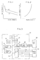
- a welding voltage V of a typical arc welding machine drops straight and drastically as a welding current I increases in a first welding current region where the welding current I takes a small value.
- the welding voltage V drops straight at a rate of change lower than the rate of change in the first welding current region as the welding current I increases.
- the greater the power supply output of the welding machine the higher the welding voltage V is (in Fig. 1, symbols U1 and U2 (> U1) designate values of the power supply output).
- the welding voltage V can be expressed as a function of the welding current I and the power supply output U, as is given by equation (1).
- V f(I, U). (1)
- the welding current I of the typical arc welding machine increases along a curve of second degree as an electrode feeding speed FW increases.
- the electrode feeding speed FW can be expressed as a function of the welding current I, as is given by equation (2).
- FW g(I).
- the welding current-welding voltage characteristic and welding current-electrode feeding speed characteristic of the arc welding machine exemplarily illustrated in Figs. 1 and 2 vary in dependence on welding conditions including the type of the electrode (physical properties of the electrode, such as electrode material, electrode diameter, etc.).
- the control process of Fig. 4 is periodically executed, and the target values of the wire feeding speed and the power supply output are updated or maintained so that the welding current and voltage errors are compensated.
- the welding machine 30 adjusts the wire feeding speed and the power supply output to the target values, so that the welding current and voltage are automatically controlled for the target values.
Landscapes
- Engineering & Computer Science (AREA)
- Physics & Mathematics (AREA)
- Plasma & Fusion (AREA)
- Mechanical Engineering (AREA)
- Arc Welding Control (AREA)
Claims (3)
- Für einen eine Elektrodentransporteinrichtung eines Lichtbogenschweißgeräts mit Energieversorgung involvierenden Vorgang bestimmtes Verfahren zur Steuerung eines Lichtbogenschweißstroms und einer Lichtbogenschweißspannung, mit den Schritten:a) Detektieren des Wertes (I) des Lichtbogenschweißstroms und des Wertes (V) der Lichtbogenschweißspannung,b) Berechnen eines Fehlers (εI) zwischen dem detektierten Wert (I) des Lichtbogenschweißstroms und einem Sollwert (IO) dieses Stroms und eines Fehlers (εV) zwischen dem detektierten Wert (V) der Lichtbogenschweißspannung und einem Sollwert (VO) dieser Spannung,c) Berechnen einer Korrekturgröße (ΔFW) der Elektrodentransportgeschwindigkeit des Lichtbogenschweißgeräts (30) in Abhängigkeit von einem berechneten Fehler,d) Berechnen einer Korrekturgröße (ΔU) eines Energieversorgungsausgangswertes des Lichtbogenschweißgeräts (30) in Abhängigkeit von den Fehlern (εI, εV) des Lichtbogenschweißstroms und der Lichtbogenschweißspannung, unde) Korrigieren der Elektrodentransportgeschwindigkeit und des Energieversorgungsausgangswertes in Abhängigkeit von deren Korrekturgrößen (ΔFW, ΔU),dadurch gekennzeichnet, daß
der Schritt a) eine Detektion des Lichtbogenschweißstroms und der Lichtbogenschweißspannung zu einer vorbestimmten Zahl Zeitpunkte (CO) sowie eine Berechnung eines Mittelwerts der jeweils detektierten Werte des Lichtbogenschweißstroms und eines Mittelwerts der jeweils detektierten Werte der Lichtbogenschweißspannung zur Verwendung als detektierter Wert (I, V) des Lichtbogenschweißstroms bzw. der Lichtbogenschweißspannung umfaßt,
der Schritt b) eine Berechnung beider Fehler (εI, εV) unter Verwendung der zwei Mittelwerte (I, V) umfaßt,
der Schritt c) eine Berechnung der Korrekturgröße (ΔFW) der Elektrodentransportgeschwindigkeit in Abhängigkeit vom berechneten Fehler (εI) des Lichtbogenschweißstroms umfaßt, und
beim Schritt d) die berechnete Korrekturgröße (ΔU) der elektrischen Ausgangsleistung der Energieversorgung des Schweißgeräts die berechnete Korrekturgröße ist. - Verfahren zur Steuerung des LichtbogenschweißstromS und der Lichtbogenschweißspannung nach Anspruch 1, mit dem Schritt einer Feststellung, ob der berechnete Fehler (εI) des Lichtbogenschweißstroms in einen zulässigen Bereich fällt oder nicht, wobei die Berechnung der Korrekturgröße (ΔFW) der Elektrodentransportgeschwindigkeit beim Schritt c) in Abhängigkeit von der Feststellung, daß dieser berechnete Fehler (εI) vom zulässigen Bereich abweicht, ausgeführt wird, und mit dem Schritt einer Feststellung, ob der berechnete Fehler (εV) der Lichtbogenschweißspannung in einen zulässigen Bereich fällt oder nicht, wobei die Berechnung der Korrekturgröße des Energieversorgungsausgangswertes beim Schritt d) in Abhängigkeit von der Feststellung, daß dieser berechnete Fehler (εV) vom zulässigen Bereich abweicht, ausgeführt wird.
- Verfahren zur Steuerung des Lichtbogenschweißstroms und der Lichtbogenschweißspannung nach Anspruch 1 oder 2, wobei der Schritt c) die Berechnung der Korrekturgröße (ΔFW) der Elektrodentransportgeschwindigkeit durch Einsetzen des detektierten Wertes (I) und des Fehlers (εI) des Lichtbogenschweißstroms in eine vorbestimmte, den Wert (I) des Lichtbogenschweißstroms und eine Änderungsgröße dieses Stroms als Variable enthaltende Berechnungsformel umfaßt, und wobei der Schritt d) die Berechnung der Korrekturgröße (ΔU) des Energieversorgungsausgangswertes durch Einsetzen der Fehler (εI, εV) des Lichtbogenschweißstroms und der Lichtbogenschweißspannung in eine vorbestimmte, eine Änderungsgröße des Lichtbogenschweißstroms (I) und der Lichtbogenschweißspannung (V) als Variable enthaltende Berechnungsformel umfaßt.
Applications Claiming Priority (3)
| Application Number | Priority Date | Filing Date | Title |
|---|---|---|---|
| JP1220206A JP2700823B2 (ja) | 1989-08-29 | 1989-08-29 | アーク溶接電流・電圧フィードバック制御方法 |
| JP220206/89 | 1989-08-29 | ||
| PCT/JP1990/000989 WO1991003351A1 (fr) | 1989-08-29 | 1990-08-02 | Procede de regulation du courant et de la tension de soudage a l'arc |
Publications (3)
| Publication Number | Publication Date |
|---|---|
| EP0451279A1 EP0451279A1 (de) | 1991-10-16 |
| EP0451279A4 EP0451279A4 (en) | 1992-09-09 |
| EP0451279B1 true EP0451279B1 (de) | 1994-10-19 |
Family
ID=16747551
Family Applications (1)
| Application Number | Title | Priority Date | Filing Date |
|---|---|---|---|
| EP90911706A Expired - Lifetime EP0451279B1 (de) | 1989-08-29 | 1990-08-02 | Steuerverfahren für strom und spannung bei bogenschweissen |
Country Status (5)
| Country | Link |
|---|---|
| US (1) | US5233158A (de) |
| EP (1) | EP0451279B1 (de) |
| JP (1) | JP2700823B2 (de) |
| DE (1) | DE69013492T2 (de) |
| WO (1) | WO1991003351A1 (de) |
Families Citing this family (39)
| Publication number | Priority date | Publication date | Assignee | Title |
|---|---|---|---|---|
| JP2503712B2 (ja) * | 1990-03-08 | 1996-06-05 | 三菱電機株式会社 | エレベ―タ―の速度制御装置 |
| WO1992000826A1 (fr) * | 1990-07-13 | 1992-01-23 | Sodick Co., Ltd. | Procede et appareil de generation d'impulsions |
| US5442726A (en) * | 1994-02-22 | 1995-08-15 | Hubbell Incorporated | Optical fiber storage system |
| JPH07303966A (ja) * | 1994-05-11 | 1995-11-21 | Fanuc Ltd | ロボット制御装置 |
| US5770834A (en) * | 1996-08-14 | 1998-06-23 | Abb Flexible Automation, Inc. | Robot control system and method for TIG welding |
| DE19702911C1 (de) * | 1997-01-28 | 1998-07-30 | Leipold & Co Gmbh | Elektronische Schweißenergiequelle |
| JP4780570B2 (ja) * | 1998-09-04 | 2011-09-28 | 独立行政法人物質・材料研究機構 | アーク溶接方法 |
| JP2000271888A (ja) * | 1999-03-25 | 2000-10-03 | Fanuc Ltd | ロボット制御装置 |
| US6642481B2 (en) * | 2001-05-11 | 2003-11-04 | Illinois Tool Works Inc. | Integrated welding control and power supply using phased control power technology |
| US6642482B2 (en) * | 2001-09-19 | 2003-11-04 | Illinois Tool Works Inc. | Welding-type system with robot calibration |
| JP3736411B2 (ja) * | 2001-09-28 | 2006-01-18 | 松下電器産業株式会社 | ア−ク溶接装置 |
| KR20030049325A (ko) * | 2001-12-14 | 2003-06-25 | 삼성전자주식회사 | 아크용접장치와 그 제어방법 |
| US7092660B2 (en) | 2003-05-26 | 2006-08-15 | Seiko Epson Corporation | Image forming apparatus |
| RU2238827C1 (ru) * | 2003-07-10 | 2004-10-27 | Томский политехнический университет | Способ управления размером капли расплавленного металла при сварке с импульсной подачей сварочной проволоки |
| US7091449B2 (en) * | 2003-09-02 | 2006-08-15 | Illinois Tool Works Inc. | Voltage regulated MIG welding using a constant current power source |
| EP1512481A3 (de) * | 2003-09-02 | 2011-09-28 | Illinois Tool Works Inc. | Spannungsgeregeltes GMA-Schweissen mit einer Konstantstromleistungsquelle und einem Drahtvorschubgerät mit variabler Verstärkung |
| CN1978114B (zh) * | 2005-11-30 | 2011-03-16 | 陈大可 | 弧焊电源的电弧功率控制方法及装置 |
| JP5101943B2 (ja) * | 2007-07-31 | 2012-12-19 | 株式会社ダイヘン | アーク溶接電源 |
| US9442481B2 (en) * | 2008-01-09 | 2016-09-13 | Illinois Tool Works Inc. | Automatic weld arc monitoring system |
| RU2429111C2 (ru) * | 2009-07-06 | 2011-09-20 | Государственное образовательное учреждение высшего профессионального образования "Томский политехнический университет" | Комбинированный способ импульсного управления процессом сварки плавящимся электродом |
| EP2580017B1 (de) * | 2010-06-14 | 2014-04-16 | Esab AB | Verfahren zur automatischen einstellung eines schweissparameters für mig/mag-schweissen und steuerung zur durchführung des verfahrens |
| JP5556734B2 (ja) * | 2011-04-20 | 2014-07-23 | 株式会社安川電機 | 溶接システムおよび溶接システム用ロボット制御装置 |
| CA2837385A1 (en) | 2011-05-26 | 2012-11-29 | Thermal Dynamics Corporation | Improved initiation of welding arc by restricting output |
| CN103747912B (zh) * | 2011-05-26 | 2016-08-17 | 维克托设备公司 | 产生焊接的系统及利用基于计算的焊接输出功率的电压和送丝速度的修正控制焊机的方法 |
| JP5907614B2 (ja) * | 2012-02-24 | 2016-04-26 | 株式会社ダイヘン | 消耗電極アーク溶接制御方法 |
| US9862050B2 (en) * | 2012-04-03 | 2018-01-09 | Lincoln Global, Inc. | Auto steering in a weld joint |
| CN102873433B (zh) * | 2012-07-03 | 2014-11-26 | 广东技术师范学院 | 一种双丝弧焊送丝速度预测设定方法 |
| CN102773588B (zh) * | 2012-08-04 | 2015-01-07 | 深圳市瑞凌实业股份有限公司 | 弧压跟踪脉冲埋弧焊控制方法、控制电路及焊机 |
| JP5950747B2 (ja) * | 2012-08-07 | 2016-07-13 | 株式会社ダイヘン | 消耗電極アーク溶接制御方法 |
| FR2994872B1 (fr) * | 2012-09-05 | 2014-09-26 | Air Liquide Welding France | Dispositif de soudage a l'arc avec selection automatique du regime de transfert de metal |
| US10035211B2 (en) | 2013-03-15 | 2018-07-31 | Lincoln Global, Inc. | Tandem hot-wire systems |
| US10086465B2 (en) | 2013-03-15 | 2018-10-02 | Lincoln Global, Inc. | Tandem hot-wire systems |
| US10464168B2 (en) | 2014-01-24 | 2019-11-05 | Lincoln Global, Inc. | Method and system for additive manufacturing using high energy source and hot-wire |
| JP6339651B1 (ja) * | 2016-12-02 | 2018-06-06 | ファナック株式会社 | アーク溶接ロボットシステム |
| US11027362B2 (en) | 2017-12-19 | 2021-06-08 | Lincoln Global, Inc. | Systems and methods providing location feedback for additive manufacturing |
| US11033978B2 (en) * | 2018-02-28 | 2021-06-15 | Esab Ab | Arc voltage sensing and control for a welding apparatus |
| US11311958B1 (en) * | 2019-05-13 | 2022-04-26 | Airgas, Inc. | Digital welding and cutting efficiency analysis, process evaluation and response feedback system for process optimization |
| JP7376377B2 (ja) * | 2020-01-29 | 2023-11-08 | 株式会社神戸製鋼所 | ガスシールドアーク溶接の出力制御方法、溶接システム、溶接電源及び溶接制御装置 |
| CN112775522B (zh) * | 2020-12-23 | 2022-09-23 | 唐山松下产业机器有限公司 | 高效tig的送丝方法与焊接设备 |
Family Cites Families (11)
| Publication number | Priority date | Publication date | Assignee | Title |
|---|---|---|---|---|
| US3538376A (en) * | 1967-03-03 | 1970-11-03 | Air Reduction | Arc current stabilization by control of electrode feed speed |
| JPS5232625B2 (de) * | 1973-03-29 | 1977-08-23 | ||
| JPS5357155A (en) * | 1976-11-04 | 1978-05-24 | Osaka Transformer Co Ltd | Transister direct current source for welding |
| JPS57112975A (en) * | 1980-12-29 | 1982-07-14 | Sansha Electric Mfg Co Ltd | Dc arc welding machine |
| JPS57199566A (en) * | 1981-06-02 | 1982-12-07 | Matsushita Electric Ind Co Ltd | Controlling method for arc welding |
| JPS5823569A (ja) * | 1981-07-31 | 1983-02-12 | Mitsubishi Electric Corp | 直流ア−ク溶接装置 |
| US4521672A (en) * | 1981-10-27 | 1985-06-04 | Miller Electric Manufacturing Company | Electronic welding apparatus |
| US4441009A (en) * | 1982-04-26 | 1984-04-03 | Larry Russell | Arc voltage control circuit for welding apparatus |
| DE3317028C2 (de) * | 1983-05-10 | 1985-12-05 | Utp Schweissmaterial Gmbh & Co, 7812 Bad Krozingen | Einrichtung zum Metallichtbogenschweißen |
| JPS61245971A (ja) * | 1985-04-22 | 1986-11-01 | Kawasaki Steel Corp | 自動ア−ク溶接機の制御方法 |
| US4851639A (en) * | 1988-09-29 | 1989-07-25 | Nkk Corporation | Apparatus for automatically welding cylindrical vessel |
-
1989
- 1989-08-29 JP JP1220206A patent/JP2700823B2/ja not_active Expired - Lifetime
-
1990
- 1990-08-02 EP EP90911706A patent/EP0451279B1/de not_active Expired - Lifetime
- 1990-08-02 US US07/674,331 patent/US5233158A/en not_active Expired - Fee Related
- 1990-08-02 WO PCT/JP1990/000989 patent/WO1991003351A1/ja not_active Ceased
- 1990-08-02 DE DE69013492T patent/DE69013492T2/de not_active Expired - Fee Related
Also Published As
| Publication number | Publication date |
|---|---|
| EP0451279A1 (de) | 1991-10-16 |
| DE69013492D1 (de) | 1994-11-24 |
| WO1991003351A1 (fr) | 1991-03-21 |
| US5233158A (en) | 1993-08-03 |
| EP0451279A4 (en) | 1992-09-09 |
| DE69013492T2 (de) | 1995-02-23 |
| JP2700823B2 (ja) | 1998-01-21 |
| JPH0386376A (ja) | 1991-04-11 |
Similar Documents
| Publication | Publication Date | Title |
|---|---|---|
| EP0451279B1 (de) | Steuerverfahren für strom und spannung bei bogenschweissen | |
| US4724302A (en) | Bead process control with profiler | |
| US10503130B2 (en) | Controller | |
| JP2011134169A (ja) | 制御パラメータ調整方法及び調整装置 | |
| EP0021856A1 (de) | Führungssystem für Schweisselektrode | |
| JP6517867B2 (ja) | 数値制御装置 | |
| US5440092A (en) | Welding controller and/or pinching force controller | |
| KR0164629B1 (ko) | 방전가공 제어방법 및 방전가공 제어장치 | |
| EP0378690A1 (de) | Anordnung zum nachweis der übermässigen lageabweichung in einem servosystem | |
| US5347105A (en) | Welding controller | |
| US5063281A (en) | Weaving welding method | |
| EP3354404B1 (de) | System mit einer drahterodiermaschine und einer numerischen steuerung | |
| JP3295920B2 (ja) | 張力制御方法 | |
| EP0192775A1 (de) | Steuersystem zum betreiben einer fliessbandanlage | |
| EP0562111B1 (de) | Abstandsteuerverfahren und -vorrichtung einer plasmaschneidmaschine | |
| EP0198090B1 (de) | Korrektursystem der spur einer selbsttätigen schweissvorrichtung | |
| JP2624099B2 (ja) | ワイヤ放電加工装置 | |
| JPH0985441A (ja) | アーク溶接の自動制御装置 | |
| JPH07178551A (ja) | 消耗電極式アーク溶接機のワイヤ送給速度制御装置 | |
| JPH08132243A (ja) | プラズマ切断装置におけるトーチ高さ制御装置 | |
| JPH0818138B2 (ja) | プラズマ加工機のスタンドオフ制御方法 | |
| JPH0630809B2 (ja) | 自動ア−ク溶接機の制御装置 | |
| JP2638401B2 (ja) | 消耗電極式アーク溶接機のワイヤ送給速度制御装置 | |
| JPH0330468B2 (de) | ||
| JPS60206579A (ja) | 溶接装置の溶接条件校正法 |
Legal Events
| Date | Code | Title | Description |
|---|---|---|---|
| PUAI | Public reference made under article 153(3) epc to a published international application that has entered the european phase |
Free format text: ORIGINAL CODE: 0009012 |
|
| 17P | Request for examination filed |
Effective date: 19910514 |
|
| AK | Designated contracting states |
Kind code of ref document: A1 Designated state(s): DE FR GB |
|
| A4 | Supplementary search report drawn up and despatched |
Effective date: 19920722 |
|
| AK | Designated contracting states |
Kind code of ref document: A4 Designated state(s): DE FR GB |
|
| 17Q | First examination report despatched |
Effective date: 19930107 |
|
| GRAA | (expected) grant |
Free format text: ORIGINAL CODE: 0009210 |
|
| AK | Designated contracting states |
Kind code of ref document: B1 Designated state(s): DE FR GB |
|
| PG25 | Lapsed in a contracting state [announced via postgrant information from national office to epo] |
Ref country code: FR Effective date: 19941019 |
|
| REF | Corresponds to: |
Ref document number: 69013492 Country of ref document: DE Date of ref document: 19941124 |
|
| EN | Fr: translation not filed | ||
| PG25 | Lapsed in a contracting state [announced via postgrant information from national office to epo] |
Ref country code: GB Effective date: 19950802 |
|
| PLBE | No opposition filed within time limit |
Free format text: ORIGINAL CODE: 0009261 |
|
| STAA | Information on the status of an ep patent application or granted ep patent |
Free format text: STATUS: NO OPPOSITION FILED WITHIN TIME LIMIT |
|
| 26N | No opposition filed | ||
| GBPC | Gb: european patent ceased through non-payment of renewal fee |
Effective date: 19950802 |
|
| PGFP | Annual fee paid to national office [announced via postgrant information from national office to epo] |
Ref country code: DE Payment date: 20000729 Year of fee payment: 11 |
|
| PG25 | Lapsed in a contracting state [announced via postgrant information from national office to epo] |
Ref country code: DE Free format text: LAPSE BECAUSE OF NON-PAYMENT OF DUE FEES Effective date: 20020501 |