EP0451469A1 - Forme de bombage et de soutien des feuilles de verre - Google Patents
Forme de bombage et de soutien des feuilles de verre Download PDFInfo
- Publication number
- EP0451469A1 EP0451469A1 EP91102653A EP91102653A EP0451469A1 EP 0451469 A1 EP0451469 A1 EP 0451469A1 EP 91102653 A EP91102653 A EP 91102653A EP 91102653 A EP91102653 A EP 91102653A EP 0451469 A1 EP0451469 A1 EP 0451469A1
- Authority
- EP
- European Patent Office
- Prior art keywords
- mould
- bending
- orifices
- channels
- set forth
- Prior art date
- Legal status (The legal status is an assumption and is not a legal conclusion. Google has not performed a legal analysis and makes no representation as to the accuracy of the status listed.)
- Granted
Links
- 238000005452 bending Methods 0.000 title claims abstract description 43
- 239000011521 glass Substances 0.000 title claims abstract description 25
- 238000009826 distribution Methods 0.000 claims abstract description 49
- 238000007493 shaping process Methods 0.000 claims abstract description 45
- 238000005266 casting Methods 0.000 claims abstract description 23
- 239000000463 material Substances 0.000 claims abstract description 21
- 238000004519 manufacturing process Methods 0.000 claims abstract description 16
- 239000000919 ceramic Substances 0.000 claims abstract description 12
- 238000004891 communication Methods 0.000 claims abstract description 4
- 229910010293 ceramic material Inorganic materials 0.000 claims abstract description 3
- 238000000034 method Methods 0.000 claims description 14
- 238000010438 heat treatment Methods 0.000 claims description 7
- 230000001788 irregular Effects 0.000 claims description 3
- 239000003546 flue gas Substances 0.000 claims description 2
- 239000002904 solvent Substances 0.000 claims description 2
- 235000002918 Fraxinus excelsior Nutrition 0.000 claims 1
- 239000002956 ash Substances 0.000 claims 1
- 238000007599 discharging Methods 0.000 claims 1
- 238000004090 dissolution Methods 0.000 claims 1
- 238000011010 flushing procedure Methods 0.000 claims 1
- 239000011343 solid material Substances 0.000 claims 1
- 238000005422 blasting Methods 0.000 description 19
- 230000005465 channeling Effects 0.000 description 11
- 239000007789 gas Substances 0.000 description 8
- 238000013461 design Methods 0.000 description 7
- 238000005553 drilling Methods 0.000 description 4
- 230000000694 effects Effects 0.000 description 4
- 238000013459 approach Methods 0.000 description 3
- 238000012546 transfer Methods 0.000 description 3
- 238000007664 blowing Methods 0.000 description 2
- 229910052751 metal Inorganic materials 0.000 description 2
- 239000002184 metal Substances 0.000 description 2
- 150000002739 metals Chemical class 0.000 description 2
- 239000004033 plastic Substances 0.000 description 2
- 229920003023 plastic Polymers 0.000 description 2
- 238000012545 processing Methods 0.000 description 2
- 239000000853 adhesive Substances 0.000 description 1
- 230000000712 assembly Effects 0.000 description 1
- 238000000429 assembly Methods 0.000 description 1
- 230000000903 blocking effect Effects 0.000 description 1
- 230000001413 cellular effect Effects 0.000 description 1
- 238000002485 combustion reaction Methods 0.000 description 1
- 238000010276 construction Methods 0.000 description 1
- 238000001816 cooling Methods 0.000 description 1
- 238000005336 cracking Methods 0.000 description 1
- 229920001971 elastomer Polymers 0.000 description 1
- 238000005516 engineering process Methods 0.000 description 1
- 238000005304 joining Methods 0.000 description 1
- 230000004807 localization Effects 0.000 description 1
- 230000002787 reinforcement Effects 0.000 description 1
- 230000000630 rising effect Effects 0.000 description 1
- 239000005060 rubber Substances 0.000 description 1
- 239000004576 sand Substances 0.000 description 1
- 238000007789 sealing Methods 0.000 description 1
- 239000007787 solid Substances 0.000 description 1
Images


Classifications
-
- C—CHEMISTRY; METALLURGY
- C03—GLASS; MINERAL OR SLAG WOOL
- C03B—MANUFACTURE, SHAPING, OR SUPPLEMENTARY PROCESSES
- C03B23/00—Re-forming shaped glass
- C03B23/02—Re-forming glass sheets
- C03B23/023—Re-forming glass sheets by bending
- C03B23/03—Re-forming glass sheets by bending by press-bending between shaping moulds
- C03B23/0307—Press-bending involving applying local or additional heating, cooling or insulating means
-
- C—CHEMISTRY; METALLURGY
- C03—GLASS; MINERAL OR SLAG WOOL
- C03B—MANUFACTURE, SHAPING, OR SUPPLEMENTARY PROCESSES
- C03B23/00—Re-forming shaped glass
- C03B23/02—Re-forming glass sheets
- C03B23/023—Re-forming glass sheets by bending
- C03B23/035—Re-forming glass sheets by bending using a gas cushion or by changing gas pressure, e.g. by applying vacuum or blowing for supporting the glass while bending
-
- C—CHEMISTRY; METALLURGY
- C03—GLASS; MINERAL OR SLAG WOOL
- C03B—MANUFACTURE, SHAPING, OR SUPPLEMENTARY PROCESSES
- C03B23/00—Re-forming shaped glass
- C03B23/02—Re-forming glass sheets
- C03B23/023—Re-forming glass sheets by bending
- C03B23/035—Re-forming glass sheets by bending using a gas cushion or by changing gas pressure, e.g. by applying vacuum or blowing for supporting the glass while bending
- C03B23/0352—Re-forming glass sheets by bending using a gas cushion or by changing gas pressure, e.g. by applying vacuum or blowing for supporting the glass while bending by suction or blowing out for providing the deformation force to bend the glass sheet
-
- C—CHEMISTRY; METALLURGY
- C03—GLASS; MINERAL OR SLAG WOOL
- C03B—MANUFACTURE, SHAPING, OR SUPPLEMENTARY PROCESSES
- C03B35/00—Transporting of glass products during their manufacture, e.g. hot glass lenses, prisms
- C03B35/14—Transporting hot glass sheets or ribbons, e.g. by heat-resistant conveyor belts or bands
- C03B35/20—Transporting hot glass sheets or ribbons, e.g. by heat-resistant conveyor belts or bands by gripping tongs or supporting frames
- C03B35/202—Transporting hot glass sheets or ribbons, e.g. by heat-resistant conveyor belts or bands by gripping tongs or supporting frames by supporting frames
-
- C—CHEMISTRY; METALLURGY
- C03—GLASS; MINERAL OR SLAG WOOL
- C03B—MANUFACTURE, SHAPING, OR SUPPLEMENTARY PROCESSES
- C03B35/00—Transporting of glass products during their manufacture, e.g. hot glass lenses, prisms
- C03B35/14—Transporting hot glass sheets or ribbons, e.g. by heat-resistant conveyor belts or bands
- C03B35/22—Transporting hot glass sheets or ribbons, e.g. by heat-resistant conveyor belts or bands on a fluid support bed, e.g. on molten metal
- C03B35/24—Transporting hot glass sheets or ribbons, e.g. by heat-resistant conveyor belts or bands on a fluid support bed, e.g. on molten metal on a gas support bed
Definitions
- the present invention relates to a glass sheet bending or supporting mould which is made primarily by casting of a ceramic material and which includes a curving or flat shaping surface, a number of orifices in the shaping surface and channels extending through the mould material and in communication with the orifices.
- the invention relates also to a method for manufacturing a glass sheet bending or supporting mould, which method involves casting of a ceramic-based material into a mould-casting mould which defines the shaping surface of a bending or supporting mould to be cast.
- hot-gas jets In the further processing of glass there is plenty of use for hot-gas jets.
- the jets are capable of providing a good heat transfer coefficient, a heat transfer nearly independent of emissivity, effective heat localization, a gas support and non-contacting press bending.
- the applications are abundant.
- production of appropriate hot-gas jets involves problems as well.
- it is difficult to fabricate an extensive, orificed shaping surface of a desired configuration which retains its shape accurately at a rising temperature. In practice, this means that a mould or the like must be made of a ceramic-based material, whereby the thermal expansion remains low if necessary.
- Another possibility is to use a ceramic to design a mould provided with chambers and fitted e.g. with a pipe joint. The holes are drilled through a thin jacket.
- a problem is how to design a chamber and the presence of ceramic mould reinforcements which prevent the drilling of holes in every section.
- US Patent specification 4 767 437 discloses a double channeled overhead vacuum pickup provided with a channeling for both blasting air and suction air.
- the suction air channel system is designed in the above-described fashion by drilling holes through the entire plate-like pickup and by placing the top surface of the pickup in a vacuum chamber.
- the fitting and tightening between mould and vacuum chamber cause problems.
- the blasting channel system is designed by using large channels inside the pickup, the other ends of said channels being connected with a pressure chamber located along one side of the pickup. The blasting orifices are drilled through the mould material from the pickup surface to the internal channels.
- this solution involves a problem of joining and sealing the ends of the channels with a common inlet air pipe.
- An object of the invention is to provide an improved mould, wherein the channeling is designed inside the mould in a manner that there is no need for out-of-mould vacuum or positive pressure chambers as part of the channel system.
- a particular object of the invention is to provide a mould, wherein double channeling is also designed in a simple manner entirely inside the mould.
- Another object of the invention is to provide a novel mould fabrication method for carrying out a desired channeling, including double channeling, readily by means of intra-mould channels.
- a particular object of the invention is to provide a method for readily designing an intra-mould channel system and also a double channel system in a desired configuration also in connection of curved surface moulds.
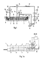
- fig. 1 shows schematically a mould according to one embodiment of the invention and its application as a non-engaging press bending mould.
- Fig. 1A is a side view of a furnace unit wherein the present invention can be applied.
- Fig. 2 shows a vertical section of a portion of a mould of the invention in an operating situation with the mould serving as a press bending mould.
- Fig. 3 is a perspective view of a ladder-like or lattice-like temporary filling used in the mould fabrication method for making a distribution channel system or manifold.
- Fig. 4 is a view similar to fig. 3 showing some of the temporary filling within the area of a curved shaping surface.
- Fig. 5 is a vertical section of some of the temporary filling to form a double channel system, said filling being placed in a mould-manufacturing mould 32.
- Fig. 6 is a plan view of one of the temporary fillings shown in fig. 5.
- the embodiment of fig. 1 shows a press bending mould 6 provided with a blasting manifold 16 and a suction manifold 17 and with a less curving or flat partial shaping surface 7 and a more curving partial shaping surface 8 which, within the mould corner areas, can also be a part of spherical surface.
- the press bending mould 6 is placed in a bending section 4 for complicated bending shapes, into which a hot glass sheet supported by an outline or ring-type mould 5 is carried from the final heating section 3. Heating of a glass sheet is effected step by step in successive heating sections 2. A bent glass sheet is gradually cooled in successive cooling sections 3', 2'.
- a windshield bending furnace generally indicated by reference numeral 1 is described in more detail in US Patent publication 4 497 645.
- Orifices 10 are connected to blasting-air distribution manifold 16 and orifices 11 are connected to suction-air collecting manifold 17. In curving shaping surface sections 8 and in the immediate vicinity thereof, said blasting air orifices 10 are connected to separate distribution manifold sections 18. Distribution manifolds 16 and 18 are connected by way of blasting air pipes 12 and 14 to an adjustable three-way valve 24 for adjusting the relative amount of blasting air between pipes 12 and 14. Valve 24 is connected by way of a blasting air pipe 27 to the pressure side of a fan 22. The suction side of fan 22 is connected to an adjustable three-way valve 20 for adjusting the relative proportions of the amounts of air coming from a pipe 19 and a pipe 13.
- Pipe 13 is connected to said suction-air collecting manifold 17 of the mould and pipe 19 is connected to the interior of the hottest section 3 of furnace 1.
- valve 20 is capable of controlling the effect of suction prevailing on the shaping surface in relation to the effect of blowing.
- heaters 21 and 23 On either side of fan 22 there are heaters 21 and 23 which are controlled by thermostats 26.
- the blasting pipe branch 14 can further be fitted with a controllable heater 25 for blowing hotter air to the most curving shaping surface sections 8 and to the immediate vicinity thereof than to the less curving section 7.
- a greater blasting air thermal effect is required in the areas subjected to the greates deformation (deflection and/or elongation) of a glass sheet.
- this objective can be achieved in a variety of ways also when using a single integrated blasting air distribution manifold 16.
- One useful approach is to apply a greater amount of blasting air wherever more heat is required. Therefore, the pitch of orifices can be made irregular. In other words, the orifices are in a more dense pattern in those surface regions which require more heating.
- Another possibility is to include orifices of varying sizes within different areas of a shaping surface.
- Yet another possibility is to locate resistance heating elements (see resistance 28 in fig. 4) in different parts of distribution manifold 16 or 18. Power is supplied to the resistance heating elements from a power source 30 by way of wires 29.
- a novel and unique feature of the invention is the design of blasting air distribution manifold 16, 18 as well as that of collection manifold 17.
- the blasting air distribution channels 16 are connected to each other by means of transverse connecting channels 161.
- the suction air collection channels 17 are also connected to each other by means of transverse connecting channels 171.
- the distribution channels 16 and connecting channels 161 build a ladder-like or lattice-like distribution manifold.
- the collection channels 17 and connecting channels 171 build a ladder-like or lattice-like collection manifold. Both ladder-like or lattice-like manifolds extend themselves within the mould at least substantially in the same direction as the shaping surface.
- the individual channel members of manifolds 16, 161 or 17, 171 can extend in a zigzag fashion and also diverge substantially from the direction of a shaping surface.
- the individual channel members are also, at least for the most part, parallel to the shaping surface.
- Between distribution manifold 16, 161 and orifices 10 extend tapering nozzle channels 162.
- Between collection manifold 17, 171 and orifices 11 extend tapering nozzle channels 172.
- such a double manifold is required for effecting a non-engaging press bending operation to a glass sheet 9.
- a heat glass sheet is supported on an outline mould 5 provided with a shaping surface 15 to match a desired final bending shape.
- the upper press bending mould 6 is also provided with a shaping surface 7, 8 to match a final desired bending shape.
- Each individual distribution manifold 16, 161 or manifold section (18 in fig. 1) has at least one pressure pipe 12, 14 connected thereto. Accordingly, the collection manifold 17 has at least a single suction pipe 13 connected thereto.
- the orifices 10 and 11 can have a diameter of 2 - 10 mm, e.g. 5 mm.
- the blast and suction orifices can be made either stepwise in adjacent rows or alternately in the same orifice rows.
- the distance or spacing between blast and suction orifices can be 20 - 50 mm, e.g. 30 mm.
- a ladder or lattice assembly corresponding to a desired distribution manifold is prefabricated of such a material which can be removed during or after the baking stage of a ceramic mould 6.
- An essential feature is that the material employed does not experience too much heat expansion during the baking stage and thus cause splitting and cracking of the ceramic mould.
- the applicable materials include e.g. certain types of plastics, certain types of rubbers, some cellular plastics, organic-adhesive bound casting cores (turn to sand after baking), pipes made of low softening point metals etc.
- a pressure pipe 12 is connected through the intermediary of a branch pipe or a temporary filling member 121 to filling members 122 extending parallel to the shaping surface and forming distribution channels of the first step.
- filling members 122 are connected through the intermediary of a branch piece to filling members 123, which are parallel to the shaping surface and form a distribution manifold of the second step.
- Filling members 123 are in turn connected to each other by means of transverse filling members 124 which form connecting pipes 161 between distribution channels 16.
- Filling members 125 form connecting channels between the distribution manifold and orifices 10.
- the filling members can be solid or tubular depending on a material employed.
- a filling member corresponding to collection manifold connected with suction pipe 13 and to nozzle manifold 172 can be manufactured in exactly the same way to be a single- or multi-step configuration.
- the filling members intended for building different manifolds must naturally be designed and dimensioned as well as attached inside a manufacturing mould in a manner to position them in a suitably overlapping, non-engaging relationship relative to each other.
- the filling members must be tied and braced in a casting mould so that the latter is capable of withstanding the stress exerted by a casting operation.
- mould 6 is removed from the casting mould and the manifolds are created inside the mould by removing the filling material by using one or more of the following methods: Mould 6 is heated or baked in a manner that the filling material escapes as flue gases nad/ or is incinerated; channels are flushed with a solvent which dissolves and flushes away the filling material or combustion residues; mould 6 is heated to such a high temperature that the filling material converts or releases into a flowing or running state.
- the distribution manifold 16, 161 and 17, 171 are parallel to the shaping surface in a manner that the manifold is at every point substantially an equal distance away from the shaping surface.
- the channels can also meander to vary the distance thereof from the shaping surface. Even in this case, however, the general direction of a ladder-like or lattice-like channel assembly follows the direction of a shaping surface.
- a ladder-like or lattice-like assembly means that parallel channels 16 or 17 are connected to each other at certain spacings by means of transverse channels 161 or 171.
- the connecting transverse channel 161 or 171 can be smaller than the actual channel but, preferably, the channeling is designed in a manner that both the actual manifold and the connecting manifold are of the same size and the spacing between channels is equal to provide a lattice-like manifold.
- Figs. 5 and 6 illustrate a temporary filling to be placed in a casting mould for building a lattice-like manifold.
- Filling members 173 and 174 and respectively 163 and 164 build a regular square lattice whose crossing points are provided with filling members 175 and respectively 165 in the shape of a tapered rod or stub for building nozzle channels 172 and respectively 162.
- a casting mould 32 is provided with at least two separate channel filling assemblies in overlying planes in order to build similarly separate distribution and collection manifolds.
- the tapered rods or stubs 175 of the upper plane or level found their way to apertures in the channel filling of the lower level, the manifolds thus formed remaining separate from each other.
- the individual channel fillings can also be made of prefabricated sub-elements which are joined together to provide a single integral channel filling.
- prefabricated standard elements it is possible to build distribution manifolds of varying configurations.
- the ladder-like or lattice-like structure of a distribution or collection manifold offers the further benefit that, in case of a possible blocking or a manifold breakup during a mould-building operation, a back-up manifold will be automatically provided.
- the ladder-like or lattice-like structure further achieves the bracing of a temporary channel filling for the duration of mould manufacture. If the manifold is only built by suing individual pipes, there is a hazard of damaging the manifold e.g. during transport or manufacturing.
- the mould is particularly suitable for the further processing of painted or coated glasses by virtue of a gas film produced by means of the mould.
Landscapes
- Chemical & Material Sciences (AREA)
- Engineering & Computer Science (AREA)
- Materials Engineering (AREA)
- Organic Chemistry (AREA)
- Re-Forming, After-Treatment, Cutting And Transporting Of Glass Products (AREA)
- Moulds For Moulding Plastics Or The Like (AREA)
Applications Claiming Priority (2)
| Application Number | Priority Date | Filing Date | Title |
|---|---|---|---|
| FI901602 | 1990-03-30 | ||
| FI901602A FI84806C (fi) | 1990-03-30 | 1990-03-30 | Boejnings- eller stoedform foer glasskivor. |
Publications (2)
| Publication Number | Publication Date |
|---|---|
| EP0451469A1 true EP0451469A1 (fr) | 1991-10-16 |
| EP0451469B1 EP0451469B1 (fr) | 1995-05-17 |
Family
ID=8530171
Family Applications (1)
| Application Number | Title | Priority Date | Filing Date |
|---|---|---|---|
| EP91102653A Expired - Lifetime EP0451469B1 (fr) | 1990-03-30 | 1991-02-22 | Forme de bombage et de soutien des feuilles de verre |
Country Status (5)
| Country | Link |
|---|---|
| US (1) | US5079931A (fr) |
| EP (1) | EP0451469B1 (fr) |
| JP (1) | JPH04224124A (fr) |
| DE (1) | DE69109731T2 (fr) |
| FI (1) | FI84806C (fr) |
Cited By (3)
| Publication number | Priority date | Publication date | Assignee | Title |
|---|---|---|---|---|
| US5735922A (en) * | 1994-04-15 | 1998-04-07 | Pilkington Glass Limited | Method of bending and tempering glass sheets |
| US5755845A (en) * | 1994-04-15 | 1998-05-26 | Pilkington Glass Limited | Method and apparatus for bending and tempering glass sheets |
| FR2960232A1 (fr) * | 2010-05-19 | 2011-11-25 | Saint Gobain | Forme de bombage alveolaire |
Families Citing this family (17)
| Publication number | Priority date | Publication date | Assignee | Title |
|---|---|---|---|---|
| FI87920C (fi) * | 1991-04-26 | 1993-03-10 | Tamglass Eng Oy | Anordning foer boejning av en av kantform understoedd glasskiva |
| FI91061C (fi) * | 1992-05-27 | 1994-05-10 | Tamglass Eng Oy | Puristustaivutusmenetelmä ja -laite lasilevyjen taivuttamiseksi |
| FI91521C (fi) * | 1992-10-15 | 1996-09-11 | Tamglass Eng Oy | Menetelmä lasilevyjen taivuttamiseksi |
| US5308135A (en) * | 1993-05-13 | 1994-05-03 | Chrysler Corporation | Sacrificial stationary support for mounting safety glass in automotive vehicles and window installation method |
| US5746799A (en) * | 1994-06-20 | 1998-05-05 | Gas Research Institute | Process for heating glass sheets within a forced convection heating apparatus by mixing and distributing spent working fluid and combustion gases |
| US5669954A (en) * | 1994-06-20 | 1997-09-23 | Gas Research Institute | Forced convection heating apparatus and process for heating glass sheets therewithin |
| US5672191A (en) * | 1994-06-20 | 1997-09-30 | Gas Research Institute | Forced convection heating apparatus and process for heating glass sheets therewithin |
| US5669952A (en) * | 1994-10-14 | 1997-09-23 | Ppg Industries, Inc. | Pressure forming of glass sheets |
| US6045358A (en) * | 1996-01-19 | 2000-04-04 | Glasstech, Inc. | Forced convection heating apparatus and process for heating glass sheets therewithin |
| US5938810A (en) | 1996-10-23 | 1999-08-17 | Donnelly Corporation | Apparatus for tempering and bending glass |
| US5857358A (en) * | 1996-10-23 | 1999-01-12 | Donnelly Corporation | Method and apparatus for bending glass |
| US5951733A (en) * | 1998-08-04 | 1999-09-14 | Glasstech, Inc. | Mold apparatus and method for vacuum forming glass sheets |
| DE10149400B4 (de) * | 2001-10-06 | 2004-05-13 | Schott Glas | Verfahren und Vorrichtung zum kontaktlosen Formgeben von schmelzflüssigen Glasposten mittels Gaslevitation |
| DE10314408A1 (de) * | 2003-03-28 | 2004-10-07 | Pilkington Automotive Deutschland Gmbh | Vorrichtung zum Erzeugen eines Gaskissens |
| US9505654B2 (en) | 2013-06-06 | 2016-11-29 | Gyrotron Technology, Inc. | Method for the chemical strengthening of glass |
| WO2017029252A1 (fr) * | 2015-08-18 | 2017-02-23 | Saint-Gobain Glass France | Dispositif et procédé de cintrage de verre au moyen d'un ventilateur |
| TWI660920B (zh) * | 2018-06-25 | 2019-06-01 | 海納光電股份有限公司 | 非接觸成型裝置及方法 |
Citations (4)
| Publication number | Priority date | Publication date | Assignee | Title |
|---|---|---|---|---|
| US3634059A (en) * | 1969-08-20 | 1972-01-11 | Libbey Owens Ford Co | Glass sheet press bending mold |
| EP0131502A1 (fr) * | 1983-07-11 | 1985-01-16 | Societe Europeenne Des Produits Refractaires | Echangeurs de chaleur moulés en matière réfractaire |
| US4767437A (en) * | 1987-03-25 | 1988-08-30 | Ppg Industries, Inc. | Horizontal press bending using a splitting vacuum/pressure pickup |
| EP0388249A2 (fr) * | 1989-03-16 | 1990-09-19 | Saint-Gobain Vitrage International | Dispositif servant au transport et/ou à la mise en forme de feuilles de verre chauffées à leur température de ramollissement |
Family Cites Families (5)
| Publication number | Priority date | Publication date | Assignee | Title |
|---|---|---|---|---|
| GB1190371A (en) * | 1966-04-25 | 1970-05-06 | Pilkington Brothers Ltd | Improvements in or relating to the Bending of Glass Sheets |
| US3468645A (en) * | 1966-05-09 | 1969-09-23 | Permaglass | Method and apparatus for shaping glass sheets supported on a gas support bed |
| CH569999B5 (fr) * | 1971-12-09 | 1975-11-28 | Agency Ind Science Techn | |
| US4802903A (en) * | 1986-09-25 | 1989-02-07 | Saint-Gobain Vitrage | Method and apparatus for curving a glass sheet |
| FI76314C (fi) * | 1986-10-29 | 1988-10-10 | Kyro Oy | Stroemningshinder i kylavdelningen till en glashaerdningsanlaeggning. |
-
1990
- 1990-03-30 FI FI901602A patent/FI84806C/fi active IP Right Grant
- 1990-08-24 US US07/571,971 patent/US5079931A/en not_active Expired - Lifetime
-
1991
- 1991-02-22 DE DE69109731T patent/DE69109731T2/de not_active Expired - Fee Related
- 1991-02-22 EP EP91102653A patent/EP0451469B1/fr not_active Expired - Lifetime
- 1991-03-29 JP JP3091201A patent/JPH04224124A/ja active Pending
Patent Citations (4)
| Publication number | Priority date | Publication date | Assignee | Title |
|---|---|---|---|---|
| US3634059A (en) * | 1969-08-20 | 1972-01-11 | Libbey Owens Ford Co | Glass sheet press bending mold |
| EP0131502A1 (fr) * | 1983-07-11 | 1985-01-16 | Societe Europeenne Des Produits Refractaires | Echangeurs de chaleur moulés en matière réfractaire |
| US4767437A (en) * | 1987-03-25 | 1988-08-30 | Ppg Industries, Inc. | Horizontal press bending using a splitting vacuum/pressure pickup |
| EP0388249A2 (fr) * | 1989-03-16 | 1990-09-19 | Saint-Gobain Vitrage International | Dispositif servant au transport et/ou à la mise en forme de feuilles de verre chauffées à leur température de ramollissement |
Cited By (4)
| Publication number | Priority date | Publication date | Assignee | Title |
|---|---|---|---|---|
| US5735922A (en) * | 1994-04-15 | 1998-04-07 | Pilkington Glass Limited | Method of bending and tempering glass sheets |
| US5755845A (en) * | 1994-04-15 | 1998-05-26 | Pilkington Glass Limited | Method and apparatus for bending and tempering glass sheets |
| FR2960232A1 (fr) * | 2010-05-19 | 2011-11-25 | Saint Gobain | Forme de bombage alveolaire |
| US9096456B2 (en) | 2010-05-19 | 2015-08-04 | Saint-Gobain Glass France | Cellular bending mold |
Also Published As
| Publication number | Publication date |
|---|---|
| US5079931A (en) | 1992-01-14 |
| FI901602A7 (fi) | 1991-10-01 |
| FI84806B (fi) | 1991-10-15 |
| FI84806C (fi) | 1992-01-27 |
| DE69109731T2 (de) | 1995-10-05 |
| FI901602A0 (fi) | 1990-03-30 |
| EP0451469B1 (fr) | 1995-05-17 |
| JPH04224124A (ja) | 1992-08-13 |
| DE69109731D1 (de) | 1995-06-22 |
Similar Documents
| Publication | Publication Date | Title |
|---|---|---|
| EP0451469B1 (fr) | Forme de bombage et de soutien des feuilles de verre | |
| EP0448959B1 (fr) | Méthode et assemblage de moules pour bomber des feuilles de verre avec des formes complexes | |
| JP3618964B2 (ja) | タービンエンジンの中空羽根を製造する方法及び該方法の実施に使用する多重作用プレス炉 | |
| EP0121258B1 (fr) | Façonnage de formes complexes avec des feuilles de verre | |
| AU741677B2 (en) | Semi convective forced air system and method for tempering low E coated glass | |
| CN108136464A (zh) | 待控温的非无尽表面的均匀非接触温度控制方法及其装置 | |
| US5259859A (en) | Lightweight vacuum shuttle | |
| IT8223884A1 (it) | Stampo a vuoto deformabile per la sagomatura di lastre di vetro | |
| JPH04501555A (ja) | ガラス板搬送曲げ加工装置 | |
| FI72958C (fi) | Foerfarande och anordning foer termisk seghaerdning av glas. | |
| CN100593021C (zh) | 用于回火玻璃板的对流加热炉 | |
| JP4400158B2 (ja) | 板状体の加熱方法 | |
| CN100372790C (zh) | 用于弯曲玻璃板的设备 | |
| CN221822274U (zh) | 一种箱式回火炉 | |
| CN107448960A (zh) | 一种便于更换电热丝的voc废气高效净化炉 | |
| EP0448960B1 (fr) | Méthode et assemblage de moules pour bomber des formes difficiles en verre plat, comme une feuille de verre en forme de S | |
| JP5430556B2 (ja) | 曲面壁に支持リングを構築する方法 | |
| US5185022A (en) | Mould assembly for bending difficult bending shapes in a glass sheet | |
| CN217110527U (zh) | 一种窑炉尾部余热再利用装置 | |
| EP4509473B1 (fr) | Four de trempe et procédé d'assemblage de four de trempe | |
| CN221629783U (zh) | 一种应用于干燥炉的防熄火燃烧棒 | |
| KR100380749B1 (ko) | 열풍로의 열풍통풍성이 우수한 연와 | |
| JPS6051956B2 (ja) | 長尺中空構造物の溶接予熱方法 | |
| US4667396A (en) | Method of construction of a heat treatment furnace | |
| JPS629318Y2 (fr) |
Legal Events
| Date | Code | Title | Description |
|---|---|---|---|
| PUAI | Public reference made under article 153(3) epc to a published international application that has entered the european phase |
Free format text: ORIGINAL CODE: 0009012 |
|
| AK | Designated contracting states |
Kind code of ref document: A1 Designated state(s): CH DE FR GB IT LI |
|
| 17P | Request for examination filed |
Effective date: 19920224 |
|
| RAP1 | Party data changed (applicant data changed or rights of an application transferred) |
Owner name: TAMGLASS ENGINEERING OY |
|
| 17Q | First examination report despatched |
Effective date: 19930929 |
|
| GRAA | (expected) grant |
Free format text: ORIGINAL CODE: 0009210 |
|
| AK | Designated contracting states |
Kind code of ref document: B1 Designated state(s): CH DE FR GB IT LI |
|
| ITF | It: translation for a ep patent filed | ||
| REF | Corresponds to: |
Ref document number: 69109731 Country of ref document: DE Date of ref document: 19950622 |
|
| ET | Fr: translation filed | ||
| PLBE | No opposition filed within time limit |
Free format text: ORIGINAL CODE: 0009261 |
|
| STAA | Information on the status of an ep patent application or granted ep patent |
Free format text: STATUS: NO OPPOSITION FILED WITHIN TIME LIMIT |
|
| 26N | No opposition filed | ||
| PGFP | Annual fee paid to national office [announced via postgrant information from national office to epo] |
Ref country code: CH Payment date: 19970129 Year of fee payment: 7 |
|
| PG25 | Lapsed in a contracting state [announced via postgrant information from national office to epo] |
Ref country code: LI Free format text: LAPSE BECAUSE OF NON-PAYMENT OF DUE FEES Effective date: 19980228 Ref country code: CH Free format text: LAPSE BECAUSE OF NON-PAYMENT OF DUE FEES Effective date: 19980228 |
|
| REG | Reference to a national code |
Ref country code: CH Ref legal event code: PL |
|
| PGFP | Annual fee paid to national office [announced via postgrant information from national office to epo] |
Ref country code: FR Payment date: 19990208 Year of fee payment: 9 |
|
| PGFP | Annual fee paid to national office [announced via postgrant information from national office to epo] |
Ref country code: GB Payment date: 19990216 Year of fee payment: 9 |
|
| PGFP | Annual fee paid to national office [announced via postgrant information from national office to epo] |
Ref country code: DE Payment date: 19990226 Year of fee payment: 9 |
|
| PG25 | Lapsed in a contracting state [announced via postgrant information from national office to epo] |
Ref country code: GB Free format text: LAPSE BECAUSE OF NON-PAYMENT OF DUE FEES Effective date: 20000222 |
|
| GBPC | Gb: european patent ceased through non-payment of renewal fee |
Effective date: 20000222 |
|
| PG25 | Lapsed in a contracting state [announced via postgrant information from national office to epo] |
Ref country code: FR Free format text: LAPSE BECAUSE OF NON-PAYMENT OF DUE FEES Effective date: 20001031 |
|
| PG25 | Lapsed in a contracting state [announced via postgrant information from national office to epo] |
Ref country code: DE Free format text: LAPSE BECAUSE OF NON-PAYMENT OF DUE FEES Effective date: 20001201 |
|
| REG | Reference to a national code |
Ref country code: FR Ref legal event code: ST |
|
| PG25 | Lapsed in a contracting state [announced via postgrant information from national office to epo] |
Ref country code: IT Free format text: LAPSE BECAUSE OF NON-PAYMENT OF DUE FEES;WARNING: LAPSES OF ITALIAN PATENTS WITH EFFECTIVE DATE BEFORE 2007 MAY HAVE OCCURRED AT ANY TIME BEFORE 2007. THE CORRECT EFFECTIVE DATE MAY BE DIFFERENT FROM THE ONE RECORDED. Effective date: 20050222 |