EP0451494B1 - Calandre pour la fabrication de plaques d'étanchéité - Google Patents
Calandre pour la fabrication de plaques d'étanchéité Download PDFInfo
- Publication number
- EP0451494B1 EP0451494B1 EP91103201A EP91103201A EP0451494B1 EP 0451494 B1 EP0451494 B1 EP 0451494B1 EP 91103201 A EP91103201 A EP 91103201A EP 91103201 A EP91103201 A EP 91103201A EP 0451494 B1 EP0451494 B1 EP 0451494B1
- Authority
- EP
- European Patent Office
- Prior art keywords
- roll
- calender
- input
- shaft
- processor
- Prior art date
- Legal status (The legal status is an assumption and is not a legal conclusion. Google has not performed a legal analysis and makes no representation as to the accuracy of the status listed.)
- Expired - Lifetime
Links
Images

Classifications
-
- B—PERFORMING OPERATIONS; TRANSPORTING
- B30—PRESSES
- B30B—PRESSES IN GENERAL
- B30B3/00—Presses characterised by the use of rotary pressing members, e.g. rollers, rings, discs
- B30B3/04—Presses characterised by the use of rotary pressing members, e.g. rollers, rings, discs co-operating with one another, e.g. with co-operating cones
-
- B—PERFORMING OPERATIONS; TRANSPORTING
- B30—PRESSES
- B30B—PRESSES IN GENERAL
- B30B15/00—Details of, or accessories for, presses; Auxiliary measures in connection with pressing
- B30B15/26—Program-control arrangements
Definitions
- the invention relates to a calender for the production of sealing plates, which has a motor-driven heating roller of large diameter, which is mounted in non-displaceable bearings, and an unheated pressure roller of smaller diameter, which is mounted against a pressing force in displaceable bearings and is driven by a separate motor.
- So-called sealing plate calenders which have a heated roller on which the plates are rolled and vulcanized, and a cooled roller, which serves as a pressure roller for the assembly, are used for the production of fiber-reinforced flat seals, which are required at numerous points in technology is usually pressed hydraulically.
- the seals are made from a mixture of rubber-coated fibers and fibers, which give the strength of the finished product.
- asbestos fibers have been used as reinforcements, since the manufacture and use of panels excluded other fibers for thermal reasons. asbestos is increasingly undesirable due to health hazards and has recently been replaced, if possible, with new high-strength and thermally resistant synthetic fibers.
- processors such as are known in a computer-controlled laboratory measuring roll mill that has become known from the journal Kunststoffe 74 (1984, p. 654)
- processors which are used in the automation of calender lines in the rubber industry to control the processing machines arranged in front of the calender and behind the calender.
- the present invention avoids the disadvantages of the prior art and enables the manufacturing technique of sealing plates to improve drastically and thus create the conditions for the processing of fibers that are a replacement of asbestos fibers. It is the object of the invention to create a possibility of tracking the roller circumferential speed by means of permanent measurement of the build-up of the plate thickness, both for an exact synchronization of the roller circumferences and for a specific, controllable friction.
- the invention is that the two drive motors of the two rollers are controlled by a program-controlled processor, at one input a displacement sensor for the displacement of the axis or the axle bearing of the pressure roller, at the second input a sensor for determining the passage of the Heating roller or its drive shaft attached marks, at the third input an encoder for determining the passage of marks attached to the pressure roller or its drive shaft, and at its two Outputs control devices for the speed of the two motors for the roller drive are connected.
- a program-controlled processor at one input a displacement sensor for the displacement of the axis or the axle bearing of the pressure roller, at the second input a sensor for determining the passage of the Heating roller or its drive shaft attached marks, at the third input an encoder for determining the passage of marks attached to the pressure roller or its drive shaft, and at its two Outputs control devices for the speed of the two motors for the roller drive are connected.
- the two motors can be used for an exact measurement of the roller circumferential speeds by measuring the time interval of the appearance of the marks arranged on the circumference of the rollers and by an exact measurement of the plate thickness, which is carried out by the displacement sensors for the displacement of the axis or the axis bearing of the pressure roller adjust the drive of the two rollers to exactly the same peripheral speeds despite the increasing diameter of the heating roller because of the increasing thickness of the stacked plate.
- friction can also be achieved for the entire running time as well as for certain times of the running time or for certain thickness sections of the plate by a certain delay in the drive speed or an increase in the drive speed compared to the synchronous speed of the pressure roller.
- non-processable fibers can be incorporated into the sealing plates on conventional calenders, and completely new qualities of sealing plates can also be produced, which take place through the friction run during certain, not all, phases of the construction of the sealing plate.
- the sensors actuated by the marks on the rollers are incremental sensors.
- buttons for scanning the surface of the plate built up on the heating roller which are connected to a further input of the processor.
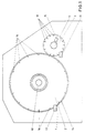
- the shaft 10 of the heating roller 2 and the shaft 11 of the pressure roller 3 are mounted in the stands 1 of the calender.
- a DC motor 12 drives the shaft 10 of the heating roller 2 and a DC motor 13 drives the shaft 11 of the pressure roller 3.
- the shaft 11 of the pressure roller 3 is slidably mounted in the calender stand 1, the shaft 11 is pressed in the direction of the shaft 10 by a hydraulically generated force.
- the location of the shaft 11 is dependent on the thickness of the sealing plate 14 built up on the heating roller 2.
- the position of the shaft 11 of the pressure roller 3 is determined by an encoder 15.
- the heating roller 2 is provided on its circumference with marks 16 arranged at the same distance.
- a sensor 17 is provided, which emits a pulse each time a mark 16 passes, which is fed to the input 5 of the processor 9.
- marks 18 are attached to the pressure roller 3, the passage of which is sensed by an encoder 19 which is connected to the input 4 of the processor 9.
- the third input 6 of the processor 9 is connected to the encoder 15.
- the processor has two outputs 7 and 8, of which one output 7 is connected to the control device 20 for the motor 13 and the other output 8 to the control device 21 for the motor 12.
- buttons 22 for scanning the surface of the plate 14 built on the heating roller 2 which are connected to a further input 23 of the processor 9.
Landscapes
- Engineering & Computer Science (AREA)
- Mechanical Engineering (AREA)
- Casting Or Compression Moulding Of Plastics Or The Like (AREA)
Claims (6)
- Calandre pour la fabrication de plaques de joints qui comprend un rouleau chauffant (2) de grand diamètre, monté dans des paliers fixes, entraîné par moteur, et un rouleau de pression (3) non chauffé, de plus petit diamètre, monté dans des paliers coulissants, à l'encontre d'une force de mise en pression, et entraîné par un moteur distinct,
caractérisée
en ce que les deux moteurs d'entraînement (12, 13) des deux rouleaux sont commandés par un processeur (9) commandé par programme, à une (6) des entrées duquel est connecté un capteur de déplacement (15) qui capte la translation de l'axe (11) ou des paliers de l'axe du rouleau de pression (3), tandis qu'à sa deuxième entrée (5), est connecté un capteur (17) destiné à constater le passage de marques (16) prévues sur le rouleau chauffant (2) ou sur son arbre d'entraînement,
et qu'à sa troisième entrée (4), est connecté un capteur (19) destiné à constater le passage de marques (18) prévues sur le rouleau de pression (3) ou sur son arbre d'entraînement (18), et aux deux sorties (7, 8) duquel sont connectés des dispositifs de commande (20, 21) prévus pour la vitesse de rotation des deux moteurs (12, 13) d'entraînement des rouleaux. - Calandre selon la revendication 1,
caractérisée
par des circuits de commande à fonctionnement numérique inclus dans le processeur (9). - Calandre selon la revendication 1,
caractérisée
par une commande en poursuite pour le rouleau de pression (3). - Calandre selon la revendication 1,
caractérisée
en ce que les capteurs (17, 19) actionnés par les marques (16, 18) prévues sur les rouleaux (2, 3) sont des capteurs incrémentaux. - Capteurs selon la revendication 1,
caractérisée
par un commutateur (22) servant à établir le synchronisme des rouleaux ou un écart réglable déterminé entre la vitesse de rotation du rouleau de pression (3) et la vitesse de rotation du rouleau chauffant (2). - Calandre selon la revendication 1,
caractérisée
par des palpeurs (22) servant à palper la surface de la plaque (14) formée sur le rouleau chauffant (2), qui sont connectés à une autre entrée (23) du processeur (9).
Applications Claiming Priority (2)
| Application Number | Priority Date | Filing Date | Title |
|---|---|---|---|
| DE4011410 | 1990-04-09 | ||
| DE4011410A DE4011410C2 (de) | 1990-04-09 | 1990-04-09 | Kalander zur Herstellung von Dichtungsplatten |
Publications (3)
| Publication Number | Publication Date |
|---|---|
| EP0451494A2 EP0451494A2 (fr) | 1991-10-16 |
| EP0451494A3 EP0451494A3 (en) | 1992-03-11 |
| EP0451494B1 true EP0451494B1 (fr) | 1994-06-01 |
Family
ID=6404044
Family Applications (1)
| Application Number | Title | Priority Date | Filing Date |
|---|---|---|---|
| EP91103201A Expired - Lifetime EP0451494B1 (fr) | 1990-04-09 | 1991-03-04 | Calandre pour la fabrication de plaques d'étanchéité |
Country Status (4)
| Country | Link |
|---|---|
| US (1) | US5318430A (fr) |
| EP (1) | EP0451494B1 (fr) |
| JP (1) | JPH04226311A (fr) |
| DE (2) | DE4011410C2 (fr) |
Families Citing this family (13)
| Publication number | Priority date | Publication date | Assignee | Title |
|---|---|---|---|---|
| KR200250328Y1 (ko) * | 2001-07-24 | 2001-11-22 | (주)제이브이메디 | 약제분포기용 포장지의 동력배출장치 |
| TWI428682B (zh) * | 2005-03-22 | 2014-03-01 | Kuraray Co | 成型薄片及柱狀透鏡薄片之製造方法、以及其等之製造裝置 |
| KR100659909B1 (ko) * | 2005-08-25 | 2006-12-20 | (주)제이브이엠 | 약제 자동 포장 시스템 |
| KR100744427B1 (ko) * | 2006-06-05 | 2007-08-01 | (주)제이브이엠 | 약제자동포장장치용 카세트 인식장치 및 그 방법 |
| KR100807992B1 (ko) * | 2006-06-21 | 2008-02-28 | (주)제이브이엠 | 보조트레이 정보 인식장치 및 그 방법 |
| KR100842177B1 (ko) * | 2006-09-20 | 2008-06-30 | (주)제이브이엠 | 정제자동포장기의 통합 제어 시스템 및 그 방법 |
| KR100708234B1 (ko) * | 2006-09-22 | 2007-04-16 | (주)제이브이엠 | 의약품 수납 캐비닛 |
| KR100800290B1 (ko) * | 2006-11-01 | 2008-02-01 | (주)제이브이엠 | 약제 자동 포장기용 카세트 장치 |
| KR100807994B1 (ko) * | 2006-11-02 | 2008-02-28 | (주)제이브이엠 | 약제 자동 포장기의 라스트호퍼 진동방법 및 장치 |
| KR100767599B1 (ko) * | 2006-11-13 | 2007-10-17 | (주)제이브이엠 | 약제 자동 포장기의 정전보상 운전방법 및 장치 |
| KR100787807B1 (ko) * | 2006-12-22 | 2007-12-21 | (주)제이브이엠 | 약제 자동 포장기의 수동분배트레이 검사방법 및 장치 |
| KR100787806B1 (ko) * | 2006-12-22 | 2007-12-21 | (주)제이브이엠 | 약제 자동 포장기의 분할 포장방법 및 장치 |
| KR100787808B1 (ko) | 2006-12-22 | 2007-12-21 | (주)제이브이엠 | 도어락킹부를 갖는 약제 자동 포장기 |
Family Cites Families (14)
| Publication number | Priority date | Publication date | Assignee | Title |
|---|---|---|---|---|
| FR1376499A (fr) * | 1963-03-19 | 1964-10-31 | Perfectionnements au serrage des cylindres de broyeuses et autres machines à cylindres | |
| US3292208A (en) * | 1963-10-17 | 1966-12-20 | Lab For Electronics Inc | Process control system |
| US3531827A (en) * | 1966-05-13 | 1970-10-06 | Harte & Co Inc | Thickness control system for calendering |
| US3655312A (en) * | 1969-05-02 | 1972-04-11 | Gaf Corp | Apparatus for making embossed foamed surface covering materials |
| US3600747A (en) * | 1969-05-21 | 1971-08-24 | Firestone Tire & Rubber Co | System for calender control |
| US3893795A (en) * | 1970-08-20 | 1975-07-08 | Rowland Dev Corp | Embossing rolls with areas of differential hardness |
| DE2438983A1 (de) * | 1974-08-14 | 1976-03-04 | Berstorff Gmbh Masch Hermann | Mehrwalzenkalander zur herstellung von thermoplastischen folien |
| FI64902C (fi) * | 1976-03-30 | 1984-02-10 | Wiik & Hoeglund | Foerfarande foer kompensering av valsboejningen i en kalander |
| US4319868A (en) * | 1978-12-07 | 1982-03-16 | The Procter & Gamble Company | Apparatus for embossing and perforating a running ribbon of thermoplastic film on a metallic pattern roll |
| US4260578A (en) * | 1979-10-18 | 1981-04-07 | Amf Incorporated | Method and apparatus for making elastomer sheet material |
| US4302478A (en) * | 1980-06-09 | 1981-11-24 | J. R. Simplot Company | Method of shaping potato dough |
| JPS58141807A (ja) * | 1982-02-15 | 1983-08-23 | Mitsubishi Electric Corp | 自動板厚制御装置 |
| US4519757A (en) * | 1984-01-17 | 1985-05-28 | Magna-Graphics Corporation | Web surface treating apparatus |
| US4810179A (en) * | 1988-01-27 | 1989-03-07 | Marshall & Williams Company | Force indicator for casting machines |
-
1990
- 1990-04-09 DE DE4011410A patent/DE4011410C2/de not_active Expired - Fee Related
-
1991
- 1991-03-04 DE DE59101752T patent/DE59101752D1/de not_active Expired - Fee Related
- 1991-03-04 EP EP91103201A patent/EP0451494B1/fr not_active Expired - Lifetime
- 1991-04-08 JP JP3103823A patent/JPH04226311A/ja active Pending
-
1993
- 1993-02-23 US US08/022,793 patent/US5318430A/en not_active Expired - Fee Related
Also Published As
| Publication number | Publication date |
|---|---|
| DE59101752D1 (de) | 1994-07-07 |
| EP0451494A3 (en) | 1992-03-11 |
| US5318430A (en) | 1994-06-07 |
| DE4011410C2 (de) | 1994-06-09 |
| DE4011410A1 (de) | 1991-10-10 |
| JPH04226311A (ja) | 1992-08-17 |
| EP0451494A2 (fr) | 1991-10-16 |
Similar Documents
| Publication | Publication Date | Title |
|---|---|---|
| EP0451494B1 (fr) | Calandre pour la fabrication de plaques d'étanchéité | |
| DE4009917C1 (fr) | ||
| EP2934844B1 (fr) | Appareil de lissage et procédé de fabrication d' un film en matière plastique | |
| EP0976495B1 (fr) | Meuleuse à bande abrasive | |
| DE19950534B4 (de) | Spritzgießmaschine | |
| DE102007062936A1 (de) | Vorrichtung zum Rotationsschneiden | |
| EP0694493B2 (fr) | Dispositif de pliage | |
| DE3153304C2 (fr) | ||
| DE68903909T2 (de) | Verfahren und gleitfertiger zum giessen eines oder mehrerer nebeneinander gelegter betongegenstaende. | |
| DE102009000630A1 (de) | Flexibelbogen | |
| DE102005060578A1 (de) | Vorrichtung zum Rotationsschneiden | |
| DE19544988C2 (de) | Positioniersteuerung im Glättwerk | |
| DE3912303C2 (de) | Kalander für die Herstellung von Dichtungsplatten | |
| DE3207856A1 (de) | Walzpresse zur herstellung von granulat oder formlingen | |
| CH647431A5 (en) | Apparatus and process for the cold rolling of sections by rolling on the circumference of a simultaneously rotating workpiece | |
| DE3707745C2 (de) | Verfahren und Anlage zur Steuerung der Vermahlung einer teigig-pastösen Masse | |
| DE9004096U1 (de) | Kalander zur Herstellung von Dichtungsplatten | |
| EP0452652B1 (fr) | Procédé et appareil pour produire une plaque d'étanchéité sur une calandre | |
| AT409105B (de) | Verfahren zum regeln des gegendruckes in einer einrichtung zum plastifizieren und dosieren von kunststoff | |
| DE1912392A1 (de) | Mechanische-elektrische Einrichtung zum UEberwachen der Parallelverstellung der Walzen eines Kalanders | |
| DE4111220C2 (de) | Vorrichtung zur Steuerung eines Kalanders für die Herstellung von Dichtungsplatten | |
| DE2519508A1 (de) | Einstellvorrichtung fuer den abstand zwischen walzen | |
| EP0451495B1 (fr) | Dispositif de contrôle d'une calandre pour la fabrication de plaques d'étanchéité | |
| DE3441305C2 (fr) | ||
| DE2050539B2 (de) | Falzmaschine für Leder u.dgl |
Legal Events
| Date | Code | Title | Description |
|---|---|---|---|
| PUAI | Public reference made under article 153(3) epc to a published international application that has entered the european phase |
Free format text: ORIGINAL CODE: 0009012 |
|
| AK | Designated contracting states |
Kind code of ref document: A2 Designated state(s): DE FR GB IT |
|
| PUAL | Search report despatched |
Free format text: ORIGINAL CODE: 0009013 |
|
| AK | Designated contracting states |
Kind code of ref document: A3 Designated state(s): DE FR GB IT |
|
| 17P | Request for examination filed |
Effective date: 19920320 |
|
| 17Q | First examination report despatched |
Effective date: 19930927 |
|
| RAP1 | Party data changed (applicant data changed or rights of an application transferred) |
Owner name: PAUL TROESTER MASCHINENFABRIK |
|
| GRAA | (expected) grant |
Free format text: ORIGINAL CODE: 0009210 |
|
| ITF | It: translation for a ep patent filed | ||
| AK | Designated contracting states |
Kind code of ref document: B1 Designated state(s): DE FR GB IT |
|
| REF | Corresponds to: |
Ref document number: 59101752 Country of ref document: DE Date of ref document: 19940707 |
|
| GBT | Gb: translation of ep patent filed (gb section 77(6)(a)/1977) |
Effective date: 19940610 |
|
| ET | Fr: translation filed | ||
| PLBE | No opposition filed within time limit |
Free format text: ORIGINAL CODE: 0009261 |
|
| STAA | Information on the status of an ep patent application or granted ep patent |
Free format text: STATUS: NO OPPOSITION FILED WITHIN TIME LIMIT |
|
| 26N | No opposition filed | ||
| PGFP | Annual fee paid to national office [announced via postgrant information from national office to epo] |
Ref country code: GB Payment date: 19990224 Year of fee payment: 9 |
|
| PGFP | Annual fee paid to national office [announced via postgrant information from national office to epo] |
Ref country code: FR Payment date: 19990225 Year of fee payment: 9 |
|
| PGFP | Annual fee paid to national office [announced via postgrant information from national office to epo] |
Ref country code: DE Payment date: 19990301 Year of fee payment: 9 |
|
| PG25 | Lapsed in a contracting state [announced via postgrant information from national office to epo] |
Ref country code: GB Free format text: LAPSE BECAUSE OF NON-PAYMENT OF DUE FEES Effective date: 20000304 |
|
| GBPC | Gb: european patent ceased through non-payment of renewal fee |
Effective date: 20000304 |
|
| PG25 | Lapsed in a contracting state [announced via postgrant information from national office to epo] |
Ref country code: FR Free format text: LAPSE BECAUSE OF NON-PAYMENT OF DUE FEES Effective date: 20001130 |
|
| REG | Reference to a national code |
Ref country code: FR Ref legal event code: ST |
|
| PG25 | Lapsed in a contracting state [announced via postgrant information from national office to epo] |
Ref country code: DE Free format text: LAPSE BECAUSE OF NON-PAYMENT OF DUE FEES Effective date: 20010103 |
|
| PG25 | Lapsed in a contracting state [announced via postgrant information from national office to epo] |
Ref country code: IT Free format text: LAPSE BECAUSE OF NON-PAYMENT OF DUE FEES;WARNING: LAPSES OF ITALIAN PATENTS WITH EFFECTIVE DATE BEFORE 2007 MAY HAVE OCCURRED AT ANY TIME BEFORE 2007. THE CORRECT EFFECTIVE DATE MAY BE DIFFERENT FROM THE ONE RECORDED. Effective date: 20050304 |