EP0451495A2 - Control apparatus for a calender for making sealing sheets - Google Patents
Control apparatus for a calender for making sealing sheets Download PDFInfo
- Publication number
- EP0451495A2 EP0451495A2 EP91103202A EP91103202A EP0451495A2 EP 0451495 A2 EP0451495 A2 EP 0451495A2 EP 91103202 A EP91103202 A EP 91103202A EP 91103202 A EP91103202 A EP 91103202A EP 0451495 A2 EP0451495 A2 EP 0451495A2
- Authority
- EP
- European Patent Office
- Prior art keywords
- depending
- plate thickness
- counter
- der
- circuits
- Prior art date
- Legal status (The legal status is an assumption and is not a legal conclusion. Google has not performed a legal analysis and makes no representation as to the accuracy of the status listed.)
- Granted
Links
Images

Classifications
-
- B—PERFORMING OPERATIONS; TRANSPORTING
- B30—PRESSES
- B30B—PRESSES IN GENERAL
- B30B3/00—Presses characterised by the use of rotary pressing members, e.g. rollers, rings, discs
- B30B3/04—Presses characterised by the use of rotary pressing members, e.g. rollers, rings, discs co-operating with one another, e.g. with co-operating cones
-
- B—PERFORMING OPERATIONS; TRANSPORTING
- B30—PRESSES
- B30B—PRESSES IN GENERAL
- B30B15/00—Details of, or accessories for, presses; Auxiliary measures in connection with pressing
- B30B15/26—Program-control arrangements
Definitions
- the invention relates to a device for controlling a calender for the production of sealing plates, which is equipped with a heating roller of large diameter and a separately motor-driven counter-pressure roller of smaller diameter, with two plate thickness measuring transducers, a rotational speed sensor, revolution counters, as well as engine speed regulators and pressing force generators and counter bending force generators.
- sealing plate calenders which have a heated roller on which the plates are rolled and vulcanized, and a cooled roller, which serves as a pressure roller for the assembly, are used for the production of fiber-reinforced flat seals, which are required at numerous points in technology is usually pressed hydraulically.
- the seals are made from a mixture of rubber and fibers made processable in solvents, which give the strength of the finished product, produced.
- Asbestos fibers have traditionally been used as reinforcement, since the manufacture and use of the panels excluded other fibers for thermal reasons.
- asbestos is increasingly undesirable due to health hazards and has recently been replaced, if possible, with high-strength and thermally resistant synthetic fibers.
- the invention avoids the disadvantages of the prior art.
- the invention has for its object to provide conditions for the proper control of the manufacturing process of synthetic fiber reinforced sealing plates, in which a consistently high quality of the sealing plates produced is achieved.
- the invention achieves this in that the operator has left the machine and process control that has been generally customary up to now and is switched to automatic process control.
- a computer program is developed which takes into account all the parameters mentioned and thereby enables the operator to concentrate on the monitoring of the system and its optimal loading with mass and merely to monitor the other entire manufacturing process.
- the processor is connected to temperature sensors for the surface temperature is connected to the plate being manufactured and a circuit is provided for linking the functions of the process specifications as a function of the surface temperature. Because the surface temperature gives a special indication of the solvent content of the applied layer and the degree of vulcanization.
- the shaft 10 of the heating roller 2 and the shaft 11 of the pressure roller 3 are mounted in the stands 1 of the calender.
- a DC motor 12 drives the shaft 10 of the heating roller 2 and a DC motor 13 drives the shaft 11 of the pressure roller 3.
- the shaft 11 of the pressure roller 3 is slidably mounted in the calender stand 1, by means of a force generated by the hydraulic pressing device 24, the shaft 11 is pressed in the direction of the shaft 10.
- the location of the shaft 11 is dependent on the thickness of the sealing plate 14 built up on the heating roller 2.
- the position of the shaft 11 of the pressure roller 3 is determined by an encoder 15.
- the heating roller 2 is provided on its circumference with marks 16 arranged at the same distance.
- a sensor 17 is provided, each of which passes when one passes Mark 16 emits a pulse which is fed to the input 5 of the processor 9.
- marks 18 are attached to the pressure roller 3, the passage of which is sensed by an encoder 19 which is connected to the input 4 of the processor 9.
- the third input 6 of the processor 9 is connected to the encoder 15.
- the processor has two outputs 7 and 8, of which one output 7 is connected to the control device 20 for the motor 13 and the other output 8 to the control device 21 for the motor 12.
- Pipes 26 lead from the heating device 25 into the heating roller 2.
- a temperature sensor 27 is arranged in these pipes, the output signals of which are introduced into the input 28 of the processor 9.
- the pressure roller 3 is connected to the cooling device 30 via pipes 29.
- a temperature sensor 31 arranged in the tubes 29 is connected to the input 32 of the processor 9. From the output 33 a control line leads to the heating device 25, from the output 34 of the processor 9 a control line leads to the cooling device 30.
- Another output 35 of the processor 9 leads to the control device 36 of the hydraulic pressing device 24 on the pressure roller 3. From the output 37 of the processor 9, a control line leads to the control device 38 of the counter-bending device 39.
- a loading device 40 is arranged, which is connected to the output 41 of the processor 9.
- a device for the solvent supply 42 is provided, the solvent flow of which is controlled by the control device 43, which is connected to the output 44 of the processor. Furthermore, a material distribution device 45 is provided, the control of which is connected to the output 46 of the processor.
- Various memories 47 in which recipes and / or procedures are recorded, are connected to the input 49 of the processor 9 via the selection device 48.
- the output 50 of the processor which leads to the memory 47, is provided for the recording of programs according to a manually performed control.
Landscapes
- Engineering & Computer Science (AREA)
- Mechanical Engineering (AREA)
- Casting Or Compression Moulding Of Plastics Or The Like (AREA)
Abstract
Description
Die Erfindung betrifft eine Vorrichtung zur Steuerung eines Kalanders für die Herstellung von Dichtungsplatten, der mit einer Heizwalze großen Durchmessers und einer gesondert motorisch angetriebenen Gegendruckwalze kleineren Durchmessers, mit zwei Plattendickemeßgebern, einem Drehgeschwindigkeitsgeber, Umdrehungszählern sowie Motordrehzahlreglern und Andrückkrafterzeuger und Gegenbiegekrafterzeuger ausgestattet ist.The invention relates to a device for controlling a calender for the production of sealing plates, which is equipped with a heating roller of large diameter and a separately motor-driven counter-pressure roller of smaller diameter, with two plate thickness measuring transducers, a rotational speed sensor, revolution counters, as well as engine speed regulators and pressing force generators and counter bending force generators.
Für die Herstellung von faserverstärkten Flachdichtungen, die in der Technik an zahlreichen Stellen benötigt werden, benutzt man sogenannte Dichtungsplattenkalander, die eine beheizte Walze besitzen, auf der die Platten aufgewalzt und ausvulkanisiert werden, und eine gekühlte Walze, die als Anpreßwalze für den Aufbau dient und zumeist hydraulisch angepreßt wird.So-called sealing plate calenders, which have a heated roller on which the plates are rolled and vulcanized, and a cooled roller, which serves as a pressure roller for the assembly, are used for the production of fiber-reinforced flat seals, which are required at numerous points in technology is usually pressed hydraulically.
Die Dichtungen werden dabei aus einem Gemisch von in Lösungsmitteln verarbeitbar gemachtem Kautschuk und Fasern, weiche die Festigkeit des Fertigproduktes ergeben, hergestellt. Traditionell wurden als Festigkeitsträger Asbestfasern verwendet, da die Plattenherstellung und -verwendung aus thermischen Gründen andere Fasern ausschlossen. Asbest ist jedoch aus Gründen der Gesundheitsgefahren in zunehmendem Maße unerwünscht und wird in neuerer Zeit, sofern möglich, durch hochfeste und thermisch beständige Kunstfasern ersetzt.The seals are made from a mixture of rubber and fibers made processable in solvents, which give the strength of the finished product, produced. Asbestos fibers have traditionally been used as reinforcement, since the manufacture and use of the panels excluded other fibers for thermal reasons. However, asbestos is increasingly undesirable due to health hazards and has recently been replaced, if possible, with high-strength and thermally resistant synthetic fibers.
An die Präzision der Walzenrundlaufgenauigkeit, der Walzenoberflächengüte, der Temperaturhöhe und -genauigkeit, der gleichmäßigen Walzenandruckkraft und vor allem auch der hohen Genauigkeit der beiden Walzenumfangsgeschwindigkeiten (des Gleichlaufes) werden bei Verwendung der Kunstfasern sehr hohe Anforderungen gestellt.The precision of the roll concentricity, the roll surface quality, the temperature level and accuracy, the uniform roll pressure force and, above all, the high accuracy of the two roll peripheral speeds (synchronism) make very high demands when using synthetic fibers.
Bei der Dichtungsplattenherstellung auf dem Kalander haben neben den bereits erwähnten Maschineneigenschaften noch zahlreiche Details Einfluß, so z.B.:
- die Temperaturhöhe der Heizwalze. Sie ist entscheidend für die Vulkanisationsleistung und damit für die Aufbaugeschwindigkeit der Platte.
- die Temperaturgenauigkeit. Sie hat Bedeutung in Bezug auf die Gleichmäßigkeit der Ausvulkanisation.
- die Arbeitsgeschwindigkeit der Walzen. Sie hängt von verschiedenen Parametern, wie z.B. der Haftung der Masse auf der Walzenoberfläche ab und ergibt unter Berücksichtigung der Vulkanisationsgeschwindigkeit die Zahl der Plattenüberrollungen während des Zyklus durch die Anpreßwalze und bestimmt damit die Verdichtung und Qualität der Platte.
- der Druck in den Preßzylinder links/rechts der Anpreßwalze. Er ist wichtig für die Gleichmäßigkeit der Dicke der erzeugten Platte.
- der Linien-Anpreßdruck der Anpreßwalze. Er ist entscheidend wichtig für die Verdichtung der Platte.
- Korrektur der Walzendurchbiegung. Zur Erzielung optimaler Bedingungen wird eine Gegenbiegevorrichtung für die Anpreßwalze angewendet, die entsprechend der jeweiligen Anpreßkraft eingestellt wird.
- die Anpreßkraft. Sie muß je nach der Mischungssorte und der Plattendicke optimiert werden.
- die Geschwindigkeitseinstellung beider einzeln angetriebener Walzen zueinander, die normalerweise genau gleich sein muß, gelegentlich aber eine extrem geringe, aber genaue Friktionseinstellung bedingt.
- die Beschickung der Masse in Bezug auf die Menge und die optimale Verteilung über die Länge des Walzenspaltes, wodurch sich die Gleichmäßigkeit der Plattentoleranz über die Arbeitsbreite ergibt.
- eine Veränderung der Parameter nach Beginn des Plattenaufbaues in Abhängigkeit der zunehmenden Plattendicke, z.B. des Preßdruckes, der Geschwindigkeit mit dickenbedingter Abnahme der Vulkanisationsgeschwindigkeit, Zahl der Überrollungen u.a.m.
- the temperature level of the heating roller. It is decisive for the vulcanization performance and thus for the speed of assembly of the plate.
- the temperature accuracy. It is important with regard to the uniformity of the vulcanization.
- the working speed of the rollers. It depends on various parameters, such as the adhesion of the mass to the roll surface and, taking into account the speed of vulcanization, results in the number of plate rolls during the cycle by the pressure roller and thus determines the compression and quality of the plate.
- the pressure in the press cylinder left / right of the pressure roller. It is important for the uniformity of the thickness of the plate produced.
- the line pressure of the pressure roller. It is of crucial importance for the compression of the plate.
- Correction of roll deflection. To achieve optimal conditions, a counter-bending device is used for the pressure roller, which is adjusted according to the respective pressure force.
- the contact pressure. It must be optimized depending on the type of mixture and the plate thickness.
- the speed setting of both individually driven rollers to each other, which normally has to be exactly the same, but occasionally requires an extremely low but precise friction setting.
- the feeding of the mass in relation to the quantity and the optimal distribution over the length of the nip, which results in the uniformity of the plate tolerance over the working width.
- a change in the parameters after the start of the plate build-up as a function of the increasing plate thickness, for example the pressing pressure, the speed with a decrease in the vulcanization speed due to the thickness, the number of rollovers, etc.
Bei den traditionellen Werkstoffen der Dichtungsplatten, also bei denen mit Asbestfaserverstärkung, genügte zumeist in Bezug auf die Führung dieses komplizierten Arbeitsprozesses die Einstellung und die laufende Korrektur der Produktionsparameter durch den Bedienungsmann, der auch die Beschickung des Kalanders vornahm und aufgrund seiner Erfahrung alle anderen Werte nach Bedarf so gut es ging optimierte.With the traditional materials of the sealing plates, i.e. those with asbestos fiber reinforcement, the adjustment and the continuous correction of the production parameters by the operator, who also loaded the calender and based on his experience, usually sufficed with regard to the management of this complicated work process Need optimized as best as possible.
Aufgrund der Forderung nach asbestfreien Dichtungsplatten und der dadurch bedingten Einführung von hochfesten temperaturbeständigen Kunstfasern ist aber die Verarbeitung der Mischungen sehr viel schwieriger geworden. Insbesondere ist die Auffindung und Einhaltung optimaler Arbeitsparameter vor allem während des Plattenaufbaues teilweise so problematisch geworden, daß nur ganz besonders erfahrene Bedienungsleute noch in der Lage sind, einwandfreie Dichtungsplatten herzustellen. Trotzdem entsteht bei der Plattenherstellung sehr viel Ausschuß, der wirtschaftlich nicht tragbar ist.Due to the requirement for asbestos-free sealing sheets and the consequent introduction of high-strength However, processing the mixtures has become much more difficult with temperature-resistant synthetic fibers. In particular, finding and maintaining optimal working parameters has become so problematic, especially during plate construction, that only very experienced operators are still able to produce perfect sealing plates. Nevertheless, there is a lot of rejects in the manufacture of plates, which is not economically viable.
Die Erfindung vermeidet die Nachteile des Standes der Technik. Der Erfindung liegt die Aufgabe zugrunde, Voraussetzungen für die einwandfreie Steuerung des Herstellungsverfahrens von kunstfaserverstärkten Dichtungsplatten zu schaffen, bei dem eine stets gleichbleibende hohe Qualität der erzeugten Dichtungsplatten erzielt wird.The invention avoids the disadvantages of the prior art. The invention has for its object to provide conditions for the proper control of the manufacturing process of synthetic fiber reinforced sealing plates, in which a consistently high quality of the sealing plates produced is achieved.
Die Erfindung erreicht dieses dadurch, daß die bisher generell übliche Maschinen- und Prozeßsteuerung durch den Bedienungsmann verlassen wird und auf eine automatische Prozeßführung übergegangen wird.The invention achieves this in that the operator has left the machine and process control that has been generally customary up to now and is switched to automatic process control.
Die Erfindung besteht in der Verwendung eines Prozessors, an dessen Eingänge
- die Umdrehungszähler
- die Temperaturgeber für das Heizmittel und/oder Kühlmittel
- die Drehgeschwindigkeitsgeber
- die Plattendickemeßgeber
und an dessen Ausgänge
- die Motordrehgeschwindigkeitsregler und/oder
- die Heizungssteuerung der Heizwalze und/oder
- die Kühlungssteuerung der Andrückwalze und/oder
- die Andrückkrafterzeuger und/oder
- die Gegenbiegekrafterzeuger und/oder
- eine Lösungsmittelzufuhrvorrichtung und/oder
- eine Materialzufuhrvorrichtung und/oder
- eine Vorrichtung zur Materialverteilung
angeschlossen sind, und der Schaltkreise für Funktionsverknüpfungen
- Motorendrehzahlen in Abhängigkeit von der Zeit und/oder ausgeführten Umdrehungen und/oder
- Heizmittel- und/oder Kühlmitteltemperatur in Abhängigkeit von der Zeit und/oder ausgeführter Umdrehungen und/oder Plattendicke und/oder
- Drehgeschwindigkeiten in Abhängigkeit von der Zeit und/oder Plattendicke und/oder ausgeführter Umdrehungen und/oder Andrückkraft und/oder
- Lösungsmittelzufuhr in Abhängigkeit von der Zeit und/oder Plattendicke, und/oder Plattendickenwuchsgeschwindigkeit und/oder
- Gegenbiegekrafterzeugung in Abhängigkeit von der Plattendicke und/oder
- Materialzufuhr in Abhängigkeit von der Plattenwuchsgeschwindigkeit und/oder
- Materialverteilung in Abhängigkeit von der Zeit und/oder der Plattenwuchsgeschwindigkeit und/oder
- Drehgeschwindigkeitsdifferenz der Walzen in Abhängigkeit von der Zeit und/oder Plattendicke und/oder Drehgeschwindigkeit
aufweist.The invention consists in the use of a processor at its inputs
- the revolution counter
- the temperature sensors for the heating medium and / or cooling medium
- the speed encoder
- the plate thickness gauges
and at its exits
- the engine speed controller and / or
- the heating control of the heating roller and / or
- the cooling control of the pressure roller and / or
- the pressure force generator and / or
- the counter bending force generator and / or
- a solvent supply device and / or
- a material feed device and / or
- a device for material distribution
are connected, and the circuits for function links
- Engine speeds depending on the time and / or revolutions carried out and / or
- Heating medium and / or coolant temperature depending on the time and / or revolutions carried out and / or plate thickness and / or
- Rotational speeds depending on the time and / or plate thickness and / or revolutions carried out and / or pressing force and / or
- Solvent supply depending on the time and / or plate thickness, and / or plate thickness growth rate and / or
- Counter bending force generation depending on the plate thickness and / or
- Material supply depending on the plate growth rate and / or
- Material distribution depending on the time and / or the rate of plate growth and / or
- Difference in rotational speed of the rollers as a function of time and / or plate thickness and / or rotational speed
having.
Mit dieser Vorrichtung zur Steuerung des Kalanders wird die Abhängigkeit von der Plattenart, deren Mischungsaufbau und der vorgesehenen Plattendicke sowie die Zahl der für ein optimales Ergebnis erforderlichen Überrollungen ein Prozeßführungsprogramm entwickelt, welches sich nach zuvor theoretisch oder praktisch ermittelten optimalen Werten ausrichtet und folgende Parameter einbezieht:
- Startbedingung bei Beginn der Beschickung,
- zunehmende Plattendicke bis zum Sollwert der fertigen Platte,
- Walzentemperaturen der Heizwalze und der gekühlten Preßwalze,
- Zahl der Überrollungen im Arbeitszyklus,
- Arbeitsgeschwindigkeit des Kalanders beim Start und Veränderung derselben mit zunehmender Plattendicke,
- Gleichlaufeinstellung der beiden Walzen bzw. optimale (extrem geringe) Friktionseinstellung in Abhängigkeit von Mischung, zunehmender Plattendicke und Arbeitstemperatur,
- Preßkraft der gekühlten Andrückwalze ebenfalls als Funktion von Mischung, Plattendicke und Arbeitstemperatur,
- Gegenbiegung der Andrückwalze entsprechend der eingestellten Preßkraft zwecks Erzielung gleichmäßiger Plattendicke über die Arbeitsbreite gesehen.
- Start condition at the start of loading,
- increasing plate thickness up to the target value of the finished plate,
- Roll temperatures of the heating roll and the cooled press roll,
- Number of rollovers in the work cycle,
- Working speed of the calender when starting and changing it with increasing plate thickness,
- Synchronization setting of the two rollers or optimal (extremely low) friction setting depending on the mixture, increasing plate thickness and working temperature,
- Pressing force of the cooled pressure roller also as a function of mixture, plate thickness and working temperature,
- Counter-bending of the pressure roller according to the set pressing force in order to achieve uniform plate thickness over the working width.
Dabei wird erfindungsgemäß ein Computerprogramm erarbeitet, welches alle erwähnten Parameter berücksichtigt und dadurch der Bedienungsperson ermöglicht, sich auf die Überwachung der Anlage und deren optimale Beschickung mit Masse zu konzentrieren und den sonstigen gesamten Fertigungsprozeß lediglich zu überwachen.According to the invention, a computer program is developed which takes into account all the parameters mentioned and thereby enables the operator to concentrate on the monitoring of the system and its optimal loading with mass and merely to monitor the other entire manufacturing process.
Mit Hilfe bestimmter Programmschritte kann dabei erreicht werden, daß bestimmte Arbeitsschritte, die ein Bedienungsmann nur nacheinander ausführen kann, durch die vorgesehenen Schaltungen bei Bedarf zeitlich optimiert, also gleichzeitig ausgeführt werden können.With the help of certain program steps it can be achieved that certain work steps that an operator can only execute one after the other, can be optimized in terms of time if necessary, that is, can be executed simultaneously, using the circuits provided
Wichtig ist, daß den Eingangsgrößen oder Schaltkreisen der Dickenmessung und/oder Messung der Anzahl der Umrollungen die Schaltkreise bzw. die Prozeßeinflußgrößen der Drehzahlverstellung, Friktionsverstellung, Andruckverstellung rechts/links Gegenbiegung nachgeschaltet sind. Denn es ist grundsätzlich so, daß es für die Durchführung einer optimalen Prozeßsteuerung notwendig ist, von einer dicken Messung und/oder von der Messung der Anzahl der Umrollungen auszugehen und dann aufgrund des eingegebenen Programms die Schaltkreise der Drehzahlverstellung, Friktionsverstellung, Andruckverstellung rechts/links und der Gegenbiegung zu steuern.It is important that the input variables or circuits of the thickness measurement and / or measurement of the number of rewindings are followed by the circuits or the process influencing variables of the speed adjustment, friction adjustment, pressure adjustment right / left counter-bending. Because it is fundamentally such that it is necessary to carry out an optimal process control, to start from a thick measurement and / or from the measurement of the number of rewindings and then, based on the program entered, the circuits of the speed adjustment, friction adjustment, pressure adjustment right / left and to control the counterbend.
Vorteilhaft ist es, wenn ein Eingang und/oder ein Ausgang des Prozessors und deren Steuerung (Software) mit einem Datenspeicher verbunden ist. Von besonderem Wert ist noch die ebenfalls erfindungsgemäß vorgesehene Möglichkeit, eine bestimmte Plattentype mit empirisch gefundener guter Arbeitseinstellung zu fahren und dabei gleichzeitig die genutzten Werte automatisch als Programm für die Wiederholung des durchgeführten Produktionsprozesses zu speichern. Das automatische Prozeßführungssystem erlaubt es, eine praktisch beliebige Zahl von Programmen zu speichern und damit die gesamte Fertigung langfristig qualitativ zu sichern. Selbstverständlich ist es dabei auch möglich, im Zuge der Qualitätssicherung die Herstellungsgüte aller erzeugten Platten zu dokumentieren.It is advantageous if an input and / or an output of the processor and its control (software) is connected to a data memory. Of particular value is the possibility also provided according to the invention of driving a certain plate type with an empirically found good work attitude and at the same time automatically storing the used values as a program for repeating the production process carried out. The automatic process control system makes it possible to save virtually any number of programs and thus ensure the long-term quality of the entire production. Of course, it is also possible to document the manufacturing quality of all the plates produced as part of quality assurance.
Zu besonders guten Ergebnissen gelangt man, wenn der Prozessor an Temperaturfühler für die Oberflächentemperatur der in der Herstellung befindlichen Platte angeschlossen ist und ein Schaltkreis für die Funktionsverknüpfung der Prozeßvorgaben in Abhängigkeit von der Oberflächentemperatur vorgesehen ist. Denn die Oberflächentemperatur gibt einen besonderen Hinweis auf den Lösungsmittelgehalt der aufgetragenen Schicht und auf den Grad der Vulkanisation.Particularly good results can be achieved if the processor is connected to temperature sensors for the surface temperature is connected to the plate being manufactured and a circuit is provided for linking the functions of the process specifications as a function of the surface temperature. Because the surface temperature gives a special indication of the solvent content of the applied layer and the degree of vulcanization.
Das Wesen der Erfindung ist nachstehend anhand eines in der Zeichnung schematisch dargestellten Ausführungsbeispieles näher erläutert. Es zeigen:
- Fig. 1
- eine schematische Darstellung des Kalanders in Frontansicht,
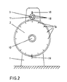
- Fig. 2
- eine Stirnseitenansicht des Kalanders.
- Fig. 1
- a schematic representation of the calender in front view,
- Fig. 2
- an end view of the calender.
In den Ständern 1 des Kalanders ist die Welle 10 der Heizwalze 2 und die Welle 11 der Andrückwalze 3 gelagert. Ein Gleichstrommotor 12 treibt die Welle 10 der Heizwalze 2 und ein Gleichstrommotor 13 die Welle 11 der Andrückwalze 3 an. Die Welle 11 der Andrückwalze 3 ist verschiebbar im Kalanderständer 1 gelagert, durch eine mittels der hydraulischen Preßeinrichtung 24 erzeugte Kraft wird die Welle 11 in Richtung auf die Welle 10 gedrückt. Die örtliche Lage der Welle 11 ist abhängig von der Dicke der auf der Heizwalze 2 aufgebauten Dichtungsplatte 14. Die Lage der Welle 11 der Andrückwalze 3 wird von einem Geber 15 festgestellt.The
Die Heizwalze 2 ist an ihrem Umfang mit im gleichen Abstand angeordneten Marken 16 versehen. Es ist ein Geber 17 vorgesehen, welcher jeweils beim Vorbeilauf einer Marke 16 einen Impuls abgibt, welcher dem Eingang 5 des Prozessors 9 zugeführt wird. Entsprechend sind Marken 18 an der Andrückwalze 3 angebracht, deren Vorbeilauf von einem Geber 19 abgetastet wird, welcher an den Eingang 4 des Prozessors 9 angeschlossen ist.The
Der dritte Eingang 6 des Prozessors 9 ist an den Geber 15 angeschlossen.The
Der Prozessor hat zwei Ausgänge 7 und 8, von denen der eine Ausgang 7 an die Steuervorrichtung 20 für den Motor 13 und der andere Ausgang 8 an die Steuervorrichtung 21 für den Motor 12 angeschlossen ist.The processor has two
Es sind weitere Taster 22 für das Abtasten der Oberfläche der auf der Heizwalze 2 aufgebauten Platte 14 zum Zwecke der Messung der Dicke der Platte 14 vorgesehen, die an einen weiteren Eingang 23 des Prozessors 9 angeschlossen sind.There are
Von der Heizvorrichtung 25 führen Rohre 26 in die Heizwalze 2. In diesen Rohren ist ein Temperaturgeber 27 angeordnet, dessen Ausgangssignale in den Eingang 28 des Prozessors 9 eingeführt werden. Entsprechend ist die Andrückwalze 3 über Rohre 29 mit der Kühlvorrichtung 30 verbunden. Ein in den Rohren 29 angeordneter Temperaturgeber 31 ist an den Eingang 32 des Prozessors 9 angeschlossen. Vom Ausgang 33 führt eine Steuerleitung zur Heizvorrichtung 25, vom Ausgang 34 des Prozessors 9 führt eine Steuerleitung zur Kühlvorrichtung 30. Ein weiterer Ausgang 35 des Prozessors 9 führt zur Steuerungsvorrichtung 36 der hydraulischen Preßeinrichtung 24 an der Andrückwalze 3. Vom Ausgang 37 des Prozessors 9 führt eine Steuerungsleitung zur Steuerungsvorrichtung 38 der Gegenbiegevorrichtung 39. Oberhalb des Walzenspaltes ist eine Beschickungsvorrichtung 40 angeordnet, die an den Ausgang 41 des Prozessors 9 angeschlossen ist. Neben der Beschickungsvorrichtung 40 ist eine Vorrichtung für die Lösungsmittelzufuhr 42 vorgesehen, deren Lösungsmittelzufluß durch die Steuerungsvorrichtung 43 gesteuert wird, die an den Ausgang 44 des Prozessors angeschlossen ist. Weiter ist eine Materialverteilungsvorrichtung 45 vorgesehen, deren Steuerung an den Ausgang 46 des Prozessors angeschlossen ist. Verschiedene Speicher 47, in denen Rezepturen und/oder Verfahrensweisen aufgezeichnet sind, sind über die Auswahlvorrichtung 48 an den Eingang 49 des Prozessors 9 angeschlossen. Für die Aufzeichnung von Programmen gemäß einer manuell durchgeführten Steuerung ist der Ausgang 50 des Prozessors vorgesehen, der zum Speicher 47 führt.
- 11
- KalanderständerCalender stand
- 22nd
- HeizwalzeHeating roller
- 33rd
- AndrückwalzePressure roller
- 44th
- Eingangentrance
- 55
- Eingangentrance
- 66
- Eingangentrance
- 77
- Ausgangexit
- 88th
- Ausgangexit
- 99
- Prozessorprocessor
- 1010th
- Wellewave
- 1111
- Wellewave
- 1212
- Motor-Getriebe-AggregatMotor gear unit
- 1313
- Motor-Getriebe-AggregatMotor gear unit
- 1414
- DichtungsplatteSealing plate
- 1515
- Weg-GeberPath encoder
- 1616
- Markebrand
- 1717th
- Gebergiver
- 1818th
- Markebrand
- 1919th
- Gebergiver
- 2020th
- SteuerungsvorrichtungControl device
- 2121
- SteuerungsvorrichtungControl device
- 2222
- TasterButton
- 2323
- Eingangentrance
- 2424th
- hydraulische Preßeinrichtunghydraulic pressing device
- 2525th
- HeizvorrichtungHeater
- 2626
- RohreTube
- 2727th
- TemperaturgeberTemperature sensor
- 2828
- Eingangentrance
- 2929
- RohreTube
- 3030th
- KühlvorrichtungCooler
- 3131
- TemperaturgeberTemperature sensor
- 3232
- Eingangentrance
- 3333
- Ausgangexit
- 3434
- Ausgangexit
- 3535
- Ausgangexit
- 3636
- SteuerungsvorrichtungControl device
- 3737
- Ausgangexit
- 3838
- SteuerungsvorrichtungControl device
- 3939
- GegenbiegevorrichtungCounter bending device
- 4040
- BeschickungsvorrichtungLoading device
- 4141
- Ausgangexit
- 4242
- LösungsmittelzufuhrSolvent supply
- 4343
- SteuerungsvorrichtungControl device
- 4444
- Ausgangexit
- 4545
- MaterialverteilungsvorrichtungMaterial distribution device
- 4646
- Ausgangexit
- 4747
- SpeicherStorage
- 4848
- AuswahlvorrichtungSelection device
- 4949
- Eingangentrance
- 5050
- Ausgangexit
Claims (5)
der mit einer Heizwalze großen Durchmessers und einer gesondert motorisch angetriebenen Gegendruckwalze kleineren Durchmessers, mit zwei Plattendickemeßgebern, einem Drehgeschwindigkeitsgeber, Umdrehungszählern sowie Motordrehzahlreglern und Andrückkrafterzeuger und Gegenbiegekrafterzeuger ausgestattet ist,
gekennzeichnet durch
einen Prozessor (9)
an dessen Eingänge
und der Schaltkreise für Funktionsverknüpfungen
which is equipped with a heating roller of large diameter and a separate motor-driven counter-pressure roller of smaller diameter, with two plate thickness sensors, a rotation speed sensor, revolution counters as well as motor speed controllers and pressure force generator and counter bending force generator,
marked by
a processor (9)
at its entrances
and the circuits for function links
dadurch gekennzeichnet,
daß den Schaltkreisen für die Funktionsverknüpfungen weitere Schaltkreise zur Steuerung dieser Schaltkreise für die Funktionsverknüpfungen in Abhängigkeit von zu verarbeitenden Materialmischungen, Materialbestandteilen und/oder dem Lösungsmittelgehalt vor- oder nach- oder parallelgeschaltet sind.Device according to claim 1,
characterized,
that the circuits for the function links further circuits for controlling these circuits for the function links depending on the material mixtures to be processed, material components and / or the solvent content are connected upstream or downstream or in parallel.
dadurch gekennzeichnet,
daß den Schaltkreisen der Dickenmessung und/oder Messung der Anzahl der Umrollungen die Schaltkreise der Drehzahlverstellung, Friktionsverstellung, Andruckverstellung rechts/links Gegenbiegung nachgeschaltet sind.Device according to claim 1,
characterized,
that the circuits of the thickness measurement and / or measurement of the number of coils are followed by the circuits of the speed adjustment, friction adjustment, pressure adjustment right / left counter-bending.
dadurch gekennzeichnet,
daß ein Eingang und/oder ein Ausgang des Prozessors und deren Steuerung (Software) mit einem Datenspeicher verbunden ist.Device according to claim 1,
characterized,
that an input and / or an output of the processor and their control (software) is connected to a data memory.
dadurch gekennzeichnet,
daß der Prozessor an Temperaturfühler für die Oberflächentemperatur der in der Herstellung befindlichen Platte angeschlossen ist und ein Schaltkreis für die Funktionsverknüpfung der Prozeßvorgaben in Abhängigkeit von der Oberflächentemperatur vorgesehen ist.Device according to claim 1,
characterized,
that the processor is connected to temperature sensors for the surface temperature of the plate being manufactured and a circuit is provided for linking the functions of the process specifications as a function of the surface temperature.
Applications Claiming Priority (2)
| Application Number | Priority Date | Filing Date | Title |
|---|---|---|---|
| DE4011426 | 1990-04-09 | ||
| DE4011426 | 1990-04-09 |
Publications (3)
| Publication Number | Publication Date |
|---|---|
| EP0451495A2 true EP0451495A2 (en) | 1991-10-16 |
| EP0451495A3 EP0451495A3 (en) | 1992-03-11 |
| EP0451495B1 EP0451495B1 (en) | 1994-11-17 |
Family
ID=6404054
Family Applications (1)
| Application Number | Title | Priority Date | Filing Date |
|---|---|---|---|
| EP91103202A Expired - Lifetime EP0451495B1 (en) | 1990-04-09 | 1991-03-04 | Control apparatus for a calender for making sealing sheets |
Country Status (2)
| Country | Link |
|---|---|
| EP (1) | EP0451495B1 (en) |
| DE (1) | DE59103518D1 (en) |
Cited By (1)
| Publication number | Priority date | Publication date | Assignee | Title |
|---|---|---|---|---|
| EP0578036A1 (en) * | 1992-07-07 | 1994-01-12 | Paul Troester Maschinenfabrik | Calender and method for producing sealing sheets |
Families Citing this family (1)
| Publication number | Priority date | Publication date | Assignee | Title |
|---|---|---|---|---|
| CN106313402A (en) * | 2016-07-28 | 2017-01-11 | 江苏锦竹工业用布有限公司 | Control device of nylon cord calendering procedure |
Family Cites Families (4)
| Publication number | Priority date | Publication date | Assignee | Title |
|---|---|---|---|---|
| BE625193A (en) * | 1962-01-19 | |||
| FR1376499A (en) * | 1963-03-19 | 1964-10-31 | Improvements in the clamping of rolls of crushers and other roll machines | |
| JPS58141807A (en) * | 1982-02-15 | 1983-08-23 | Mitsubishi Electric Corp | Equipment for automatically controlling sheet thickness |
| US4810179A (en) * | 1988-01-27 | 1989-03-07 | Marshall & Williams Company | Force indicator for casting machines |
-
1991
- 1991-03-04 DE DE59103518T patent/DE59103518D1/en not_active Expired - Fee Related
- 1991-03-04 EP EP91103202A patent/EP0451495B1/en not_active Expired - Lifetime
Cited By (1)
| Publication number | Priority date | Publication date | Assignee | Title |
|---|---|---|---|---|
| EP0578036A1 (en) * | 1992-07-07 | 1994-01-12 | Paul Troester Maschinenfabrik | Calender and method for producing sealing sheets |
Also Published As
| Publication number | Publication date |
|---|---|
| DE59103518D1 (en) | 1994-12-22 |
| EP0451495A3 (en) | 1992-03-11 |
| EP0451495B1 (en) | 1994-11-17 |
Similar Documents
| Publication | Publication Date | Title |
|---|---|---|
| DE3730043C2 (en) | ||
| DE4034144C2 (en) | Extrusion rolling machine - has calender cylinder fed by screw extruder through conical nozzle | |
| DE2950003C2 (en) | Process for regulating the film thickness on a blown film extruder | |
| DE10135345B4 (en) | An electric injection molding machine and method for controlling an electric injection molding machine | |
| DE2751225A1 (en) | ARRANGEMENT OF A MELT INDEX MEASURING DEVICE BEHIND THE SCREEN PACKAGE OF A PLASTIC EXTRUDER AND A PROCESS FOR REGULATING THE VISCOSITY OF MOLTEN PLASTIC AND TO BE MOLDED | |
| EP0268199B1 (en) | Process for the manufacture of moulded plastic parts, and device for carrying it out | |
| DE2704241A1 (en) | PROCESS AND DEVICE FOR CREATING A UNIFORM, CONTINUOUS FIBER BODY | |
| DE3153304C2 (en) | ||
| EP0733457B1 (en) | Multiple component extruder | |
| DE69905521T2 (en) | Method and device for producing yarn from themoplastic cut material | |
| DE102014117241A1 (en) | Method for optimized stretching of at least one sliver in a textile machine and textile machine | |
| EP0451494B1 (en) | Calender for making sealing sheets | |
| DE102016123631A1 (en) | Apparatus and method for generating three-dimensional objects and three-dimensional object | |
| DE4108992C2 (en) | Device and method for determining molded parts for injection molding machines | |
| EP0451495A2 (en) | Control apparatus for a calender for making sealing sheets | |
| DE4111220C2 (en) | Device for controlling a calender for the production of sealing plates | |
| DE102007012199A1 (en) | Plastification mechanism e.g. extruder or injection molding machine, operating method, involves adjusting and/or maintaining fluid level of raw material in valve within fluid level range corresponding to optimal operating parameter range | |
| EP0452652B1 (en) | Method and apparatus for producing a sealing sheet on a calender | |
| DE2940152A1 (en) | METHOD AND DEVICE FOR REGULATING THE PLASTIFICATION OF A RESIN IN A ROW SCREW INJECTION MOLDING MACHINE | |
| DE9004098U1 (en) | Device for controlling a calender for the production of sealing sheets | |
| DE2543088C3 (en) | Method for controlling an injection molding machine | |
| DE1704537C3 (en) | Method and device for the production of panels, foils or the like. made of reinforced resin with an evenly thin protective resin layer on each surface | |
| EP2616221A1 (en) | Direct smc production device | |
| EP0594018A1 (en) | Extrusion appparatus for plastic profiles | |
| DE102022116096B4 (en) | Method and device for melt impregnation of fibers with thermoplastic matrix |
Legal Events
| Date | Code | Title | Description |
|---|---|---|---|
| PUAI | Public reference made under article 153(3) epc to a published international application that has entered the european phase |
Free format text: ORIGINAL CODE: 0009012 |
|
| AK | Designated contracting states |
Kind code of ref document: A2 Designated state(s): DE FR GB IT |
|
| PUAL | Search report despatched |
Free format text: ORIGINAL CODE: 0009013 |
|
| AK | Designated contracting states |
Kind code of ref document: A3 Designated state(s): DE FR GB IT |
|
| 17P | Request for examination filed |
Effective date: 19920320 |
|
| 17Q | First examination report despatched |
Effective date: 19931012 |
|
| RAP1 | Party data changed (applicant data changed or rights of an application transferred) |
Owner name: PAUL TROESTER MASCHINENFABRIK |
|
| GRAA | (expected) grant |
Free format text: ORIGINAL CODE: 0009210 |
|
| ITF | It: translation for a ep patent filed | ||
| AK | Designated contracting states |
Kind code of ref document: B1 Designated state(s): DE FR GB IT |
|
| GBT | Gb: translation of ep patent filed (gb section 77(6)(a)/1977) |
Effective date: 19941117 |
|
| REF | Corresponds to: |
Ref document number: 59103518 Country of ref document: DE Date of ref document: 19941222 |
|
| ET | Fr: translation filed | ||
| PLBE | No opposition filed within time limit |
Free format text: ORIGINAL CODE: 0009261 |
|
| STAA | Information on the status of an ep patent application or granted ep patent |
Free format text: STATUS: NO OPPOSITION FILED WITHIN TIME LIMIT |
|
| 26N | No opposition filed | ||
| PGFP | Annual fee paid to national office [announced via postgrant information from national office to epo] |
Ref country code: GB Payment date: 19990224 Year of fee payment: 9 |
|
| PGFP | Annual fee paid to national office [announced via postgrant information from national office to epo] |
Ref country code: FR Payment date: 19990225 Year of fee payment: 9 |
|
| PGFP | Annual fee paid to national office [announced via postgrant information from national office to epo] |
Ref country code: DE Payment date: 19990301 Year of fee payment: 9 |
|
| PG25 | Lapsed in a contracting state [announced via postgrant information from national office to epo] |
Ref country code: GB Free format text: LAPSE BECAUSE OF NON-PAYMENT OF DUE FEES Effective date: 20000304 |
|
| GBPC | Gb: european patent ceased through non-payment of renewal fee |
Effective date: 20000304 |
|
| PG25 | Lapsed in a contracting state [announced via postgrant information from national office to epo] |
Ref country code: FR Free format text: LAPSE BECAUSE OF NON-PAYMENT OF DUE FEES Effective date: 20001130 |
|
| REG | Reference to a national code |
Ref country code: FR Ref legal event code: ST |
|
| PG25 | Lapsed in a contracting state [announced via postgrant information from national office to epo] |
Ref country code: DE Free format text: LAPSE BECAUSE OF NON-PAYMENT OF DUE FEES Effective date: 20010103 |
|
| PG25 | Lapsed in a contracting state [announced via postgrant information from national office to epo] |
Ref country code: IT Free format text: LAPSE BECAUSE OF NON-PAYMENT OF DUE FEES;WARNING: LAPSES OF ITALIAN PATENTS WITH EFFECTIVE DATE BEFORE 2007 MAY HAVE OCCURRED AT ANY TIME BEFORE 2007. THE CORRECT EFFECTIVE DATE MAY BE DIFFERENT FROM THE ONE RECORDED. Effective date: 20050304 |