EP0451495A2 - Dispositif de contrôle d'une calandre pour la fabrication de plaques d'étanchéité - Google Patents
Dispositif de contrôle d'une calandre pour la fabrication de plaques d'étanchéité Download PDFInfo
- Publication number
- EP0451495A2 EP0451495A2 EP91103202A EP91103202A EP0451495A2 EP 0451495 A2 EP0451495 A2 EP 0451495A2 EP 91103202 A EP91103202 A EP 91103202A EP 91103202 A EP91103202 A EP 91103202A EP 0451495 A2 EP0451495 A2 EP 0451495A2
- Authority
- EP
- European Patent Office
- Prior art keywords
- depending
- plate thickness
- counter
- der
- circuits
- Prior art date
- Legal status (The legal status is an assumption and is not a legal conclusion. Google has not performed a legal analysis and makes no representation as to the accuracy of the status listed.)
- Granted
Links
Images

Classifications
-
- B—PERFORMING OPERATIONS; TRANSPORTING
- B30—PRESSES
- B30B—PRESSES IN GENERAL
- B30B3/00—Presses characterised by the use of rotary pressing members, e.g. rollers, rings, discs
- B30B3/04—Presses characterised by the use of rotary pressing members, e.g. rollers, rings, discs co-operating with one another, e.g. with co-operating cones
-
- B—PERFORMING OPERATIONS; TRANSPORTING
- B30—PRESSES
- B30B—PRESSES IN GENERAL
- B30B15/00—Details of, or accessories for, presses; Auxiliary measures in connection with pressing
- B30B15/26—Program-control arrangements
Definitions
- the invention relates to a device for controlling a calender for the production of sealing plates, which is equipped with a heating roller of large diameter and a separately motor-driven counter-pressure roller of smaller diameter, with two plate thickness measuring transducers, a rotational speed sensor, revolution counters, as well as engine speed regulators and pressing force generators and counter bending force generators.
- sealing plate calenders which have a heated roller on which the plates are rolled and vulcanized, and a cooled roller, which serves as a pressure roller for the assembly, are used for the production of fiber-reinforced flat seals, which are required at numerous points in technology is usually pressed hydraulically.
- the seals are made from a mixture of rubber and fibers made processable in solvents, which give the strength of the finished product, produced.
- Asbestos fibers have traditionally been used as reinforcement, since the manufacture and use of the panels excluded other fibers for thermal reasons.
- asbestos is increasingly undesirable due to health hazards and has recently been replaced, if possible, with high-strength and thermally resistant synthetic fibers.
- the invention avoids the disadvantages of the prior art.
- the invention has for its object to provide conditions for the proper control of the manufacturing process of synthetic fiber reinforced sealing plates, in which a consistently high quality of the sealing plates produced is achieved.
- the invention achieves this in that the operator has left the machine and process control that has been generally customary up to now and is switched to automatic process control.
- a computer program is developed which takes into account all the parameters mentioned and thereby enables the operator to concentrate on the monitoring of the system and its optimal loading with mass and merely to monitor the other entire manufacturing process.
- the processor is connected to temperature sensors for the surface temperature is connected to the plate being manufactured and a circuit is provided for linking the functions of the process specifications as a function of the surface temperature. Because the surface temperature gives a special indication of the solvent content of the applied layer and the degree of vulcanization.
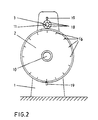
- the shaft 10 of the heating roller 2 and the shaft 11 of the pressure roller 3 are mounted in the stands 1 of the calender.
- a DC motor 12 drives the shaft 10 of the heating roller 2 and a DC motor 13 drives the shaft 11 of the pressure roller 3.
- the shaft 11 of the pressure roller 3 is slidably mounted in the calender stand 1, by means of a force generated by the hydraulic pressing device 24, the shaft 11 is pressed in the direction of the shaft 10.
- the location of the shaft 11 is dependent on the thickness of the sealing plate 14 built up on the heating roller 2.
- the position of the shaft 11 of the pressure roller 3 is determined by an encoder 15.
- the heating roller 2 is provided on its circumference with marks 16 arranged at the same distance.
- a sensor 17 is provided, each of which passes when one passes Mark 16 emits a pulse which is fed to the input 5 of the processor 9.
- marks 18 are attached to the pressure roller 3, the passage of which is sensed by an encoder 19 which is connected to the input 4 of the processor 9.
- the third input 6 of the processor 9 is connected to the encoder 15.
- the processor has two outputs 7 and 8, of which one output 7 is connected to the control device 20 for the motor 13 and the other output 8 to the control device 21 for the motor 12.
- Pipes 26 lead from the heating device 25 into the heating roller 2.
- a temperature sensor 27 is arranged in these pipes, the output signals of which are introduced into the input 28 of the processor 9.
- the pressure roller 3 is connected to the cooling device 30 via pipes 29.
- a temperature sensor 31 arranged in the tubes 29 is connected to the input 32 of the processor 9. From the output 33 a control line leads to the heating device 25, from the output 34 of the processor 9 a control line leads to the cooling device 30.
- Another output 35 of the processor 9 leads to the control device 36 of the hydraulic pressing device 24 on the pressure roller 3. From the output 37 of the processor 9, a control line leads to the control device 38 of the counter-bending device 39.
- a loading device 40 is arranged, which is connected to the output 41 of the processor 9.
- a device for the solvent supply 42 is provided, the solvent flow of which is controlled by the control device 43, which is connected to the output 44 of the processor. Furthermore, a material distribution device 45 is provided, the control of which is connected to the output 46 of the processor.
- Various memories 47 in which recipes and / or procedures are recorded, are connected to the input 49 of the processor 9 via the selection device 48.
- the output 50 of the processor which leads to the memory 47, is provided for the recording of programs according to a manually performed control.
Landscapes
- Engineering & Computer Science (AREA)
- Mechanical Engineering (AREA)
- Casting Or Compression Moulding Of Plastics Or The Like (AREA)
Applications Claiming Priority (2)
| Application Number | Priority Date | Filing Date | Title |
|---|---|---|---|
| DE4011426 | 1990-04-09 | ||
| DE4011426 | 1990-04-09 |
Publications (3)
| Publication Number | Publication Date |
|---|---|
| EP0451495A2 true EP0451495A2 (fr) | 1991-10-16 |
| EP0451495A3 EP0451495A3 (en) | 1992-03-11 |
| EP0451495B1 EP0451495B1 (fr) | 1994-11-17 |
Family
ID=6404054
Family Applications (1)
| Application Number | Title | Priority Date | Filing Date |
|---|---|---|---|
| EP91103202A Expired - Lifetime EP0451495B1 (fr) | 1990-04-09 | 1991-03-04 | Dispositif de contrôle d'une calandre pour la fabrication de plaques d'étanchéité |
Country Status (2)
| Country | Link |
|---|---|
| EP (1) | EP0451495B1 (fr) |
| DE (1) | DE59103518D1 (fr) |
Cited By (1)
| Publication number | Priority date | Publication date | Assignee | Title |
|---|---|---|---|---|
| EP0578036A1 (fr) * | 1992-07-07 | 1994-01-12 | Paul Troester Maschinenfabrik | Calandre et procédé pour produire des plaques d'étanchéité |
Families Citing this family (1)
| Publication number | Priority date | Publication date | Assignee | Title |
|---|---|---|---|---|
| CN106313402A (zh) * | 2016-07-28 | 2017-01-11 | 江苏锦竹工业用布有限公司 | 一种尼龙帘子布压延工序的控制装置 |
Family Cites Families (4)
| Publication number | Priority date | Publication date | Assignee | Title |
|---|---|---|---|---|
| BE625193A (fr) * | 1962-01-19 | |||
| FR1376499A (fr) * | 1963-03-19 | 1964-10-31 | Perfectionnements au serrage des cylindres de broyeuses et autres machines à cylindres | |
| JPS58141807A (ja) * | 1982-02-15 | 1983-08-23 | Mitsubishi Electric Corp | 自動板厚制御装置 |
| US4810179A (en) * | 1988-01-27 | 1989-03-07 | Marshall & Williams Company | Force indicator for casting machines |
-
1991
- 1991-03-04 EP EP91103202A patent/EP0451495B1/fr not_active Expired - Lifetime
- 1991-03-04 DE DE59103518T patent/DE59103518D1/de not_active Expired - Fee Related
Cited By (1)
| Publication number | Priority date | Publication date | Assignee | Title |
|---|---|---|---|---|
| EP0578036A1 (fr) * | 1992-07-07 | 1994-01-12 | Paul Troester Maschinenfabrik | Calandre et procédé pour produire des plaques d'étanchéité |
Also Published As
| Publication number | Publication date |
|---|---|
| DE59103518D1 (de) | 1994-12-22 |
| EP0451495B1 (fr) | 1994-11-17 |
| EP0451495A3 (en) | 1992-03-11 |
Similar Documents
| Publication | Publication Date | Title |
|---|---|---|
| DE3730043C2 (fr) | ||
| DE4034144C2 (de) | Strangpreßwalz-Vorrichtung und Verfahren zu deren Betrieb | |
| DE2950003C2 (de) | Verfahren zur Regelung der Foliendicke an einer Blasfolien-Extruderanlage | |
| DE10135345B4 (de) | Elektrische Spritzgussmaschine und Verfahren zum Steuern einer elektrischen Spritzgussmaschine | |
| DE2751225A1 (de) | Anordnung einer schmelzindex-messeinrichtung hinter dem siebpaket eines kunststoff-extruders und verfahren zum regeln der viskositaet von aufgeschmolzenem und auszuformendem kunststoff | |
| EP0268199B1 (fr) | Procédé de fabrication de pièces moulées à base de polymères et équipement pour l'exécution | |
| DE2704241A1 (de) | Verfahren und vorrichtung zum erzeugen eines gleichmaessigen, kontinuierlichen faserverbandes | |
| DE3153304C2 (fr) | ||
| EP0733457B1 (fr) | Extrudeuse à plusieurs composants | |
| DE69905521T2 (de) | Verfahren und Vorrichtung zum Herstellen von Garn aus themoplastischem geschnittenen Material | |
| DE102014117241A1 (de) | Verfahren zum optimierten Verstrecken von zumindest einem Faserband in einer Textilmaschine sowie Textilmaschine | |
| EP0451494B1 (fr) | Calandre pour la fabrication de plaques d'étanchéité | |
| DE4108992C2 (de) | Einrichtung und Verfahren zur Bestimmung von Formteilen für Spritzgußmaschinen | |
| EP0128421A2 (fr) | Procédé et dispositif pour la vulcanisation des pneumatiques | |
| DE102016123631A1 (de) | Vorrichtung und Verfahren zur Erzeugung von dreidimensionalen Objekten sowie dreidimensionales Objekt | |
| EP0451495A2 (fr) | Dispositif de contrôle d'une calandre pour la fabrication de plaques d'étanchéité | |
| DE4111220C2 (de) | Vorrichtung zur Steuerung eines Kalanders für die Herstellung von Dichtungsplatten | |
| DE102007012199A1 (de) | Verfahren zum Betreiben einer Plastifizierungseinrichtung, z. B. eines Extruders oder einer Spritzgussmaschine | |
| EP0452652B1 (fr) | Procédé et appareil pour produire une plaque d'étanchéité sur une calandre | |
| DE2940152A1 (de) | Verfahren und vorrichtung zum regeln des plastifizierens eines harzes in einer reihenschnecken-spritzgussmaschine | |
| DE9004098U1 (de) | Vorrichtung zur Steuerung eines Kalanders für die Herstellung von Dichtungsplatten | |
| DE1704537C3 (de) | Verfahren und Vorrichtung zum Herstellen von Tafeln, Folien o.dgl. aus verstärrktem Harz mit einer gleichmäßig dünnen Harzschutzshcicht auf jeder Oberfläche | |
| EP2616221A1 (fr) | Dispositif de production directe de smc | |
| EP0594018A1 (fr) | Appareil d'extrusion de profilés plastiques | |
| DE102022116096B4 (de) | Verfahren und Vorrichtung zur Schmelzimprägnierung von Fasern mit thermoplastischer Matrix |
Legal Events
| Date | Code | Title | Description |
|---|---|---|---|
| PUAI | Public reference made under article 153(3) epc to a published international application that has entered the european phase |
Free format text: ORIGINAL CODE: 0009012 |
|
| AK | Designated contracting states |
Kind code of ref document: A2 Designated state(s): DE FR GB IT |
|
| PUAL | Search report despatched |
Free format text: ORIGINAL CODE: 0009013 |
|
| AK | Designated contracting states |
Kind code of ref document: A3 Designated state(s): DE FR GB IT |
|
| 17P | Request for examination filed |
Effective date: 19920320 |
|
| 17Q | First examination report despatched |
Effective date: 19931012 |
|
| RAP1 | Party data changed (applicant data changed or rights of an application transferred) |
Owner name: PAUL TROESTER MASCHINENFABRIK |
|
| GRAA | (expected) grant |
Free format text: ORIGINAL CODE: 0009210 |
|
| ITF | It: translation for a ep patent filed | ||
| AK | Designated contracting states |
Kind code of ref document: B1 Designated state(s): DE FR GB IT |
|
| GBT | Gb: translation of ep patent filed (gb section 77(6)(a)/1977) |
Effective date: 19941117 |
|
| REF | Corresponds to: |
Ref document number: 59103518 Country of ref document: DE Date of ref document: 19941222 |
|
| ET | Fr: translation filed | ||
| PLBE | No opposition filed within time limit |
Free format text: ORIGINAL CODE: 0009261 |
|
| STAA | Information on the status of an ep patent application or granted ep patent |
Free format text: STATUS: NO OPPOSITION FILED WITHIN TIME LIMIT |
|
| 26N | No opposition filed | ||
| PGFP | Annual fee paid to national office [announced via postgrant information from national office to epo] |
Ref country code: GB Payment date: 19990224 Year of fee payment: 9 |
|
| PGFP | Annual fee paid to national office [announced via postgrant information from national office to epo] |
Ref country code: FR Payment date: 19990225 Year of fee payment: 9 |
|
| PGFP | Annual fee paid to national office [announced via postgrant information from national office to epo] |
Ref country code: DE Payment date: 19990301 Year of fee payment: 9 |
|
| PG25 | Lapsed in a contracting state [announced via postgrant information from national office to epo] |
Ref country code: GB Free format text: LAPSE BECAUSE OF NON-PAYMENT OF DUE FEES Effective date: 20000304 |
|
| GBPC | Gb: european patent ceased through non-payment of renewal fee |
Effective date: 20000304 |
|
| PG25 | Lapsed in a contracting state [announced via postgrant information from national office to epo] |
Ref country code: FR Free format text: LAPSE BECAUSE OF NON-PAYMENT OF DUE FEES Effective date: 20001130 |
|
| REG | Reference to a national code |
Ref country code: FR Ref legal event code: ST |
|
| PG25 | Lapsed in a contracting state [announced via postgrant information from national office to epo] |
Ref country code: DE Free format text: LAPSE BECAUSE OF NON-PAYMENT OF DUE FEES Effective date: 20010103 |
|
| PG25 | Lapsed in a contracting state [announced via postgrant information from national office to epo] |
Ref country code: IT Free format text: LAPSE BECAUSE OF NON-PAYMENT OF DUE FEES;WARNING: LAPSES OF ITALIAN PATENTS WITH EFFECTIVE DATE BEFORE 2007 MAY HAVE OCCURRED AT ANY TIME BEFORE 2007. THE CORRECT EFFECTIVE DATE MAY BE DIFFERENT FROM THE ONE RECORDED. Effective date: 20050304 |