EP0451505A1 - Système de mesure de la position incrémentiel - Google Patents
Système de mesure de la position incrémentiel Download PDFInfo
- Publication number
- EP0451505A1 EP0451505A1 EP91103460A EP91103460A EP0451505A1 EP 0451505 A1 EP0451505 A1 EP 0451505A1 EP 91103460 A EP91103460 A EP 91103460A EP 91103460 A EP91103460 A EP 91103460A EP 0451505 A1 EP0451505 A1 EP 0451505A1
- Authority
- EP
- European Patent Office
- Prior art keywords
- counter
- measuring system
- signals
- position measuring
- incremental position
- Prior art date
- Legal status (The legal status is an assumption and is not a legal conclusion. Google has not performed a legal analysis and makes no representation as to the accuracy of the status listed.)
- Granted
Links
- 238000011156 evaluation Methods 0.000 claims description 21
- 238000012806 monitoring device Methods 0.000 claims description 13
- 230000000737 periodic effect Effects 0.000 claims description 3
- 230000003213 activating effect Effects 0.000 claims description 2
- 238000000034 method Methods 0.000 claims description 2
- 238000001514 detection method Methods 0.000 claims 2
- 230000015572 biosynthetic process Effects 0.000 claims 1
- 239000003990 capacitor Substances 0.000 description 1
- 230000001419 dependent effect Effects 0.000 description 1
- 238000011161 development Methods 0.000 description 1
- 230000018109 developmental process Effects 0.000 description 1
- 238000010586 diagram Methods 0.000 description 1
- 238000005259 measurement Methods 0.000 description 1
- 210000002023 somite Anatomy 0.000 description 1
Images
Classifications
-
- G—PHYSICS
- G01—MEASURING; TESTING
- G01D—MEASURING NOT SPECIALLY ADAPTED FOR A SPECIFIC VARIABLE; ARRANGEMENTS FOR MEASURING TWO OR MORE VARIABLES NOT COVERED IN A SINGLE OTHER SUBCLASS; TARIFF METERING APPARATUS; MEASURING OR TESTING NOT OTHERWISE PROVIDED FOR
- G01D5/00—Mechanical means for transferring the output of a sensing member; Means for converting the output of a sensing member to another variable where the form or nature of the sensing member does not constrain the means for converting; Transducers not specially adapted for a specific variable
- G01D5/12—Mechanical means for transferring the output of a sensing member; Means for converting the output of a sensing member to another variable where the form or nature of the sensing member does not constrain the means for converting; Transducers not specially adapted for a specific variable using electric or magnetic means
- G01D5/244—Mechanical means for transferring the output of a sensing member; Means for converting the output of a sensing member to another variable where the form or nature of the sensing member does not constrain the means for converting; Transducers not specially adapted for a specific variable using electric or magnetic means influencing characteristics of pulses or pulse trains; generating pulses or pulse trains
- G01D5/245—Mechanical means for transferring the output of a sensing member; Means for converting the output of a sensing member to another variable where the form or nature of the sensing member does not constrain the means for converting; Transducers not specially adapted for a specific variable using electric or magnetic means influencing characteristics of pulses or pulse trains; generating pulses or pulse trains using a variable number of pulses in a train
- G01D5/2451—Incremental encoders
Definitions
- the invention relates to an incremental position measuring system according to the preamble of claim 1.
- Such position measuring systems are used in particular in numerical controls for measuring the relative position of a tool with respect to a workpiece to be machined, and in coordinate measuring machines.
- a grid-like incremental measuring graduation is scanned with a scanning device and periodic analog signals are generated. Square-wave signals are formed from the periodic analog signals and are fed to an up / down counter. The counter reading indicates the relative position of the objects to be measured. If the power supply fails, the meter reading and thus the knowledge of the current one Relative position lost.
- a reference mark must be approached, the absolute position of which is known. When this reference mark is passed, the up / down counter is set to a predetermined value and the measurement must be started again.
- the invention has for its object to provide an incremental position measuring system so that it works in a fail-safe and energy-saving manner and can quickly output the absolute relative position between the objects to be measured after a failure of the main power supply.
- the advantages achieved by the invention are, in particular, that after a failure of the main power supply, the relative position is present again exactly and can be passed on to an external unit by simple means.
- the interface of the external unit can therefore be simple.
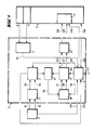
- the scanner 1 is two Analog scanning signals S1, S2 which are phase-shifted from one another by 90 ° to an evaluation device 2.
- counting signals S3, S4 are formed in a direction discriminator 3 from the two phase-shifted analog scanning signals S1, S2.
- the evaluation device 2 also contains an absolute value counter 4, to which the count signals S3, S4 are continuously fed.
- This absolute value counter 4, the direction discriminator 3 and the scanning device 1 are continuously supplied with current; this power supply can be operated, for example, in a particularly economical manner.
- the current power supply guarantees that the counter reading of the absolute value counter 4 always corresponds to the current relative position and can be output if required.
- the power supply consists of a main power supply 5 and an emergency power supply 6. Both power supplies 5 and 6 are connected to a monitoring device 7. This monitoring device 7 continuously checks the voltage level of the main power supply 5, as soon as the voltage level falls below a predetermined value, the main power supply 5 switches over to the emergency power supply 6.
- the main power supply 5 is integrated, for example, in a numerical control 8 and the emergency power supply 6 can be a battery or a storage capacitor.
- the emergency power supply 6 is also included in the numerical control 8 in the example shown.
- Normal operation means that the main power supply 5 is in operation and has a voltage level above the predetermined value.
- the monitoring device 7 detects normal operation and supplies a display signal S5 to a control logic 9.
- the control logic 9 activates a pulse generator 10 via the control signal S6, which outputs direction-dependent counting signals S7, S8 to a follow-up counter 11 as a function of the count of the absolute value counter 4.
- the counter values of the absolute value counter 4 and the follow-up counter 11 are continuously compared with one another by means of a comparator 12 and the comparator 12 causes the pulse generator 10 to deliver counter signals S7, S8 in the form of up or down counting pulses to the follow-up counter 11 by means of the control signal S9 until both meter readings are the same.
- the follow-up counter 11 is followed by a device 13 which, depending on the supplied count signals S7, S8, converts the output signals S10, S11 of the follow-up counter into two square-wave signals S12, S13 which are 90 ° out of phase with one another.
- These square-wave signals S12, S13 are present at the output of the evaluation device 2 and in the example shown are fed to the numerical control 8 and counted in an external counter 14 depending on the direction.
- the device 13 can also be arranged downstream of the pulse generator 10 and, from the count signals S7, S8, two phase-shifted by 90 ° relative to one another Form square wave signals S12, S13.
- the absolute value counter 4 sends a zero signal S21 to the control logic 9 and, if a reference signal S18 occurs at the same time, a zero pulse S15 is sent from the evaluation device 2 to the counter 14, which is then set to a predetermined value.
- Emergency operation means that the voltage level of the main power supply 5 has fallen below a predetermined value.
- the scanning device 1, the direction discriminator 3, the absolute value counter 4, the monitoring device 7 and the control logic 9 are supplied with current.
- the monitoring device 7 supplies a display signal S5 to the control logic 9, which deactivates the pulse generator 10 via the control signal S6.
- the display signal S5 can also be led directly to the pulse generator 10 and put it out of operation.
- the absolute zero position can be assigned to any reference mark.
- the absolute value counter 4 and the lag counter 11 are set to zero by means of the reset signal S16.
- the selection of the reference mark can in that a reference signal S17 is present at the control logic 9 and is logically AND-linked with the reference signal S18.
- the reference signal S17 is preferably generated by probing a reference edge.
- the reset signal S16 is therefore only output if the reference signal S17 and the reference signal S18 are present at the control logic 9 at the same time.
- the counter 14 of the numerical control 8 is set to a specific value when the absolute zero position is set or when it is detected, which value is preferably also zero. However, the value can also deviate from zero if the absolute zero position of the numerical control 8 does not match the absolute zero position of the position measuring system.
- the reference mark is defined as an absolute zero position after a certain number of revolutions when the reference signal S17 occurs.
- the absolute value counter 4 preferably consists of two counters.
- a counter for detecting the revolutions and a counter for detecting the position within one revolution are provided.
- the number of reference marks can be recorded with the first counter and the position between the reference marks with the second counter.
- the operating mode of the Monitoring device 7 to control logic 9 is reported.
- the control logic 9 and thus the evaluation device 2 sends a readiness signal S19 to the numerical control 8.
- the numerical control 8 or the counter 14 likewise reports to the evaluation device 2 with the ready signal S20 when there is readiness to receive the phase-shifted square-wave signals S12, S13. It is particularly advantageous if the system is only switched to normal operation when the standby signals S19 and S20 are present, and both standby signals S19 and S20 can be present on a signal line. This signal line is thus operated bidirectionally, for example by means of an open collector circuit.
Landscapes
- Physics & Mathematics (AREA)
- General Physics & Mathematics (AREA)
- Transmission And Conversion Of Sensor Element Output (AREA)
- Length Measuring Devices With Unspecified Measuring Means (AREA)
Priority Applications (1)
| Application Number | Priority Date | Filing Date | Title |
|---|---|---|---|
| AT9191103460T ATE105404T1 (de) | 1990-04-09 | 1991-03-07 | Inkrementales positions-messsystem. |
Applications Claiming Priority (2)
| Application Number | Priority Date | Filing Date | Title |
|---|---|---|---|
| DE4011411A DE4011411C2 (de) | 1990-04-09 | 1990-04-09 | Inkrementales Positionsmeßsystem |
| DE4011411 | 1990-04-09 |
Publications (2)
| Publication Number | Publication Date |
|---|---|
| EP0451505A1 true EP0451505A1 (fr) | 1991-10-16 |
| EP0451505B1 EP0451505B1 (fr) | 1994-05-04 |
Family
ID=6404045
Family Applications (1)
| Application Number | Title | Priority Date | Filing Date |
|---|---|---|---|
| EP91103460A Expired - Lifetime EP0451505B1 (fr) | 1990-04-09 | 1991-03-07 | Système de mesure de la position incrémentiel |
Country Status (5)
| Country | Link |
|---|---|
| US (1) | US5131017A (fr) |
| EP (1) | EP0451505B1 (fr) |
| JP (1) | JP2648740B2 (fr) |
| AT (1) | ATE105404T1 (fr) |
| DE (2) | DE4011411C2 (fr) |
Cited By (2)
| Publication number | Priority date | Publication date | Assignee | Title |
|---|---|---|---|---|
| GB2268273A (en) * | 1992-06-26 | 1994-01-05 | Mitutoyo Corp | A capacitance-type measuring device |
| FR2703450A1 (fr) * | 1993-03-31 | 1994-10-07 | Aut Comp | Codeur numérique incrémental absolu, installation et machine comportant ce codeur. |
Families Citing this family (8)
| Publication number | Priority date | Publication date | Assignee | Title |
|---|---|---|---|---|
| EP1610096B2 (fr) | 1997-04-16 | 2012-09-05 | Dr. Johannes Heidenhain GmbH | Dispositif de mesure de position et procédé de fonctionnement d'un dispositif de mesure de position |
| EP0880013B1 (fr) * | 1997-05-21 | 2003-04-09 | Robert Bosch Gmbh | Procédé de fonctionnement pour un capteur de position |
| DE19806099A1 (de) * | 1997-05-21 | 1998-11-26 | Bosch Gmbh Robert | Verfahren zum Betreiben eines Lagesensors |
| WO1999042790A1 (fr) * | 1998-02-21 | 1999-08-26 | Dr. Johannes Heidenhain Gmbh | Procede permettant de faire fonctionner un systeme de mesure de position et systeme de mesure de position approprie |
| US6181423B1 (en) | 1998-10-06 | 2001-01-30 | Jorge Uriarte | Linear encoder providing engagement by engraving |
| DE10055996A1 (de) * | 2000-11-11 | 2002-05-23 | Heidenhain Gmbh Dr Johannes | Positionsmessgerät und Verfahren zur Inbetriebnahme eines Positionsmessgerätes |
| DE10117194B4 (de) | 2001-04-05 | 2013-09-19 | Anton Rodi | Winkel- oder Wegmessgeber |
| ES2656388T3 (es) * | 2015-07-27 | 2018-02-27 | Dr. Johannes Heidenhain Gmbh | Dispositivo de medición de posición y procedimiento para su funcionamiento |
Citations (2)
| Publication number | Priority date | Publication date | Assignee | Title |
|---|---|---|---|---|
| DE2747208A1 (de) * | 1977-08-12 | 1979-02-15 | Rieder | Messeinrichtung, insbesondere laengenmesseinrichtung an werkzeugmaschinen o.dgl. |
| DE2732909B2 (de) * | 1977-07-21 | 1979-03-15 | Dr. Johannes Heidenhain Gmbh, 8225 Traunreut | Inkrementales LagemeBsystem |
Family Cites Families (13)
| Publication number | Priority date | Publication date | Assignee | Title |
|---|---|---|---|---|
| JPS5199418A (en) * | 1975-02-27 | 1976-09-02 | Laurel Bank Machine Co | Teidenjino ic memoriihojikairo |
| US4064501A (en) * | 1975-08-28 | 1977-12-20 | Unitrol, Inc. | Control system |
| US4224506A (en) * | 1978-03-24 | 1980-09-23 | Pitney Bowes Inc. | Electronic counter with non-volatile memory |
| AT373690B (de) * | 1980-06-11 | 1984-02-10 | Rieder Heinz | Messgeraet, indsbesondere laengen- oder winkelmessgeraet |
| JPS6148303U (fr) * | 1984-09-04 | 1986-04-01 | ||
| JPS61120903A (ja) * | 1984-11-19 | 1986-06-09 | Sumitomo Electric Ind Ltd | 角度検出回路 |
| JPS61154316A (ja) * | 1984-12-27 | 1986-07-14 | Toshiba Corp | 位置検出器 |
| JPS61184409A (ja) * | 1985-02-12 | 1986-08-18 | Amada Metoretsukusu:Kk | 移動体の位置検出装置 |
| DE3604160A1 (en) * | 1986-02-10 | 1987-09-10 | T & R Electronic Gmbh | Auxiliary device in connection with an electronic counter control device |
| JPS63187106A (ja) * | 1987-01-30 | 1988-08-02 | Mitsubishi Heavy Ind Ltd | 絶対位置検出器 |
| JPS63205507A (ja) * | 1987-02-21 | 1988-08-25 | Fanuc Ltd | アブソリユ−ト位置検出方式 |
| JPS6445590A (en) * | 1987-08-11 | 1989-02-20 | Kobe Steel Ltd | Absolute rotational angle detector for industrial robot |
| JPH01237415A (ja) * | 1988-03-17 | 1989-09-21 | Fuji Electric Co Ltd | エンコーダ監視装置 |
-
1990
- 1990-04-09 DE DE4011411A patent/DE4011411C2/de not_active Expired - Fee Related
-
1991
- 1991-03-07 DE DE59101535T patent/DE59101535D1/de not_active Expired - Fee Related
- 1991-03-07 EP EP91103460A patent/EP0451505B1/fr not_active Expired - Lifetime
- 1991-03-07 AT AT9191103460T patent/ATE105404T1/de not_active IP Right Cessation
- 1991-04-08 US US07/681,882 patent/US5131017A/en not_active Expired - Lifetime
- 1991-04-09 JP JP3076468A patent/JP2648740B2/ja not_active Expired - Fee Related
Patent Citations (2)
| Publication number | Priority date | Publication date | Assignee | Title |
|---|---|---|---|---|
| DE2732909B2 (de) * | 1977-07-21 | 1979-03-15 | Dr. Johannes Heidenhain Gmbh, 8225 Traunreut | Inkrementales LagemeBsystem |
| DE2747208A1 (de) * | 1977-08-12 | 1979-02-15 | Rieder | Messeinrichtung, insbesondere laengenmesseinrichtung an werkzeugmaschinen o.dgl. |
Cited By (3)
| Publication number | Priority date | Publication date | Assignee | Title |
|---|---|---|---|---|
| GB2268273A (en) * | 1992-06-26 | 1994-01-05 | Mitutoyo Corp | A capacitance-type measuring device |
| GB2268273B (en) * | 1992-06-26 | 1996-01-24 | Mitutoyo Corp | A capacitance-type measuring device |
| FR2703450A1 (fr) * | 1993-03-31 | 1994-10-07 | Aut Comp | Codeur numérique incrémental absolu, installation et machine comportant ce codeur. |
Also Published As
| Publication number | Publication date |
|---|---|
| DE4011411A1 (de) | 1991-10-10 |
| JP2648740B2 (ja) | 1997-09-03 |
| US5131017A (en) | 1992-07-14 |
| JPH04225110A (ja) | 1992-08-14 |
| ATE105404T1 (de) | 1994-05-15 |
| DE59101535D1 (de) | 1994-06-09 |
| EP0451505B1 (fr) | 1994-05-04 |
| DE4011411C2 (de) | 1993-09-30 |
Similar Documents
| Publication | Publication Date | Title |
|---|---|---|
| DE4342377B4 (de) | Anordnung und Verfahren zur seriellen Datenübertragung einer Positionsmeßeinrichtung | |
| EP1193472B1 (fr) | Procédé et appareil pour la détermination de la position absolue des capteurs de déplacements et d'angles | |
| DE2716775C2 (fr) | ||
| DE112013006990B4 (de) | Encoder und Servomotor | |
| EP1987316B1 (fr) | Surveillance fiable de la vitesse d'appareils de mesure de coordonnees | |
| DE4330823C2 (de) | Antriebsvorrichtung mit einer Sicherheitseinrichtung für den Sonderbetrieb | |
| DE3324333C2 (de) | Verfahren zur Überwachung eines elektronisch gesteuerten Schraubers | |
| DE2843810A1 (de) | Verfahren und einrichtung zur guetepruefung und ausschussanzeige beim anziehen von schraubverbindungen | |
| DE69012000T2 (de) | System zum Messen der absoluten Position eines Industrieroboters. | |
| EP0451505B1 (fr) | Système de mesure de la position incrémentiel | |
| DE3345724A1 (de) | Verfahren und anordnung zum erzeugen eines fehlerkompensierten positionsanzeigewertes | |
| EP0085161A2 (fr) | Dispositif digital électrique de mesure de longueurs ou d'angles | |
| WO1998001724A1 (fr) | Procede de determination de position et systeme de mesure pour la mise en oeuvre de ce procede | |
| EP1856485B1 (fr) | Procede bicanal de determination continue d'au moins un signal de sortie a partir de signaux d'entree variables | |
| EP0880013A1 (fr) | Procédé de fonctionnement pour un capteur de position | |
| DE2847779C3 (de) | Einrichtung zur Positionserfassung bei numerisch gesteuerten Werkzeugmaschinen | |
| EP2944592A1 (fr) | Procédé et dispositif d'inspection et de confection d'une bande de marchandise déroulante | |
| EP0066682B1 (fr) | Dispositif de positionnement | |
| DE3635305A1 (de) | Positionssteuergeraet | |
| EP2505965A2 (fr) | Procédé et unité de surveillance destinés à la vérification de valeurs de position | |
| DE2111635A1 (de) | Einrichtung zum Umsetzen der Phasenlage eines Signals in eine Folge von Impulsen | |
| EP3578295A1 (fr) | Dispositif de mesure de position et procédé de fonctionnement d'un dispositif de mesure de position | |
| DE3424246C2 (de) | Verfahren zur Überwachung eines Antriebssystems | |
| EP3035000B1 (fr) | Dispositif et procede de verification d'un signal de travail d'un dispositif de mesure de position | |
| DE3417016C1 (de) | Verfahren zur Ermittlung der Lage und Geschwindigkeit von Objekten |
Legal Events
| Date | Code | Title | Description |
|---|---|---|---|
| PUAI | Public reference made under article 153(3) epc to a published international application that has entered the european phase |
Free format text: ORIGINAL CODE: 0009012 |
|
| 17P | Request for examination filed |
Effective date: 19910319 |
|
| AK | Designated contracting states |
Kind code of ref document: A1 Designated state(s): AT CH DE FR GB IT LI |
|
| 17Q | First examination report despatched |
Effective date: 19930422 |
|
| ITF | It: translation for a ep patent filed | ||
| GRAA | (expected) grant |
Free format text: ORIGINAL CODE: 0009210 |
|
| AK | Designated contracting states |
Kind code of ref document: B1 Designated state(s): AT CH DE FR GB IT LI |
|
| REF | Corresponds to: |
Ref document number: 105404 Country of ref document: AT Date of ref document: 19940515 Kind code of ref document: T |
|
| ET | Fr: translation filed | ||
| REF | Corresponds to: |
Ref document number: 59101535 Country of ref document: DE Date of ref document: 19940609 |
|
| GBT | Gb: translation of ep patent filed (gb section 77(6)(a)/1977) |
Effective date: 19940517 |
|
| PLBE | No opposition filed within time limit |
Free format text: ORIGINAL CODE: 0009261 |
|
| STAA | Information on the status of an ep patent application or granted ep patent |
Free format text: STATUS: NO OPPOSITION FILED WITHIN TIME LIMIT |
|
| 26N | No opposition filed | ||
| PGFP | Annual fee paid to national office [announced via postgrant information from national office to epo] |
Ref country code: AT Payment date: 20010226 Year of fee payment: 11 |
|
| REG | Reference to a national code |
Ref country code: GB Ref legal event code: IF02 |
|
| PGFP | Annual fee paid to national office [announced via postgrant information from national office to epo] |
Ref country code: GB Payment date: 20020222 Year of fee payment: 12 |
|
| PGFP | Annual fee paid to national office [announced via postgrant information from national office to epo] |
Ref country code: CH Payment date: 20020225 Year of fee payment: 12 |
|
| PG25 | Lapsed in a contracting state [announced via postgrant information from national office to epo] |
Ref country code: AT Free format text: LAPSE BECAUSE OF NON-PAYMENT OF DUE FEES Effective date: 20020307 |
|
| PGFP | Annual fee paid to national office [announced via postgrant information from national office to epo] |
Ref country code: FR Payment date: 20020315 Year of fee payment: 12 |
|
| PG25 | Lapsed in a contracting state [announced via postgrant information from national office to epo] |
Ref country code: GB Free format text: LAPSE BECAUSE OF NON-PAYMENT OF DUE FEES Effective date: 20030307 |
|
| PG25 | Lapsed in a contracting state [announced via postgrant information from national office to epo] |
Ref country code: LI Free format text: LAPSE BECAUSE OF NON-PAYMENT OF DUE FEES Effective date: 20030331 Ref country code: CH Free format text: LAPSE BECAUSE OF NON-PAYMENT OF DUE FEES Effective date: 20030331 |
|
| GBPC | Gb: european patent ceased through non-payment of renewal fee |
Effective date: 20030307 |
|
| REG | Reference to a national code |
Ref country code: CH Ref legal event code: PL |
|
| PG25 | Lapsed in a contracting state [announced via postgrant information from national office to epo] |
Ref country code: FR Free format text: LAPSE BECAUSE OF NON-PAYMENT OF DUE FEES Effective date: 20031127 |
|
| REG | Reference to a national code |
Ref country code: FR Ref legal event code: ST |
|
| PG25 | Lapsed in a contracting state [announced via postgrant information from national office to epo] |
Ref country code: IT Free format text: LAPSE BECAUSE OF NON-PAYMENT OF DUE FEES;WARNING: LAPSES OF ITALIAN PATENTS WITH EFFECTIVE DATE BEFORE 2007 MAY HAVE OCCURRED AT ANY TIME BEFORE 2007. THE CORRECT EFFECTIVE DATE MAY BE DIFFERENT FROM THE ONE RECORDED. Effective date: 20050307 |
|
| PGFP | Annual fee paid to national office [announced via postgrant information from national office to epo] |
Ref country code: DE Payment date: 20060314 Year of fee payment: 16 |
|
| PG25 | Lapsed in a contracting state [announced via postgrant information from national office to epo] |
Ref country code: DE Free format text: LAPSE BECAUSE OF NON-PAYMENT OF DUE FEES Effective date: 20071002 |