EP0451717A1 - Table élévatrice pour surmonter une différence de niveau d'une voie de transport - Google Patents
Table élévatrice pour surmonter une différence de niveau d'une voie de transport Download PDFInfo
- Publication number
- EP0451717A1 EP0451717A1 EP91105391A EP91105391A EP0451717A1 EP 0451717 A1 EP0451717 A1 EP 0451717A1 EP 91105391 A EP91105391 A EP 91105391A EP 91105391 A EP91105391 A EP 91105391A EP 0451717 A1 EP0451717 A1 EP 0451717A1
- Authority
- EP
- European Patent Office
- Prior art keywords
- lifting
- frame
- table according
- lift table
- stand
- Prior art date
- Legal status (The legal status is an assumption and is not a legal conclusion. Google has not performed a legal analysis and makes no representation as to the accuracy of the status listed.)
- Granted
Links
- 230000003028 elevating effect Effects 0.000 title abstract 3
- 230000005540 biological transmission Effects 0.000 claims abstract description 17
- 239000011358 absorbing material Substances 0.000 claims description 4
- 230000005484 gravity Effects 0.000 claims description 4
- 230000033001 locomotion Effects 0.000 description 3
- 238000004519 manufacturing process Methods 0.000 description 3
- 239000000463 material Substances 0.000 description 3
- 230000000694 effects Effects 0.000 description 2
- 238000012423 maintenance Methods 0.000 description 2
- 230000003014 reinforcing effect Effects 0.000 description 2
- 230000000903 blocking effect Effects 0.000 description 1
- 239000004033 plastic Substances 0.000 description 1
- 230000002040 relaxant effect Effects 0.000 description 1
- 238000005096 rolling process Methods 0.000 description 1
Images




Classifications
-
- B—PERFORMING OPERATIONS; TRANSPORTING
- B65—CONVEYING; PACKING; STORING; HANDLING THIN OR FILAMENTARY MATERIAL
- B65G—TRANSPORT OR STORAGE DEVICES, e.g. CONVEYORS FOR LOADING OR TIPPING, SHOP CONVEYOR SYSTEMS OR PNEUMATIC TUBE CONVEYORS
- B65G41/00—Supporting frames or bases for conveyors as a whole, e.g. transportable conveyor frames
- B65G41/001—Supporting frames or bases for conveyors as a whole, e.g. transportable conveyor frames with the conveyor adjustably mounted on the supporting frame or base
- B65G41/003—Supporting frames or bases for conveyors as a whole, e.g. transportable conveyor frames with the conveyor adjustably mounted on the supporting frame or base mounted for linear movement only
Definitions
- the invention relates to a lifting table for overcoming a jump in height in conveyor lines for transport devices such as skids or the like according to the preamble of claim 1.
- crank pins are mounted eccentrically on shafts, the rotation of which causes the crank pins to perform a vertical stroke due to their eccentric mounting.
- a drive is provided which is connected to the drive via roller chains with gearwheels flanged onto the shafts. These roller chains lie within a frame designed as a stand.
- the invention has for its object to develop a lifting table according to the preamble of claim 1 such that the assembly and disassembly of endless power transmission means required for maintenance or repair work is as low as possible.
- the arrangement of the power transmission elements - seen in plan view of the lifting table - outside the stand frame enables the lifting drive to be easily exposed without extensive assembly or disassembly work being necessary. It is advantageous that the lifting frame only rests on the lifting members under the effect of gravity, so that it can be easily lifted off the lifting members if necessary.
- the force transmission elements seen in plan view of the lifting table — lie between the stand frame and the lifting frame.
- the lifting table is moved to its uppermost lifting position, wedged in this position and the lifting drive is moved back to the lowest position. Since the lifting sliders only lie against the lifting frame, they lift off the lifting frame when the lifting frame is wedged in a fixed manner, which creates a gap corresponding to the stroke between each lifting element and the lifting frame.
- the endless power transmission elements between the drive and the lifting arrangement can thus be removed axially without opening the power transmission elements themselves.
- the assembly and disassembly work for replacing the endless power transmission elements is therefore limited to a few simple steps, such as tensioning and relaxing after assembly or disassembly.
- the power transmission elements are located outside the lifting frame, as seen in a top view of the lifting table.
- the overall width is larger, but a movement and wedging of the lifting table is not necessary for the assembly or disassembly of the endless power transmission elements.
- drive belts preferably toothed belts
- noise values of significantly less than 70 dbA could be achieved.
- the stand frame - seen in plan view of the lifting table - advantageously lies within the lifting frame. If the belt drive is also outside the lifting frame, it may be appropriate to avoid excessive bearing loads on the drive shafts of the lifting arrangement if the longitudinal bar of the lifting frame adjacent to the belt drive crosses the crossbars of the stand frame.
- the lifting members are each provided as a lifting pin which is axially held in a lifting cheek and which, in order to achieve low operating noise, preferably bears against a track of the lifting frame with a roller.
- the lifting cheek that carries the crank pin can also be formed by the pulley on which the force transmission element rests.
- the lifting frame has box profiles as longitudinal beams which are open over their entire length on their mutually facing longitudinal sides, the transport rollers of the lifting frame mounted in the interior of the box profile being driven by endless belts which lie within the box profile.
- Flat belts or toothed belts are preferably used for this purpose. Due to the open long sides, only a small amount of assembly and disassembly is required to replace an endless belt. It is advantageously provided to provide the drive connections between adjacent transport rollers at changing end sections of the transport rollers in the manner of a sterndrive.
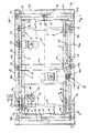
- a first frame 1 serves as a stand for the lifting table and has an essentially rectangular shape.
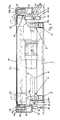
- the longitudinal beams 2 and 4 have a square cross-sectional profile (FIG. 3), while the cross beams 3 and 5 have a rectangular cross-sectional profile (FIG. 2).
- the height of the longitudinal and transverse beams is the same.
- the length of the longitudinal beams 2 and 4 corresponds approximately to twice the length of the transverse beams 3 and 5.
- a shaft 7 and 9 Adjacent to the crossbars 3 and 5 (FIGS. 1, 3) there is a shaft 7 and 9 at a distance a, respectively, which is held in its end sections in bearings 6 and 8 on the longitudinal beams 2 and 4.
- the two shafts 7 and 9 each have a lifting member on their end sections 7a, 7b and 9a, 9b, on which a lifting frame 18 rests under the effect of gravity.
- the lifting frame 18 is thus in four places, which ensures a high stability when lifting and lowering.
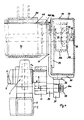
- a lifting cheek 11 which carries a crank pin 20 (FIG. 3), is rotatably arranged on one longitudinal side of the frame 1 on an end section 7a of the shaft 7 which projects laterally outward beyond the longitudinal beam 2.
- the axis 20a of the crank pin 20 lies at a distance e from the axis of rotation 17 of the shaft 7 (FIG. 4).
- the other end 7b of the shaft 7 carries a pulley 13 on its end section 7b, which projects laterally outwards beyond the other longitudinal beams 4 and in which a crank pin 20 is fastened axially.
- the axis 20a of the crank pin 20 lies at a distance e parallel to the axis of rotation 17 of the shaft 7 (FIG. 3).
- the belt 15 lies - in plan view according to FIG. 1 - approximately parallel to the longitudinal beam 4 outside the stand frame 1.
- an outer belt pulley 10b is arranged on the same drive shaft of the drive 10, on which lies a belt 16 which has a on the end 9b of the shaft 9 arranged pulley 14 loops.
- the belt 16 is also - in plan view according to FIG. 1 - approximately parallel to the longitudinal beam 4 outside the upright frame 1, but at a greater distance from the longitudinal beam than the belt 15.
- the belt drive 12 lying outside the stand frame 1 with the endless belts 15 and 16 is provided in such a way that all lifting members each have the same relative height to the stand 1.
- the stand frame 1 lies within the lifting frame; 1, the lifting frame 18 is thus larger than the stand frame 1.
- the lifting frame 18 is guided on the stand 1 so that it can move in height by means of guides 19.
- the guide 19 consists of a vertical U-profile 21, which is attached to the crossbar 3 or 5 of the stand frame 1 by an angle or the like.
- the opening of the U-profile 21 faces the crossbeam 23 or 25 of the lifting frame 18.
- a guide cam 26, which engages in the U-profile (FIG. 2), is fastened below the hollow profile of the crossbeams 23 and 25, which is rectangular in cross section.
- the lifting frame 18 is kept largely free of play in the longitudinal direction of the central longitudinal axis 27 of the lifting table and in the transverse direction. Tilting about the longitudinal central axis is prevented by the support of the longitudinal beams 22 and 24 of the lifting frame 18 on the crank pin 20.
- the belt drive 12 lies exactly between the stand frame 1 and the lifting frame 18 or between the longitudinal bar 4 of the stand frame 1 and the longitudinal bar 24 of the lifting frame 18.
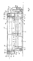
- the longitudinal beams 22 and 24 of the lifting frame 18 are formed from a box section 30 (FIGS. 3, 4), which is open via a longitudinal side 31; such a profile is also described as a C-profile.
- the box section 30 of the longitudinal beams 22 and 24 is fixed at its ends to the cross beams 23 and 25.
- the open long sides 31 of the box section 30 face each other, that is, on the inside of the lifting frame 18.
- transport rollers 40 and 41 are arranged within the lifting frame 18 transversely to the longitudinal center axis 27 of the lifting table.
- the transport rollers are held at their ends 42 in bearings 43 which are inside the box section 30 are fixed on the closed longitudinal side 32 of the profile (FIG. 4).
- the end sections 44 of the transport rollers 40 and 41 lying within the box section 30 each carry a pulley 45 to 45d.
- the belt pulley 45 is driven by a belt pulley 29 via a belt 46, preferably a toothed belt, which is fixed in a rotationally fixed manner on the shaft of a drive motor 28.
- the drive motor 28 is attached to the lifting frame 18 and is adjusted with it.
- the pulley 45a arranged on the other end section of the transport roller 40 carries a belt 46a which wraps around the pulley 45b of the adjacent transport roller 41.
- the pulley 45c arranged on the end section 44 on the other side of the middle transport roller 41 drives a belt 46b which drives the transport roller 40 adjacent to the other crossbar 25 via the pulley 45d.
- This type of drive of the transport rollers 40 and 41 via the drive motor 28 is referred to in technical circles as a Z drive.
- Timing belts are preferably used as belts. The drive of the transport rollers via belts ensures quiet operation.
- the transport rollers 40 and 41 are coated in their end regions via a ring section 50 with a friction-increasing plastic or rubber.
- the arrangement of a rubber sleeve formed from a corresponding material as a ring section 50 is also advantageous.
- the ring sections 50 stand as drive rollers for the transport device or the skid beyond a cover of the lifting frame, as in FIG. 2 is shown.
- the cover essentially consists of two cover plates 47, which rest and are fastened on support flanges 48 on the longitudinal beams 22 and 24 of the lifting frame.
- the support flanges 48 are firmly connected to the box section 30 on the inside of the box section above the opening in the longitudinal side 31, for example welded.
- the bearing surface 48a (FIG. 4) of a support flange 48 lies somewhat below the horizontal surface 49 of the box section 30.
- the outer jacket of the ring section 50 lies somewhat above this surface 49.
- angle plates 39 are welded to the crossbars (Fig. 2).
- the horizontal leg of the angle plates lies below the plane determined by the cover plates 47.
- the box section 30 is provided over a part of its length in the pivoting range of the crank pin 20 with a reinforcing angle section 35, which has a running surface 36 made of a suitable material for a roller 37 rotatably arranged on the crank pin 20 having.
- the tread 36 fastened to the angle profile 35 and the roller 37 are formed from a noise-absorbing material such as rubber, in order to ensure low noise when the parts move relative to one another.
- the roller 37 rotatably mounted on the crank pin 20 is axially secured by means of a nut 38.
- the shafts 7 and 9 are driven via the belts 15 and 16, so that the crank pins 20 which are arranged eccentrically to the shaft axes pivot the axis of rotation 17 of the shafts and perform a lifting movement.
- the rollers 37 roll on the raceways 36 of the reinforcing angle profiles 35 on the box profile 30.
- the maximum stroke of the lifting table is reached when the crank pins lie vertically above the axes of rotation 17 of the shafts 7 and 9.
- the stroke achieved corresponds to twice the eccentricity e that the crank pins 20 have about the axis of rotation 17 of the shafts 7 and 9.
- the lifting frame 18 is moved into its uppermost lifting position and blocked in this position. Thereafter, the drive 10 is set in motion again so that the crank pins lift off the lifting frame and a vertical gap is formed between the crank pins and the lifting frame, which corresponds approximately to twice the eccentricity e. Because of this gap, the belt 16 can now be lifted off the pulley 14 and removed axially without further dismantling work. The belt 15 can also be removed in the same way. After the axial placement and tensioning of new belts, the crank pins are moved back into contact with the lifting frame and the blocking of the lifting frame is removed. The lift table is ready for use again.
- the belts 46 to 46b of the sterndrive of the transport rollers 40 and 41 can also be replaced in a simple manner without great disassembly.
- the lift table is moved to its uppermost position so that the open long sides are exposed to the inside. Now the bearings of the transport rollers driven by the belt to be replaced are released and the transport rollers are inclined so that the belt can be axially removed from the pulley. Through the open Long side 31 makes it easy to remove and replace the belt without any further assembly or disassembly work.
- stiffening plates 34 can be inserted and screwed into the open long side 31 of the box section, which are supported against the two long edges in the open long side 31.
- a plurality of stiffening plates 34 can be arranged over the length of a longitudinal bar 22 or 24.
- limit switches 60 are shown in the upper left, which are actuated by cams 61 rotating with the shaft 9.
- the limit switches are used in the electrical control of the lifting table. It may be advantageous to provide the limit switches 60 and the cams 61 which actuate them - sitting on an extension of the shaft 9 - lying outside the lifting frame, as a result of which there is easier access for maintenance work.
- 5 to 8 corresponds in its basic structure to the lifting table according to FIGS. 1 to 4; the same reference numbers have therefore been used for the same parts.
- the belt drive 12 with the belts 15 and 16 in turn lies outside the stand frame 1 on the outside next to the longitudinal beam 4.
- the lifting frame 18 is - seen in plan view according to FIG. 1 - with its one longitudinal beam 22 on the outside next to the belt drive 12 facing longitudinal bar 2 of the stand frame, while the other longitudinal bar 24 of the lifting frame 18 - in plan view - inside next to the longitudinal bar 4th of the stand frame 1.
- the longitudinal beam 24 of the lifting frame crosses the cross beams 3 and 5 of the stand frame.
- the belt drive 12 is thus also outside the lifting frame 18.
- the belt drive 12 is therefore freely accessible in every position of the lifting frame 18 from outside the frames 1 and 18, so that the endless belts 15 and 16 axially from the pulleys 10a; 14 and 10; 13 can be removed without having to be separated.
- a housing 33 (FIGS. 1, 2).
- each lifting member is further formed by a cam disk 111, the jacket of which forms a guide track 112, on which the lifting frame 18 rests under the action of gravity.
- a stub shaft 120 is advantageously attached to the lifting frame 18 and carries a roller 37 rolling on the guide track 112 (FIG. 8), which is secured axially by the nut 38.
- the roller 37 has at least one tread made of noise-absorbing material such as rubber; the roller 37 itself is advantageously made of such a material.
- the shaft ends 120 protrude into the lifting frame 18; a stub shaft 120 of the one longitudinal beam 22 lies opposite the stub shaft 120 of the other longitudinal beam 24, such that two stub shafts each lie on a common axis.
- the cam disks 111 which are arranged on the end sections 7a, 7b and 9a, 9b of the shafts 7 and 9 in a rotationally fixed manner, are in a plan view of FIG Lift table - within the lifting frame 18.
- cam disks 111 which are fixed on the end sections 7a and 9a lie outside the stand frame 1 laterally next to the longitudinal beams 2, while the cam disks 111 which are fixed on the other end sections 7b and 9b lie - inranges - within the stand frame 1 lie on the side of the bearing 8 facing the bearing 6.
- the guide 19 between the lifting frame 18 and the stand frame 1 in turn consists of a U-profile 21 which is attached to the crossbar 23 or 25 on the crossbar 3 or 5 of the stand frame 1.
- the web of a T-profile 21a engages in the vertical guideway of the U-profile 21, which is fixed vertically on the crossbeam 23 or 25 of the lifting frame 18.
- the stand frame 1 In addition to the position of the lifting frame 18 and stand frame 1 shown in FIG. 1, it may be advantageous to arrange the stand frame 1 lying within the lifting frame 18.
- the shaft ends carrying the pulleys 13 and 14 must then protrude under the longitudinal beam 24 of the lifting frame so that the belt drive 12 lies outside the lifting frame.
Landscapes
- Engineering & Computer Science (AREA)
- Mechanical Engineering (AREA)
- Escalators And Moving Walkways (AREA)
- Accommodation For Nursing Or Treatment Tables (AREA)
- Auxiliary Methods And Devices For Loading And Unloading (AREA)
- Structure Of Belt Conveyors (AREA)
- Rollers For Roller Conveyors For Transfer (AREA)
Applications Claiming Priority (4)
| Application Number | Priority Date | Filing Date | Title |
|---|---|---|---|
| DE19904011318 DE4011318A1 (de) | 1990-04-07 | 1990-04-07 | Hubtisch zur ueberwindung eines hoehensprungs in foerderstrassen |
| DE4011318 | 1990-04-07 | ||
| DE4109631 | 1991-03-23 | ||
| DE19914109631 DE4109631B4 (de) | 1990-04-07 | 1991-03-23 | Hubtisch zur Überwindung eines Höhensprungs in Förderstraßen |
Publications (2)
| Publication Number | Publication Date |
|---|---|
| EP0451717A1 true EP0451717A1 (fr) | 1991-10-16 |
| EP0451717B1 EP0451717B1 (fr) | 1994-10-19 |
Family
ID=25891992
Family Applications (1)
| Application Number | Title | Priority Date | Filing Date |
|---|---|---|---|
| EP19910105391 Expired - Lifetime EP0451717B1 (fr) | 1990-04-07 | 1991-04-05 | Table élévatrice pour surmonter une différence de niveau d'une voie de transport |
Country Status (3)
| Country | Link |
|---|---|
| EP (1) | EP0451717B1 (fr) |
| DE (1) | DE4109631B4 (fr) |
| ES (1) | ES2064795T3 (fr) |
Cited By (7)
| Publication number | Priority date | Publication date | Assignee | Title |
|---|---|---|---|---|
| EP1428774A1 (fr) * | 2002-12-09 | 2004-06-16 | Siemens Aktiengesellschaft | Table élévatrice pour un dispositif de transport dans une voie de transport |
| AT500887A1 (de) * | 2002-10-19 | 2006-04-15 | Transnorm System Gmbh | Hubtisch |
| CN104495345A (zh) * | 2014-12-25 | 2015-04-08 | 江苏冠宇机械设备制造有限公司 | 提交出口移行机 |
| CN104528366A (zh) * | 2014-12-27 | 2015-04-22 | 江苏冠宇机械设备制造有限公司 | 用于汽车生产线的旋转装置 |
| CN104528308A (zh) * | 2014-12-26 | 2015-04-22 | 江苏冠宇机械设备制造有限公司 | 用于汽车生产线的移行装置 |
| CN107934866A (zh) * | 2017-12-07 | 2018-04-20 | 江苏汤辰机械装备制造股份有限公司 | 一种叠合楼板流水线翻转装置及方法 |
| US10315853B2 (en) | 2015-08-10 | 2019-06-11 | Superior Industries, Inc. | Conveyor leveling systems and methods |
Families Citing this family (2)
| Publication number | Priority date | Publication date | Assignee | Title |
|---|---|---|---|---|
| DE29700863U1 (de) * | 1997-01-20 | 1998-10-01 | Dennerlein GmbH, 28307 Bremen | Fördervorrichtung, insbesondere zum Ausschleusen und/oder Vereinzeln von Gütern |
| ES2273570B1 (es) * | 2005-04-15 | 2008-03-16 | Inveral, S.A. | Carro elevador hidraulico. |
Citations (2)
| Publication number | Priority date | Publication date | Assignee | Title |
|---|---|---|---|---|
| DE1127915B (de) * | 1959-08-26 | 1962-04-19 | George Merrill Martin | Bogenstapler |
| DE1903687U (de) * | 1964-07-29 | 1964-11-05 | Martini & Cie | Paletten-hebetisch. |
Family Cites Families (6)
| Publication number | Priority date | Publication date | Assignee | Title |
|---|---|---|---|---|
| FR1583428A (fr) * | 1968-03-01 | 1969-10-31 | Jesus Henri Leon Lucien | Dispositif transporteur a changement de direction |
| DE2108620A1 (de) * | 1971-02-24 | 1972-08-31 | Fritz Riedel Und Soehne | Mehrbahnige Material-Transportstraße mit halbautomatischer Quertransport-Einrichtung |
| DE3232764C2 (de) * | 1982-09-03 | 1985-03-07 | Mannesmann AG, 4000 Düsseldorf | Übergabestation für Fördergut |
| DE3445801A1 (de) * | 1984-12-15 | 1986-06-19 | Mato Maschinen- Und Metallwarenfabrik Curt Matthaei Gmbh & Co Kg, 6050 Offenbach | Ein- und ausschleusstation |
| DE3601699A1 (de) * | 1986-01-22 | 1987-07-23 | Bosch Gmbh Robert | Foerdereinrichtung zum transport von werkstuecken |
| DE8914111U1 (de) * | 1989-11-30 | 1990-01-18 | Wegoma GmbH Maschinenfabrik i.K., 75015 Bretten | Zuführvorrichtung für Profilstäbe von Fensterrahmen |
-
1991
- 1991-03-23 DE DE19914109631 patent/DE4109631B4/de not_active Expired - Lifetime
- 1991-04-05 EP EP19910105391 patent/EP0451717B1/fr not_active Expired - Lifetime
- 1991-04-05 ES ES91105391T patent/ES2064795T3/es not_active Expired - Lifetime
Patent Citations (2)
| Publication number | Priority date | Publication date | Assignee | Title |
|---|---|---|---|---|
| DE1127915B (de) * | 1959-08-26 | 1962-04-19 | George Merrill Martin | Bogenstapler |
| DE1903687U (de) * | 1964-07-29 | 1964-11-05 | Martini & Cie | Paletten-hebetisch. |
Cited By (9)
| Publication number | Priority date | Publication date | Assignee | Title |
|---|---|---|---|---|
| AT500887A1 (de) * | 2002-10-19 | 2006-04-15 | Transnorm System Gmbh | Hubtisch |
| AT500887B1 (de) * | 2002-10-19 | 2007-02-15 | Transnorm System Gmbh | Hubtisch |
| EP1428774A1 (fr) * | 2002-12-09 | 2004-06-16 | Siemens Aktiengesellschaft | Table élévatrice pour un dispositif de transport dans une voie de transport |
| CN104495345A (zh) * | 2014-12-25 | 2015-04-08 | 江苏冠宇机械设备制造有限公司 | 提交出口移行机 |
| CN104495345B (zh) * | 2014-12-25 | 2016-11-23 | 江苏冠宇机械设备制造有限公司 | 提交出口移行机 |
| CN104528308A (zh) * | 2014-12-26 | 2015-04-22 | 江苏冠宇机械设备制造有限公司 | 用于汽车生产线的移行装置 |
| CN104528366A (zh) * | 2014-12-27 | 2015-04-22 | 江苏冠宇机械设备制造有限公司 | 用于汽车生产线的旋转装置 |
| US10315853B2 (en) | 2015-08-10 | 2019-06-11 | Superior Industries, Inc. | Conveyor leveling systems and methods |
| CN107934866A (zh) * | 2017-12-07 | 2018-04-20 | 江苏汤辰机械装备制造股份有限公司 | 一种叠合楼板流水线翻转装置及方法 |
Also Published As
| Publication number | Publication date |
|---|---|
| ES2064795T3 (es) | 1995-02-01 |
| DE4109631B4 (de) | 2004-09-16 |
| DE4109631A1 (de) | 1992-09-24 |
| EP0451717B1 (fr) | 1994-10-19 |
Similar Documents
| Publication | Publication Date | Title |
|---|---|---|
| DE602004000785T2 (de) | Fördergerät mit Trägern | |
| EP0857679A2 (fr) | Dispositif d'enroulement d'une bande de matériau | |
| WO2012006650A1 (fr) | Dispositif convoyeur de transport | |
| EP0291775A2 (fr) | Appareil pour le traitement biaxial simultané de films | |
| DE3513381A1 (de) | Umlenk-verschiebe-modul fuer werkstuecke, werkstuecktraeger oder dergleichen | |
| DE1271369B (de) | Vorrichtung zum Abstellen von Kraftfahrzeugen od. dgl. | |
| DE68906387T2 (de) | Förderband. | |
| DE6903037U (de) | Abstellgeruest mit umlaufplattformen fuer fahrzeuge. | |
| EP0434862B1 (fr) | Dispositif de soulèvement, notamment pour convoyeurs | |
| EP0451717B1 (fr) | Table élévatrice pour surmonter une différence de niveau d'une voie de transport | |
| EP0353556A1 (fr) | Dispositif pour le stockage d'objets de grande longueur | |
| DE2506560A1 (de) | Angetriebener kettenfoerderer | |
| EP0008082B1 (fr) | Garage pour garer les véhicules l'un au-dessus de l'autre | |
| DE2722320C2 (de) | Förderer mit sich gegenseitig überlappenden Platten | |
| DE2458645A1 (de) | Personen-befoerderungsanlage | |
| DE4011318C2 (fr) | ||
| DE2018199C3 (de) | Vorrichtung zur kontinuierlichen Herstellung von mit flexiblen Folien kaschierten Hartschaumplatten insbesondere auf Polyurethanbasis | |
| EP0154290A2 (fr) | Garage en forme de roue | |
| EP1273549B1 (fr) | Dispositif de levage | |
| WO2004050420A1 (fr) | Vehicule d'aire de stationnement pourvu d'un dispositif d'entrainement a vis sans fin | |
| EP0704404B1 (fr) | Plate-forme de levage | |
| DE29700863U1 (de) | Fördervorrichtung, insbesondere zum Ausschleusen und/oder Vereinzeln von Gütern | |
| DE2918122A1 (de) | Walzgeruest | |
| DE1434753C (de) | Vorrichtung zum senkrechten und/ oder waagerechten und/oder geneigten Transport von Fahrzeugen, insbesondere in Garagen | |
| DE60100214T2 (de) | Schwenkstation für die Fördervorrichtung einer Behandlungsanlage |
Legal Events
| Date | Code | Title | Description |
|---|---|---|---|
| PUAI | Public reference made under article 153(3) epc to a published international application that has entered the european phase |
Free format text: ORIGINAL CODE: 0009012 |
|
| AK | Designated contracting states |
Kind code of ref document: A1 Designated state(s): BE ES FR GB IT LU NL SE |
|
| 17P | Request for examination filed |
Effective date: 19920331 |
|
| 17Q | First examination report despatched |
Effective date: 19930310 |
|
| RBV | Designated contracting states (corrected) |
Designated state(s): ES FR GB IT SE |
|
| GRAA | (expected) grant |
Free format text: ORIGINAL CODE: 0009210 |
|
| RAP1 | Party data changed (applicant data changed or rights of an application transferred) |
Owner name: STOTZ, KRAEMER GMBH MATERIALFLUSSYSTEME UND AUTOMA |
|
| AK | Designated contracting states |
Kind code of ref document: B1 Designated state(s): ES FR GB IT SE |
|
| ET | Fr: translation filed | ||
| ITF | It: translation for a ep patent filed | ||
| PG25 | Lapsed in a contracting state [announced via postgrant information from national office to epo] |
Ref country code: SE Effective date: 19950119 |
|
| REG | Reference to a national code |
Ref country code: ES Ref legal event code: FG2A Ref document number: 2064795 Country of ref document: ES Kind code of ref document: T3 |
|
| GBT | Gb: translation of ep patent filed (gb section 77(6)(a)/1977) |
Effective date: 19950124 |
|
| PLBE | No opposition filed within time limit |
Free format text: ORIGINAL CODE: 0009261 |
|
| STAA | Information on the status of an ep patent application or granted ep patent |
Free format text: STATUS: NO OPPOSITION FILED WITHIN TIME LIMIT |
|
| 26N | No opposition filed | ||
| REG | Reference to a national code |
Ref country code: GB Ref legal event code: IF02 |
|
| PGFP | Annual fee paid to national office [announced via postgrant information from national office to epo] |
Ref country code: ES Payment date: 20080429 Year of fee payment: 18 |
|
| PGFP | Annual fee paid to national office [announced via postgrant information from national office to epo] |
Ref country code: IT Payment date: 20080426 Year of fee payment: 18 |
|
| PGFP | Annual fee paid to national office [announced via postgrant information from national office to epo] |
Ref country code: FR Payment date: 20080412 Year of fee payment: 18 |
|
| PGFP | Annual fee paid to national office [announced via postgrant information from national office to epo] |
Ref country code: GB Payment date: 20080421 Year of fee payment: 18 |
|
| GBPC | Gb: european patent ceased through non-payment of renewal fee |
Effective date: 20090405 |
|
| REG | Reference to a national code |
Ref country code: FR Ref legal event code: ST Effective date: 20091231 |
|
| PG25 | Lapsed in a contracting state [announced via postgrant information from national office to epo] |
Ref country code: FR Free format text: LAPSE BECAUSE OF NON-PAYMENT OF DUE FEES Effective date: 20091222 Ref country code: GB Free format text: LAPSE BECAUSE OF NON-PAYMENT OF DUE FEES Effective date: 20090405 |
|
| REG | Reference to a national code |
Ref country code: ES Ref legal event code: FD2A Effective date: 20090406 |
|
| PG25 | Lapsed in a contracting state [announced via postgrant information from national office to epo] |
Ref country code: ES Free format text: LAPSE BECAUSE OF NON-PAYMENT OF DUE FEES Effective date: 20090406 |
|
| PG25 | Lapsed in a contracting state [announced via postgrant information from national office to epo] |
Ref country code: IT Free format text: LAPSE BECAUSE OF NON-PAYMENT OF DUE FEES Effective date: 20090405 |