EP0451950A1 - Verfahren zur Herstellung von supraleitendem Oxidmaterial durch Brennen und Vorrichtung dafür - Google Patents
Verfahren zur Herstellung von supraleitendem Oxidmaterial durch Brennen und Vorrichtung dafür Download PDFInfo
- Publication number
- EP0451950A1 EP0451950A1 EP91302012A EP91302012A EP0451950A1 EP 0451950 A1 EP0451950 A1 EP 0451950A1 EP 91302012 A EP91302012 A EP 91302012A EP 91302012 A EP91302012 A EP 91302012A EP 0451950 A1 EP0451950 A1 EP 0451950A1
- Authority
- EP
- European Patent Office
- Prior art keywords
- firing
- gas
- fired
- layer
- oxide superconductive
- Prior art date
- Legal status (The legal status is an assumption and is not a legal conclusion. Google has not performed a legal analysis and makes no representation as to the accuracy of the status listed.)
- Granted
Links
- 239000000463 material Substances 0.000 title claims abstract description 174
- 238000010304 firing Methods 0.000 title claims abstract description 144
- 238000000034 method Methods 0.000 title claims abstract description 32
- 239000000758 substrate Substances 0.000 claims abstract description 43
- 239000000843 powder Substances 0.000 claims abstract description 18
- 239000000919 ceramic Substances 0.000 claims abstract description 11
- 229910010272 inorganic material Inorganic materials 0.000 claims description 26
- 239000011147 inorganic material Substances 0.000 claims description 26
- 239000012298 atmosphere Substances 0.000 claims description 24
- 239000000203 mixture Substances 0.000 claims description 12
- 150000001875 compounds Chemical class 0.000 claims description 8
- 230000000694 effects Effects 0.000 claims description 6
- 229910015901 Bi-Sr-Ca-Cu-O Chemical class 0.000 claims description 3
- 229910009203 Y-Ba-Cu-O Inorganic materials 0.000 claims description 3
- 238000011144 upstream manufacturing Methods 0.000 claims description 3
- 239000002887 superconductor Substances 0.000 abstract description 2
- 239000007789 gas Substances 0.000 description 132
- QVGXLLKOCUKJST-UHFFFAOYSA-N atomic oxygen Chemical compound [O] QVGXLLKOCUKJST-UHFFFAOYSA-N 0.000 description 19
- 239000001301 oxygen Substances 0.000 description 19
- 229910052760 oxygen Inorganic materials 0.000 description 19
- MCMNRKCIXSYSNV-UHFFFAOYSA-N Zirconium dioxide Chemical compound O=[Zr]=O MCMNRKCIXSYSNV-UHFFFAOYSA-N 0.000 description 10
- 230000000052 comparative effect Effects 0.000 description 10
- 230000015572 biosynthetic process Effects 0.000 description 7
- 238000010438 heat treatment Methods 0.000 description 6
- 229910052751 metal Inorganic materials 0.000 description 6
- 239000002184 metal Substances 0.000 description 6
- PNEYBMLMFCGWSK-UHFFFAOYSA-N aluminium oxide Inorganic materials [O-2].[O-2].[O-2].[Al+3].[Al+3] PNEYBMLMFCGWSK-UHFFFAOYSA-N 0.000 description 5
- OKTJSMMVPCPJKN-UHFFFAOYSA-N Carbon Chemical compound [C] OKTJSMMVPCPJKN-UHFFFAOYSA-N 0.000 description 4
- 229910052799 carbon Inorganic materials 0.000 description 4
- KFZMGEQAYNKOFK-UHFFFAOYSA-N Isopropanol Chemical compound CC(C)O KFZMGEQAYNKOFK-UHFFFAOYSA-N 0.000 description 3
- 229910001026 inconel Inorganic materials 0.000 description 3
- 239000012784 inorganic fiber Substances 0.000 description 3
- 238000009434 installation Methods 0.000 description 3
- 238000005259 measurement Methods 0.000 description 3
- 238000005192 partition Methods 0.000 description 3
- 230000000630 rising effect Effects 0.000 description 3
- 229910001220 stainless steel Inorganic materials 0.000 description 3
- 239000010935 stainless steel Substances 0.000 description 3
- IJGRMHOSHXDMSA-UHFFFAOYSA-N Atomic nitrogen Chemical compound N#N IJGRMHOSHXDMSA-UHFFFAOYSA-N 0.000 description 2
- QPLDLSVMHZLSFG-UHFFFAOYSA-N Copper oxide Chemical compound [Cu]=O QPLDLSVMHZLSFG-UHFFFAOYSA-N 0.000 description 2
- CPLXHLVBOLITMK-UHFFFAOYSA-N Magnesium oxide Chemical compound [Mg]=O CPLXHLVBOLITMK-UHFFFAOYSA-N 0.000 description 2
- -1 SUS 430 Chemical class 0.000 description 2
- GWEVSGVZZGPLCZ-UHFFFAOYSA-N Titan oxide Chemical compound O=[Ti]=O GWEVSGVZZGPLCZ-UHFFFAOYSA-N 0.000 description 2
- 229910052797 bismuth Inorganic materials 0.000 description 2
- JCXGWMGPZLAOME-UHFFFAOYSA-N bismuth atom Chemical compound [Bi] JCXGWMGPZLAOME-UHFFFAOYSA-N 0.000 description 2
- WMWLMWRWZQELOS-UHFFFAOYSA-N bismuth(iii) oxide Chemical compound O=[Bi]O[Bi]=O WMWLMWRWZQELOS-UHFFFAOYSA-N 0.000 description 2
- 239000011449 brick Substances 0.000 description 2
- 239000013078 crystal Substances 0.000 description 2
- 238000002425 crystallisation Methods 0.000 description 2
- 230000008025 crystallization Effects 0.000 description 2
- 239000011521 glass Substances 0.000 description 2
- 229910001119 inconels 625 Inorganic materials 0.000 description 2
- 230000005389 magnetism Effects 0.000 description 2
- 230000003647 oxidation Effects 0.000 description 2
- 238000007254 oxidation reaction Methods 0.000 description 2
- 229910052761 rare earth metal Inorganic materials 0.000 description 2
- 239000007858 starting material Substances 0.000 description 2
- BVKZGUZCCUSVTD-UHFFFAOYSA-L Carbonate Chemical compound [O-]C([O-])=O BVKZGUZCCUSVTD-UHFFFAOYSA-L 0.000 description 1
- 229910002480 Cu-O Inorganic materials 0.000 description 1
- 229910052691 Erbium Inorganic materials 0.000 description 1
- 229910052693 Europium Inorganic materials 0.000 description 1
- 229910052688 Gadolinium Inorganic materials 0.000 description 1
- 229910052765 Lutetium Inorganic materials 0.000 description 1
- 229910000831 Steel Inorganic materials 0.000 description 1
- 229910052769 Ytterbium Inorganic materials 0.000 description 1
- 238000010521 absorption reaction Methods 0.000 description 1
- 239000000853 adhesive Substances 0.000 description 1
- 230000001070 adhesive effect Effects 0.000 description 1
- 238000000137 annealing Methods 0.000 description 1
- 239000011230 binding agent Substances 0.000 description 1
- 238000007664 blowing Methods 0.000 description 1
- 238000001816 cooling Methods 0.000 description 1
- 229910052593 corundum Inorganic materials 0.000 description 1
- 230000003247 decreasing effect Effects 0.000 description 1
- 238000003618 dip coating Methods 0.000 description 1
- 238000007606 doctor blade method Methods 0.000 description 1
- 229910052737 gold Inorganic materials 0.000 description 1
- 229910000856 hastalloy Inorganic materials 0.000 description 1
- 229910052747 lanthanoid Inorganic materials 0.000 description 1
- 150000002602 lanthanoids Chemical class 0.000 description 1
- 229910052746 lanthanum Inorganic materials 0.000 description 1
- 239000000395 magnesium oxide Substances 0.000 description 1
- 238000002595 magnetic resonance imaging Methods 0.000 description 1
- 238000004519 manufacturing process Methods 0.000 description 1
- 238000002844 melting Methods 0.000 description 1
- 230000008018 melting Effects 0.000 description 1
- 150000002739 metals Chemical class 0.000 description 1
- 229910052757 nitrogen Inorganic materials 0.000 description 1
- 239000012299 nitrogen atmosphere Substances 0.000 description 1
- 229910000510 noble metal Inorganic materials 0.000 description 1
- 239000002245 particle Substances 0.000 description 1
- 229910052697 platinum Inorganic materials 0.000 description 1
- 230000001681 protective effect Effects 0.000 description 1
- 229910052706 scandium Inorganic materials 0.000 description 1
- HBMJWWWQQXIZIP-UHFFFAOYSA-N silicon carbide Chemical compound [Si+]#[C-] HBMJWWWQQXIZIP-UHFFFAOYSA-N 0.000 description 1
- 229910010271 silicon carbide Inorganic materials 0.000 description 1
- 229910052709 silver Inorganic materials 0.000 description 1
- 239000002904 solvent Substances 0.000 description 1
- 239000007921 spray Substances 0.000 description 1
- 238000005507 spraying Methods 0.000 description 1
- 239000010959 steel Substances 0.000 description 1
- LEDMRZGFZIAGGB-UHFFFAOYSA-L strontium carbonate Chemical compound [Sr+2].[O-]C([O-])=O LEDMRZGFZIAGGB-UHFFFAOYSA-L 0.000 description 1
- 229910000018 strontium carbonate Inorganic materials 0.000 description 1
- 239000000126 substance Substances 0.000 description 1
- 229910001845 yogo sapphire Inorganic materials 0.000 description 1
- 229910052727 yttrium Inorganic materials 0.000 description 1
Images



Classifications
-
- C—CHEMISTRY; METALLURGY
- C04—CEMENTS; CONCRETE; ARTIFICIAL STONE; CERAMICS; REFRACTORIES
- C04B—LIME, MAGNESIA; SLAG; CEMENTS; COMPOSITIONS THEREOF, e.g. MORTARS, CONCRETE OR LIKE BUILDING MATERIALS; ARTIFICIAL STONE; CERAMICS; REFRACTORIES; TREATMENT OF NATURAL STONE
- C04B35/00—Shaped ceramic products characterised by their composition; Ceramics compositions; Processing powders of inorganic compounds preparatory to the manufacturing of ceramic products
- C04B35/01—Shaped ceramic products characterised by their composition; Ceramics compositions; Processing powders of inorganic compounds preparatory to the manufacturing of ceramic products based on oxide ceramics
- C04B35/45—Shaped ceramic products characterised by their composition; Ceramics compositions; Processing powders of inorganic compounds preparatory to the manufacturing of ceramic products based on oxide ceramics based on copper oxide or solid solutions thereof with other oxides
-
- C—CHEMISTRY; METALLURGY
- C04—CEMENTS; CONCRETE; ARTIFICIAL STONE; CERAMICS; REFRACTORIES
- C04B—LIME, MAGNESIA; SLAG; CEMENTS; COMPOSITIONS THEREOF, e.g. MORTARS, CONCRETE OR LIKE BUILDING MATERIALS; ARTIFICIAL STONE; CERAMICS; REFRACTORIES; TREATMENT OF NATURAL STONE
- C04B35/00—Shaped ceramic products characterised by their composition; Ceramics compositions; Processing powders of inorganic compounds preparatory to the manufacturing of ceramic products
- C04B35/01—Shaped ceramic products characterised by their composition; Ceramics compositions; Processing powders of inorganic compounds preparatory to the manufacturing of ceramic products based on oxide ceramics
- C04B35/45—Shaped ceramic products characterised by their composition; Ceramics compositions; Processing powders of inorganic compounds preparatory to the manufacturing of ceramic products based on oxide ceramics based on copper oxide or solid solutions thereof with other oxides
- C04B35/4504—Shaped ceramic products characterised by their composition; Ceramics compositions; Processing powders of inorganic compounds preparatory to the manufacturing of ceramic products based on oxide ceramics based on copper oxide or solid solutions thereof with other oxides containing rare earth oxides
-
- C—CHEMISTRY; METALLURGY
- C04—CEMENTS; CONCRETE; ARTIFICIAL STONE; CERAMICS; REFRACTORIES
- C04B—LIME, MAGNESIA; SLAG; CEMENTS; COMPOSITIONS THEREOF, e.g. MORTARS, CONCRETE OR LIKE BUILDING MATERIALS; ARTIFICIAL STONE; CERAMICS; REFRACTORIES; TREATMENT OF NATURAL STONE
- C04B35/00—Shaped ceramic products characterised by their composition; Ceramics compositions; Processing powders of inorganic compounds preparatory to the manufacturing of ceramic products
- C04B35/01—Shaped ceramic products characterised by their composition; Ceramics compositions; Processing powders of inorganic compounds preparatory to the manufacturing of ceramic products based on oxide ceramics
- C04B35/45—Shaped ceramic products characterised by their composition; Ceramics compositions; Processing powders of inorganic compounds preparatory to the manufacturing of ceramic products based on oxide ceramics based on copper oxide or solid solutions thereof with other oxides
- C04B35/4521—Shaped ceramic products characterised by their composition; Ceramics compositions; Processing powders of inorganic compounds preparatory to the manufacturing of ceramic products based on oxide ceramics based on copper oxide or solid solutions thereof with other oxides containing bismuth oxide
-
- F—MECHANICAL ENGINEERING; LIGHTING; HEATING; WEAPONS; BLASTING
- F27—FURNACES; KILNS; OVENS; RETORTS
- F27B—FURNACES, KILNS, OVENS OR RETORTS IN GENERAL; OPEN SINTERING OR LIKE APPARATUS
- F27B17/00—Furnaces of a kind not covered by any of groups F27B1/00 - F27B15/00
- F27B17/0016—Chamber type furnaces
- F27B17/0083—Chamber type furnaces with means for circulating the atmosphere
-
- H—ELECTRICITY
- H10—SEMICONDUCTOR DEVICES; ELECTRIC SOLID-STATE DEVICES NOT OTHERWISE PROVIDED FOR
- H10N—ELECTRIC SOLID-STATE DEVICES NOT OTHERWISE PROVIDED FOR
- H10N60/00—Superconducting devices
- H10N60/01—Manufacture or treatment
- H10N60/0268—Manufacture or treatment of devices comprising copper oxide
-
- Y—GENERAL TAGGING OF NEW TECHNOLOGICAL DEVELOPMENTS; GENERAL TAGGING OF CROSS-SECTIONAL TECHNOLOGIES SPANNING OVER SEVERAL SECTIONS OF THE IPC; TECHNICAL SUBJECTS COVERED BY FORMER USPC CROSS-REFERENCE ART COLLECTIONS [XRACs] AND DIGESTS
- Y10—TECHNICAL SUBJECTS COVERED BY FORMER USPC
- Y10S—TECHNICAL SUBJECTS COVERED BY FORMER USPC CROSS-REFERENCE ART COLLECTIONS [XRACs] AND DIGESTS
- Y10S505/00—Superconductor technology: apparatus, material, process
- Y10S505/725—Process of making or treating high tc, above 30 k, superconducting shaped material, article, or device
- Y10S505/742—Annealing
Definitions
- the present invention relates to a process for producing an oxide superconductive material by firing as well as to an apparatus therefor. More particularly, the present invention relates to a process for producing an oxide superconductive material by firing, which process can suitably carry out complete firing and oxidation of a ceramic superconductive powder, etc., as well as to an apparatus therefor.
- the present invention further relates to a process for producing a bottomed cylindrical oxide superconductive material by firing, in an atmosphere enabling uniform firing, a bottomed cylindrical material comprising at least two layers of (a) a bottomed cylindrical substrate layer and (b) a layer to become an oxide superconductive layer when fired, formed on the substrate layer (a).
- Oxide superconductive materials have drawn people's attention in recent years because they exhibit high critical temperatures, and their application in fields such as electric power, magnetic resonance imaging, magnetic shielding and the like are expected.
- magnetic shielding apparatuses in particular, use of a bottomed (one end-closed) cylindrical superconductive material is being tried for measurement of the very weak magnetism of living body.
- Cylindrical oxide superconductive materials can generally be obtained in an integral form of (a) a cylindrical substrate and (b) an oxide superconductive layer provided thereon, by forming, on a cylindrical substrate made of a metal or the like, a layer to become an oxide superconductive layer and then subjecting them to firing.
- An electric furnace is often used for the firing of a special ceramic which can be made at a high temperature and which must be made at a precisely controlled temperature.
- a firing apparatus As the firing furnace used for the above-mentioned purpose, there is known, for example, a firing apparatus [conventional apparatus (1)] as shown in Fig. 14.
- a material 4 to be fired and become an oxide superconductive material is placed on a setter 7 provided in a firing furnace 2; an oxygen-rich gas is introduced into the furnace 2 through a gas inlet 1 to fire the mateiral 4; thegas after firing is exhausted through a gas outlet 8.
- a firing apparatus [conventional apparatus (2)] as shown in Fig. 15.
- an oxygen-rich gas is introduced into a firing furnace 2 through a gas passage 9 provided outside a muffle of the furnace 2; the gas after firing is exhausted through a gas outlet 8.
- This bell-shaped furnace is the same as generally used for uniform heating of wire material (e.g. steel wire) or thin tube coil or for heat treatment of said linear material or thin tube in a particular atmosphere or under vacuum in a state isolated from the outside.
- wire material e.g. steel wire
- the oxygen-rich gas introduced through the gas inlet 1 gives rise to a stream X which proceeds to the upper portion of the firing furnace 2 owing to the gas speed at the inlet 1 and a stream Y which stays at the lower portion of the firing furnace 2 owing to its temperature lower than that inside the furnace and then is heated by a heating element and rises to the upper portion of the furnace.
- the proportion of the stream X increases and, when the flow rate is decreased, the proportion of the stream Y increases.
- the stream X and the stream Y collide with each other above the material 4 to be fired, whereby turbulence in gas flow is generated, making it impossible to produce unidirectional gas flow in the vicinity of the material to be fired.
- a turbulent flow even when the discharge gas from the gas outlet 8 contains oxygen in a high concentration of 80% or more, an oxygen-lean gas layer is present at the surface of the material 4 to be fired, as a result of an oxygen absorption reaction, as shown in Fig. 16; consequently, there remains, in the sintered material obtained, unreacted carbon derived from binder, etc. which are an organic substance or a carbonate, and the sintered material inevitably has low superconductivity.
- a gas of unidirectional flow is generated in a firing furnace so that no oxygen-lean gas layer is present on the surface of a material to be fired,
- a process for producing an oxide superconductive material by firing comprises forming a gas passage in a firing furnace, placing in the gas passage a material to be fired, consisting of a ceramic superconductive powder and/or a powder expressing superconductivity when heated, and passing through the gas passage a gas of given composition in one direction to contact the gas with the material to be fired.
- an apparatus for producing an oxide superconductive material by firing which apparatus comprises a firing furnace and a gas passage formed therein by a jig, in which gas passage a material to be fired, consisting of a ceramic superconductive powder and/or a powder expressing superconductivity when heated is placed and through which gas passage a gas of given composition is passed in one direction
- an apparatus for producing an oxide superconductive material by firing which apparatus comprises a firing furnace, straightening louver(s) provided at the gas inlet side and/or gas outlet side of the firing furnace, and fan(s) provided upstream and/or downstream of the gas inlet, in which firing furnace a material to be fired, consisting of a ceramic superconductive powder and/or a powder expressing superconductivity when heated is placed and a gas of given composition is passed in one direction and contacted with the material to be fired.
- the present invention also provides a process for producing a bottomed cylindrical oxide superconductive material by firing, which process comprises providing a both ends-opened cylindrical inorganic material in the firing zone of a muffle of a bell-shaped furnace, providing, inside the both ends-opened cylindrical inorganic material, a bottomed cylindrical material comprising (a) a bottomed cylindrical substrate and (b) a layer to become an oxide superconductive layer when fired, formed on the outer surface of the bottomed cylindrical substrate (a), with the bottom of the cylindrical material directed upward, and passing a gas from the outer surface of the both ends-opened cylindrical inorganic material to its inner surface or from the inner surface to the outer surface to keep the entire part of the layer (b) to become an oxide superconductive layer when fired, in an atmosphere enabling unifirom firing and effect firing of the layer (b) under this condition.
- the present invention further provides a process for producing a bottomed cylindrical oxide superconductive material by firing, which process comprises providing a both ends-opened cylindrical inorganic material in the firing zone of a muffle of a bell-shaped furnace, providing, outside the both ends-opened cylindrical inorganic material, a bottomed cylindrical material comprising (a) a bottomed cylindrical substrate and (b) a layer to become an oxide superconductive layer when fired, formed on the inner surface of the bottomed cylindrical substrate (a), with the bottom of the cylindrical material directed upward, and passing a gas from the outer surface of the both ends-opened cylindrical inorganic material to its inner surface or from the inner surface to the outer surface to keep the entire part of the layer (b) to become an oxide superconductive layer when fired, in an atmosphere enabling unifirom firing and effect firing of the layer (b) under this condition.
- the present invention furthermore provides a process for producing a bottomed cylindrical oxide superconductive material by firing, which process comprises providing, in the firing zone of a bell-shaped furnace, a bottomed cylindrical material comprising (a) a bottomed cylindrical substrate and (b) a layer to become an oxide superconductive layer when fired, formed on the inner surface of the bottomed cylindrical substrate (a), with the bottom of the cylindrical material directed upward, providing a both ends-opened cylindrical inorganic material inside the bottomed cylindrical material, and passing a gas from the outer surface of the both ends-opened cylindrical inorganic material to its inner surface or from the inner surface to the outer surface to keep the entire part of the layer (b) to become an oxide superconductive layer when fired, in an atmosphere enabling unifirom firing and effect firing of the layer (b) under this condition.
- the present invention is characterized in that unidirectional gas flow is generated in a firing furnace, at least at the region of contact of the gas with the material being fired to form a superconductor.
- unidirectional gas flow is generated in a firing furnace; thereby, the surface of a material to be fired, placed in the furnace is constantly contacted with an oxygen-rich gas and no oxygen-lean gas layer is made present; consequently, it is possible to produce an oxide superconductive material of excellent superconductivity in which no unreacted carbon remains as a result of complete oxidation.
- a gas is allowed to pass in a desired flow pattern in the muffle of a firing furnace; thereby, a layer to become an oxide superconductive layer when fired, formed on the outer or inner surface of a bottomed cylindrical substrate placed in the furnace is constantly contacted with a gas of given temperature and uniform O2 concentration. Consequently, the layer to become an oxide superconductive layer is fired in a gas atmosphere of given temperature and composition, and the resulting bottomed cylindrical superconductive material can express excellent superconductivity and excellent magnetic shielding property and can be used as a magnetic shielding material enabling measurement of the very weak magnetism of living body, etc.
- the oxide superconductive material used in the present invention is preferably a Y-Ba-Cu-O type compound or a Bi-Sr-Ca-Cu-O type compound each having a multi-layered perovskite structure.
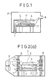
- Fig. 1 is a sectional view showing an example of the present invention.
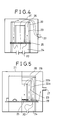
- Figs. 2(a) and 2(b) are sectional views showing other example of the present invention.
- Fig. 2(a) is a sectional view and
- Fig. 2(b) is a plan view.
- Fig. 3 is a schematic view showing a bearer for a material to be fired.
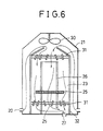
- Figs. 4 to 6 are each a sectional view showing an example of a firing furnace in which a cylindrical material is fired.
- Fig. 7 is a drawing showing other example of the present invention.
- Fig. 8 is a sectional view showing an example of a bottomed cylindrical superconductive material having an inlet for introducing a sensor therein.
- Fig. 9 is a drawing showing still other example of the present invention.
- Fig. 10 is a sectional view showing other example of a bottomed cylindrical superconductive material having an inlet for introducing a sensor therein.
- Figs. 11 to 13 are each a sectional view showing an example of a bell-shaped furnace wherein a cylindrical material is fired.
- Figs. 14 to 15 are each a sectional view showing a conventional firing furnace.
- Fig. 16 is a drawing showing the surface condition of a material to be fired when the material is fired in a conventional firing furnace.
- Fig. 1 is a sectional view of a firing furnace as an example of the present invention, having therein a gas passage formed by a jig.
- An oxygen-rich gas is introduced into a firing furnace 2 through a gas inlet 1 and passes through a gas passage 3 formed in the furnace 2 by a jig 7′.
- a material 4 to be fired In the gas passage 3 is placed a material 4 to be fired.
- the oxygen-rich gas is contacted with the material 4 to be fired, in a unidirectional flow and then discharged out of the firing furnace 2 through a gas outlet 8.
- the gas flow in the firing furnace 2 has no turbulence and the contact of the oxygen-rich gas with the material 4 to be fired becomes uniform.
- the material 4 to be fired is always contacted with a gas of high oxygen concentration and oxidized, and the resulting oxide superconductive material contains a very small amount of unreacted carbon and has excellent superconductive property (Jc).
- Fig. 2 shows other example of the present invention, wherein straightening louvers are provided at the upstream and downstream sides of a firing furnace and a fan is provided downstream of the downstream side straightening louver.
- a gas passage 3 is formed in a firing furnace 2 by straightening louvers 5 and a fan 6; therefore, an oxygen-rich gas of high temperature introduced into the firing furnace is contacted with a material 4 to be fired, uniformly in a unidirectional flow, and there can be obtained an oxide superconductive material having excellent superconductive property (Jc).
- the material for the jig 7′ for formation of a gas passage provided in the firing furnace there are used alumina, recrystallized silicon carbide, zirconia, magnesia, fire brick, inorganic fiber board, etc.
- a material of small heat capacity is preferred because with such a material it is possible to make small the difference between the temperature of the material to be fired and the controlled temperature inside the firing furnace, as well as the delay of the temperatures of the jig 7′ and the material 4 to be fired, against the temperature of the atmosphere inside the furnace at the time of temperature increase or decrease.
- the gas flow rate at the surface of the material to be fired is desirably 5-100 cm/min.
- the temperature inside the furnace can be controlled more easily and becomes more uniform.
- the flow rate of unidirectional flow gas at the surface of the material to be fired is more than 100 cm/min, the volume of the preheating chamber necessary to keep uniform the temperature inside the furnace becomes too large, and such a volume is not preferable for industrial application.
- the flow rate of the unidirectional gas flow formed to remove the oxygen-lean gas layer present on the material to be fired is sufficiently 100 cm/min or less.
- the distance between the inner wall of the jig and the surface of the material to be fired be small in order to make good the contact between the gas flow and the material to be fired.
- a porous plate as shown in Fig. 3, as a bearer 7 for the material 4 to be fired is preferable because it enables the contact of the oxygen-rich gas even with the lower surface of the material to be fired and ensures uniform firing of the material to be fired.
- louvers constituting the straightening louver 5 at the gas inlet side be opened wide at the furnace outer side and narrow at the furnace inner side and the louvers constituting the straightening louver 5 at the gas outlet side be opened wide at the furnace inner side and narrow at the furnace outer side, because such opening of the louvers enables the concentration of the gas flow on the surface of the material to be fired and allows the good contact of the material to be fired, with the gas of unidirectional flow.
- a fan 6 be provided at the gas outlet side and the gas after firing be forcibly drawn by the suction of the fan in a unidirectional flow from the firing chamber 11 defined by a partition 10 and the straightening louvers 5. It is also preferable that a fan 6 be provided at the gas inlet side and thereby a gas be fed into the firing chamber 11 in a unidirectional flow. It is further preferable that two fans be provided at the gas inlet side and the gas outlet side and thereby the gas flow in the firing chamber 11 be made a unidirectional flow more forcibly.
- the surface of the material to be fired can be always contacted with a fresh gas and thereby the formation of an oxygen-lean gas layer can be prevented, the temperature distribution inside the firing chamber 11 becomes uniform, and there can be obtained an oxide superconductive material excellent in superconductivity and and low in unevenness of properties.
- Figs. 4 to 6 are each an example of a firing furnace used for firing of a cylindrical material.
- an oxygen-rich gas introduced through a gas inlet 20 is heated to a desired temperature at a heating chamber 24 provided beneath a firing chamber 23 formed by a sagger 22 made of a refractory and becomes a rising stream of unidirectional flow.
- the stream proceeds upward in contact with the surface of a cylindrical material 26 to be fired, placed on a bearer 25 made of a porous plate and is discharged out of a firing furnace 21 through a gas outlet 27.
- an oxygen-rich gas is heated at a heating chamber 24 and becomes a rising stream.
- the stream proceeds upward between an inner casing 22a and an outer casing 22b, and collides with a cover 28 of the outer casing 22b and becomes a downward stream.
- the stream proceeds downward in a unidirectional flow in a firing chamber 23 defined by the inner casing 22a, in contact with the surface of a cylindrical material 26 to be fired, leaves the firing chamber 23 out of the outer casing 22b through an opening 29 provided at the bottom of the casings 22a and 22b, and is discharged out of a firing furnace 21 through a gas outlet 27.
- Fig. 6 is an example of a firing furnace using a fan and straightening louvers, in which furnace a cylindrical material 26 to be fired is placed in a firing chamber 23 defined by a partition 32 and straightening louvers 31.
- An oxygen-rich gas introduced through a gas inlet 20 is heated in the vicinity of a heating element and becomes a rising stream.
- the stream is forcibly converted to a downward stream by a fan 30 provided at the top of a firing furnace 21.
- the downward stream is straightened by a straightening louver 31, proceeds downward in a unidirectional flow in contact with the surface of a cylindrical material 26 to be fired, placed on a bearer 25, and then is discharged out of the firing furnace 21 through a gas outlet 27 provided at the bottom of the firing furnace 21 inside a partition 32.
- Figs. 11 to 13 similarly to Figs. 4 to 6, each shows a sectional view of a firing furnace used for firing of a cylindrical material.
- a fan 43 is provided at the bottom of a bearer 42 in a muffle 41 of a bell-shaped furnace 50; a both ends-opened cylindrical material 44 to be fired is placed on the bearer 42; and an atmosphere in the muffle 41 is forcibly stirred by heat convection and the action of the fan to uniformize the atmosphere in the muffle 41.
- the atmosphere in the muffle 41 is circulated from the outer surface of the cylindrical material 44 to its inner surface in the order of C ⁇ D ⁇ E, whereby the firing atmosphere is substantially uniformized and uniform firing can be effected.
- the cylindrical material 44 to be fired is closed in one end and consists of a cylindrical substrate 44 and a layer 45 to become an oxide superconductive layer when fired, formed on the outer surface of the substrate 44 as shown in Fig. 12 or consists of a cylindrical substrate 44 and a layer 45 to become an oxide superconductive layer when fired, formed on the inner surface of the substrate 44 as shown in Fig. 13, the atmosphere in the muffle cannot be made substantially uniform even by the action of a fan and becomes turbulent when a conventional bell-shaped furnace is used; therefore, the layer to become an oxide superconductive layer when fired, formed on the cylindrical substrate cannot be fired in a uniform atmosphere and the cylindrical oxide superconductive material obtained cannot express excellent superconductivity.
- Figs. 7 to 10 show examples of the present invention for firing bottomed cylindrical materials.
- Fig. 7 shows an example of a firing furnace used for firing a bottomed cylindrical material.
- a bearer 42 consisting of a ring-shaped plate 60 and a circular plate 61 is provided in a muffle 41; a fan 43 is provided below the bearer 42; a both ends-opened cylindrical inorganic material 47 is placed on the ring-shaped plate 60 provided with a gap kept against the inner wall of the muffle 41; a material 46 to be fired, consisting of (a) a bottomed cylindrical substrate 44 and (b) a layer 45 to become an oxide superconductive layer when fired, formed on the outer surface of the substrate 44, is placed on the circular plate 61 provided with a gap kept against the ring-shaped plate 60.
- the furnace 10 is heated and the fan 43 is actuated to allow the atmosphere gas in the muffle 41 to produce a gas flow of A ⁇ B ⁇ C in the A, B and C zones defined by the muffle 41, the cylindrical inorganic material 47 and the material 46 to be fired.
- the flow rate of the gas flow of A ⁇ B ⁇ C is preferably 0.1-3.0 m/sec.
- the surface area of the material to be fired or the inside volume of the furnace and the sectional area of the gas passage are large, a large amount of a gas must be introduced in order for the introduced gas to have a sufficiently high velocity; this requires the use of a very large amount of a gas and the installation of a very large preheating chamber, which are not preferable in industrial application.
- the atmosphere inside the furnace is circulated by the fan provided inside the furnace, as in the case of the bell-shaped furnace, the amount of gas introduced can be small.
- the distribution of gas flow rate varies depending upon the thickness, composition and shape of the layer to become an oxide superconductive layer when fired and the type of atmosphere used for firing, but it is preferably controlled so as to fall usually in a range of 50-150% of the average flow rate by appropriately selecting the sizes of cylindrical inorganic material 47 and material 46 to be fired, the gaps between muffle 41 and cylindrical inorganic material 47 and between cylindrical inorganic mateiral 47 and material 46 to be fired, the type and gas-blowing capacity of fan 43, etc.
- the distribution of gas flow rate deviates from 50-150% of the average flow rate, the atmosphere in the muffle tends to become nonuniform and the distribution of superconductivity becomes nonuniform.
- the same operation applies also to a bottomed cylindrical material as shown in Fig. 8, having an inlet 48 for introducing a sensor or the like.
- a material 46 to be fired consisting of a bottomed cylindrical substrate 44 and a layer 45 to become an oxide superconductive layer when fired, formed on the inner surface of the substrate 44.
- a bearer 42 is provided in a muffle 41, the bearer 42 consisting of (a) a ring-shaped plate 62 contacting with the inner wall of the muffle 41 and (b) a ring-shaped plate 63 provided with a gap kept against the ring-shaped plate 62, a fan 43 is provided below the bearer 42, a both ends-opened cylindrical inorganic material 47 is placed on the ring-shaped plate 63 of the bearer 42, and a material 46 to be fired, consisting of a bottomed cylindrical substrate 44 and a layer 45 to become an oxide superconductive layer when fired, formed on the inner surface of the substrate 44 is placed on the ring-shaped plate 62.
- the gas in the muffle 41 is allowed to produce a gas flow of A′ ⁇ B′ ⁇ C′ in the zones A′, B′ and C′ defined by the cylindrical inorganic material 47 and the material 46 to be fired, whereby the composition and temperature of the gas contacting with the layer 45 to become an oxide superconductive layer when fired are made uniform.
- the distribution of gas flow rate in the zones A′, B′ and C′ is controlled to be in a range of 50-150% of the average gas flow rate.
- the same operation applies also to a bottomed cylindrical material as shown in Fig. 10, having an inlet 48 for introducing a sensor or the like.
- the muffle 41 may be omitted.
- a material 46 to be fired consisting of a bottomed cylindrical substrate 44 and a layer 45 to become an oxide superconductive layer when fired is allowed to act also as a muffle;
- a cylindrical inorganic material 47 is provided inside the material 46 to be fired;
- the gas in the material 46 is allowed to produce a gas flow of A′ ⁇ B′ ⁇ C′; whereby the composition and temperature of the gas contacting with the layer 45 to become an oxide superconductive layer when fired are made uniform.
- the muffle of bell-shaped furnace can be usually made of a stainless steel (e.g. SUS 310S, SUS 430) or a metal (e.g. Inconel).
- the both ends-opened cylindrical inorganic material is preferably constituted generally by a ceramic (e.g. zirconia ZrO2, alumina Al2O3), a metal (e.g. Inconel, stainless steel), an emameled metal, an inorganic fiber board or their combination; and there is selected a material which is not deteriorated at the firing temperature used or by the firing gas employed.
- the layer to become an oxide superconductive layer when fired can be formed using materials selected so as to be able to give an oxide superconductive material, according to a known method such as spray coating, doctor blade coating, dip coating or the like.
- the oxide superconductive material is not particularly restricted and can be, for example, any of (a) rare earth element-containing oxide superconductive materials of M-Ba-Cu-O type having a perovskite structure wherein M is at least one rare earth element selected from Sc, Y and lanthanides such as La, Eu, Gd, Er, Yb, Lu and the like, and (b) bismuth -containing oxide superconductive materials having a composition represented by Bi2Sr2Ca1Cu2O x or Bi2Sr2Ca2Cu3O x .
- the substrate can be any as long as it can keep the mechanical strength of the above oxide superconductive material.
- the substrate can be any as long as it can keep the mechanical strength of the above oxide superconductive material.
- ceramics such as ZrO2, titania (TiO2) and the like, as well as metals such as SUS 430, SUS 310, SUS 304, Inconel, Incolloy, Hastelloy and the like.
- metals such as SUS 430, SUS 310, SUS 304, Inconel, Incolloy, Hastelloy and the like.
- an intermediate layer acting as a protective material and an adhesive made of a glass or a nobel metal (e.g. Au, Ag, Pt).
- the type, thickness, etc. of the intermediate layer can be selected depending upon the use purpose, etc. of the oxide superconductive material obtained.
- firing is generally effected by using an oxygen-containing gas and allowing the gas to produce a desired gas flow.
- the firing temperature can be appropriately selected depending upon the type, etc. of the oxide superconductive material used.
- the firing of a bismuth -containing oxide superconductive material can be generally effected by partially melting the material at 875-900°C in a uniform oxygen-containing atmosphere, annealing the partial melt at a temperature of 850°C or less to give rise to crystallization, converting the atmosphere gas to nitrogen and heat-treating the crystal at a temperature of 700°C or less in a uniform nitrogen atmosphere.
- a material to be fired which became an oxide superconductive material when fired there was used a Y-Ba-Cu-O type compound shaped into a size of 300 mm x 300 mm x 5 mm.
- a gas passage was formed in a firing furnace by a jig which was a combination of a lightweight fire brick and an inorganic fiber, as shown in Fig. 1.
- the above compound was placed in the gas passage, and firing was effected under the firing conditions as shown in Table 1, to obtain oxide superconductive materials having properties as shown in Table 1.
- Firing was effected under the same conditions as in Examples 1-7 except that the formation of gas passage in firing furnace was replaced by installation of straightening louvers and fan in firing furnace, as shown in Fig. 2. The results are shown in Table 1.
- Firing was effected under the same conditions as in Examples 8-14 except that the formation of gas passage in firing furnace was replaced by installation of straightening louvers and fan in firing furnace, as shown in Fig. 2. The results are shown in Table 1.
- Powders of Bi2O3, SrCO3 and CuO each as a starting material for Bi-containing oxide superconductive material were mixed in amounts giving a composition of Bi2Sr2CaCu2O x and then calcinated.
- the calcinated product was ground by a trommel together with ZrO2 flint pebbles using isopropyl alcohol as a solvent, to obtain a starting material powder for Bi-containing oxide superconductive material.
- a cylindrical substrate having a shape as shown in Table 3 was prepared using Inconel 625, SUS 430 or SUS 310S each of 1.98 mm in thickness.
- an intermediate layer consisting of a glass layer and a noble metal (Ag) layer or of the latter layer alone.
- Au noble metal
- On the intermediate layer was spray-coated or brush-coated the above-obtained powder, whereby a layer to become a Bi-containing oxide superconductive material when fired was formed so that the layer thickness after firing became about 300 ⁇ m.
- Table 3 The details of the constitution and formation method of each cylindrical material are shown in Table 3.
- the fired product was annealed to about 800°C at a cooling rate of 0.5°C/min to crystallize it.
- the lengths of the sensor inlets in Examples 39-41 and Comparative Examples 21-23 were 100 mm (Example 39 and Comparative Example 21), 320 mm (Example 40 and Comparative Examples 22 and 23) and 60 mm (Example 41).
- the atmosphere gas was converted to an oxygen-lean gas and the crystal was heat-treated at 450-700° C to obtain cylindrical oxide superconductive materials containing Bi.
- both ends-opened cylindrical materials even when fired in a conventional bell-shaped furnace, give oxide superconductive materials which are uniform and which have substantially uniform Jc values (Comparative Examples 13-16).
- bottomed cylindrical materials consisting of (a) a bottomed cylindrical substrate and (b) a layer to become an oxide superconductive layer when fired, formed on either surface (outer or inner) of the cylindrical substrate, give oxide superconductive materials, having low Jc values locally and are difficult to fire uniformly (Comparative Examples 17-23).
- bottomed cylindrical mateirals consisting of (a) a bottomed cylindrical substrate and (b) a layer to become a Bi-containing oxide superconductive layer when fired, formed on either surface (outer or inner) of the cylindrical substrate, give uniform oxide superconductive materials.
Landscapes
- Engineering & Computer Science (AREA)
- Chemical & Material Sciences (AREA)
- Ceramic Engineering (AREA)
- Manufacturing & Machinery (AREA)
- Materials Engineering (AREA)
- Structural Engineering (AREA)
- Organic Chemistry (AREA)
- Mechanical Engineering (AREA)
- General Engineering & Computer Science (AREA)
- Inorganic Compounds Of Heavy Metals (AREA)
- Compositions Of Oxide Ceramics (AREA)
- Superconductors And Manufacturing Methods Therefor (AREA)
Applications Claiming Priority (4)
| Application Number | Priority Date | Filing Date | Title |
|---|---|---|---|
| JP2060616A JPH03261668A (ja) | 1990-03-12 | 1990-03-12 | 酸化物超電導体の焼成方法及びその装置 |
| JP60616/90 | 1990-03-12 | ||
| JP2411178A JPH0796467B2 (ja) | 1990-12-17 | 1990-12-17 | 底付筒状酸化物超電導体の焼成方法 |
| JP411178/90 | 1990-12-17 |
Publications (2)
| Publication Number | Publication Date |
|---|---|
| EP0451950A1 true EP0451950A1 (de) | 1991-10-16 |
| EP0451950B1 EP0451950B1 (de) | 1995-05-31 |
Family
ID=26401694
Family Applications (1)
| Application Number | Title | Priority Date | Filing Date |
|---|---|---|---|
| EP91302012A Expired - Lifetime EP0451950B1 (de) | 1990-03-12 | 1991-03-11 | Verfahren zur Herstellung von supraleitendem Oxidmaterial durch Brennen und Vorrichtung dafür |
Country Status (4)
| Country | Link |
|---|---|
| US (1) | US5173478A (de) |
| EP (1) | EP0451950B1 (de) |
| CA (1) | CA2037765C (de) |
| DE (1) | DE69110078T2 (de) |
Families Citing this family (2)
| Publication number | Priority date | Publication date | Assignee | Title |
|---|---|---|---|---|
| JP2601069B2 (ja) * | 1991-08-08 | 1997-04-16 | 株式会社村田製作所 | セラミック成形体の焼成方法及び焼成装置 |
| FR3046555B1 (fr) * | 2016-01-07 | 2021-04-16 | Snecma | Procede de traitement thermique d'une preforme en poudre, et outillage permettant de le mettre en oeuvre |
Family Cites Families (5)
| Publication number | Priority date | Publication date | Assignee | Title |
|---|---|---|---|---|
| US1336762A (en) * | 1920-01-15 | 1920-04-13 | American Dressler Tunnel Kilns | Ware-support for ceramic firing |
| US2789808A (en) * | 1954-11-05 | 1957-04-23 | Lee Wilson | Method of and apparatus for controlling circulation of furnace atmosphere |
| JPS62104049A (ja) * | 1985-10-30 | 1987-05-14 | Mitsubishi Electric Corp | ベ−キング炉装置 |
| US4854860A (en) * | 1987-12-02 | 1989-08-08 | Gas Research Institute | Convective heat transfer within an industrial heat treating furnace |
| JPH0259048A (ja) * | 1988-08-24 | 1990-02-28 | Yokohama Rubber Co Ltd:The | 酸素濃度調整装置を備えた熱風恒温槽 |
-
1991
- 1991-03-07 CA CA002037765A patent/CA2037765C/en not_active Expired - Fee Related
- 1991-03-11 EP EP91302012A patent/EP0451950B1/de not_active Expired - Lifetime
- 1991-03-11 DE DE69110078T patent/DE69110078T2/de not_active Expired - Fee Related
- 1991-03-11 US US07/667,925 patent/US5173478A/en not_active Expired - Fee Related
Non-Patent Citations (4)
| Title |
|---|
| DERWENT ACCESSION NO. 90-072 443 (10), Questel Telesystems WPI DERWENT PUBLICATIONS LTD., London and JP A 2 26 825 * |
| DERWENT ACCESSION NO. 90-118 443 (16), Questel Telesystems WPI DERWENT PUBLICATIONS LTD., London * |
| DERWENT ACCESSION NO. 90-118 443 (16), Questel Telesystems WPI DERWENT PUBLICATIONS LTD., London and JP A 2 64 023 * |
| DERWNT ACCESSION NO. 90-072 443 (10), Questel Telesystems WPI DERWENT PUBLICATIONS LTD., London * |
Also Published As
| Publication number | Publication date |
|---|---|
| DE69110078T2 (de) | 1996-01-11 |
| DE69110078D1 (de) | 1995-07-06 |
| CA2037765C (en) | 1995-02-07 |
| EP0451950B1 (de) | 1995-05-31 |
| US5173478A (en) | 1992-12-22 |
Similar Documents
| Publication | Publication Date | Title |
|---|---|---|
| EP0609920B1 (de) | Oxidischer Supraleiter | |
| US5540959A (en) | Process for preparing a coated substrate | |
| US20090196996A1 (en) | Coated member and method of manufacture | |
| JPH08511613A (ja) | セラミックを基とする電子素子を製造するための方法および装置 | |
| EP0305820A2 (de) | Verfahren zur Herstellung eines Supraleiters | |
| EP0451950A1 (de) | Verfahren zur Herstellung von supraleitendem Oxidmaterial durch Brennen und Vorrichtung dafür | |
| US5304534A (en) | Method and apparatus for forming high-critical-temperature superconducting layers on flat and/or elongated substrates | |
| US4070542A (en) | Production of beta-alumina ceramic articles and furnace therefor | |
| US4865832A (en) | Molybdenum oxide whiskers and a method of producing the same | |
| EP0558268A1 (de) | Thallium-Kalzium-Barium-Kupfer-Oxyd-Supraleiter mit Silber und Verfahren | |
| JPH0796467B2 (ja) | 底付筒状酸化物超電導体の焼成方法 | |
| US5270296A (en) | High critical temperature superconducting wire with radially grown crystallites | |
| JPH0487181A (ja) | セラミックヒータ及びその製造法 | |
| KR910009198B1 (ko) | 초전도 성형체의 제조방법 | |
| US4350651A (en) | Process for the rapid sintering of ceramic components and a kiln for carrying out said process | |
| US6031207A (en) | Sintering kiln | |
| US3609199A (en) | Push-through furnace with graphite rod heating | |
| RU2148866C1 (ru) | Способ получения длинномерного провода с высокотемпературным сверхпроводящим покрытием | |
| JP2585667B2 (ja) | 磁気シールド用超電導材の製造方法 | |
| US3420707A (en) | Deposition of niobium stannide | |
| JPH03261668A (ja) | 酸化物超電導体の焼成方法及びその装置 | |
| JPH0339458A (ja) | 金属一酸化物超電導複合体及びその製造方法 | |
| JPH01186510A (ja) | 超電導材 | |
| JPH04294600A (ja) | 酸化物超電導筒状磁気シールド体及びそのための酸化物超電導筒状体の焼成方法 | |
| JPH01225013A (ja) | 酸化物超電導成形体の製造方法 |
Legal Events
| Date | Code | Title | Description |
|---|---|---|---|
| PUAI | Public reference made under article 153(3) epc to a published international application that has entered the european phase |
Free format text: ORIGINAL CODE: 0009012 |
|
| AK | Designated contracting states |
Kind code of ref document: A1 Designated state(s): BE DE FR GB SE |
|
| 17P | Request for examination filed |
Effective date: 19910909 |
|
| 17Q | First examination report despatched |
Effective date: 19930730 |
|
| GRAA | (expected) grant |
Free format text: ORIGINAL CODE: 0009210 |
|
| AK | Designated contracting states |
Kind code of ref document: B1 Designated state(s): BE DE FR GB SE |
|
| REF | Corresponds to: |
Ref document number: 69110078 Country of ref document: DE Date of ref document: 19950706 |
|
| ET | Fr: translation filed | ||
| PGFP | Annual fee paid to national office [announced via postgrant information from national office to epo] |
Ref country code: GB Payment date: 19960229 Year of fee payment: 6 |
|
| PGFP | Annual fee paid to national office [announced via postgrant information from national office to epo] |
Ref country code: FR Payment date: 19960315 Year of fee payment: 6 |
|
| PGFP | Annual fee paid to national office [announced via postgrant information from national office to epo] |
Ref country code: SE Payment date: 19960318 Year of fee payment: 6 |
|
| PGFP | Annual fee paid to national office [announced via postgrant information from national office to epo] |
Ref country code: DE Payment date: 19960320 Year of fee payment: 6 Ref country code: BE Payment date: 19960320 Year of fee payment: 6 |
|
| PLBE | No opposition filed within time limit |
Free format text: ORIGINAL CODE: 0009261 |
|
| STAA | Information on the status of an ep patent application or granted ep patent |
Free format text: STATUS: NO OPPOSITION FILED WITHIN TIME LIMIT |
|
| 26N | No opposition filed | ||
| PG25 | Lapsed in a contracting state [announced via postgrant information from national office to epo] |
Ref country code: GB Effective date: 19970311 |
|
| PG25 | Lapsed in a contracting state [announced via postgrant information from national office to epo] |
Ref country code: SE Effective date: 19970312 |
|
| PG25 | Lapsed in a contracting state [announced via postgrant information from national office to epo] |
Ref country code: BE Effective date: 19970331 |
|
| BERE | Be: lapsed |
Owner name: NGK INSULATORS LTD Effective date: 19970331 |
|
| GBPC | Gb: european patent ceased through non-payment of renewal fee |
Effective date: 19970311 |
|
| PG25 | Lapsed in a contracting state [announced via postgrant information from national office to epo] |
Ref country code: FR Free format text: LAPSE BECAUSE OF NON-PAYMENT OF DUE FEES Effective date: 19971128 |
|
| PG25 | Lapsed in a contracting state [announced via postgrant information from national office to epo] |
Ref country code: DE Effective date: 19971202 |
|
| EUG | Se: european patent has lapsed |
Ref document number: 91302012.9 |
|
| REG | Reference to a national code |
Ref country code: FR Ref legal event code: ST |