EP0451959A2 - Dispositif de levage d'une tête magnétique pour disque dur - Google Patents
Dispositif de levage d'une tête magnétique pour disque dur Download PDFInfo
- Publication number
- EP0451959A2 EP0451959A2 EP91302112A EP91302112A EP0451959A2 EP 0451959 A2 EP0451959 A2 EP 0451959A2 EP 91302112 A EP91302112 A EP 91302112A EP 91302112 A EP91302112 A EP 91302112A EP 0451959 A2 EP0451959 A2 EP 0451959A2
- Authority
- EP
- European Patent Office
- Prior art keywords
- wire
- lifting wire
- disk
- slider
- flexure
- Prior art date
- Legal status (The legal status is an assumption and is not a legal conclusion. Google has not performed a legal analysis and makes no representation as to the accuracy of the status listed.)
- Granted
Links
Images

Classifications
-
- G—PHYSICS
- G11—INFORMATION STORAGE
- G11B—INFORMATION STORAGE BASED ON RELATIVE MOVEMENT BETWEEN RECORD CARRIER AND TRANSDUCER
- G11B21/00—Head arrangements not specific to the method of recording or reproducing
- G11B21/02—Driving or moving of heads
- G11B21/12—Raising and lowering; Back-spacing or forward-spacing along track; Returning to starting position otherwise than during transducing operation
Definitions
- the present invention relates to slider lifters for disk drives.
- Such slider lifters are for physically lifting sliders with read/write heads off information storage discs during startup and shutdown.
- Disk drive machines record and reproduce information stored on a recording media.
- Typical hard disk drives often referred to as Winchester disk drives include one or more vertically aligned, spaced apart, rotating information storage disks, each having at least one associated slider with magnetic read/write head adapted to transfer information between the disk and an external computer system.
- the information storage disks are journalled about a spindle motor assembly capable of rotating the disks at high speeds.
- the sliders are carried by a plurality of vertically-aligned, elongated flexure arms that in turn are carried by a head positioner assembly.
- the head positioner assembly is adapted to move the sliders back and forth in unison across the faces of the vertically-aligned disks.
- the head positioner assembly is traditionally either rotationally mounted or takes the form of a carriage that is free to move back and forth along a single axis. In either case, the head positioner assembly is adapted to position the heads precisely relative to the magnetic information storage disks.
- the sliders rest on landing zones on the surface of their associated disks when the power is off.
- the drive unit is powered up and the disks begin to rotate.
- the sliders rise slightly off the landing zone under the lifting influence of a small air bearing which is created by the speed of rotation of the disks.
- the sliders remain floating above the disks and are said to "fly" over the disks, thereby preventing wear on the disk surfaces and potential destruction of the data.
- a shape memory alloy such as Ti-Ni alloy, has a high temperature austenitic phase wherein the crystal structure is body centre cubic. In the austenitic phase, the alloy is very strong and is not easily deformed. When cooled below its transformation temperature, the austenitic structure undergoes a diffusionless shear transform into a highly twinned martensitic crystal structure. In the martensitic phase, the alloy is easily deformed by the application of a small external force.
- the martensitic phase When the alloy is heated through its transformation temperature, the martensitic phase is elastically returned to the austenitic phase (referred to as an inverse transformation) according to a given ordered crystal and orientation law.
- a notable characteristic of the alloy is the extremely large recovery force that is generated when returning to the austenitic phase. Therefore, the employment of a resilient force as a bias force capable of deforming the alloy in its martensitic phase permits the alloy to be used as a reversible actuator with temperature cycling. Further, because the recovery force which is generated with the return of the austenitic phase is quite large, it is possible to take advantage of the recovery force to do work.
- US-A-4,605,979 discloses several proposed lifters for lifting the flexure to unload the slider.
- Each of the disclosed proposals uses a resilient biasing member in combination with shape memory alloy to load and unload the slider.
- a wire formed of shape memory metal extends forward from the guide bar upon which a load arm (flexure) is mounted.
- the wire is coated with a silicone resin which serves as the resilient biasing member.
- the silicone resin also serves to insulate thermally the wire.
- such an arrangement has the drawback of requiring a delicate coating of the shape memory wires in their martensitic state which adds to the complexity and costs of assembly.
- the present invention seeks to overcome the problems encountered by the prior art proposals.
- One object is to provide a compact slider lifter arrangement for disk drives that is capable of lifting sliders within a stack of tightly spaced, small diameter disks.
- Another object is to provide a slider lifter whose use does not necessitate an alteration in basic flexure design.
- Yet another object is to provide a slider lifter that is easy to assemble and has a low parts count.
- a slider lifter assembly for a disk drive assembly is characterised by a pair of support arms extending outward adjacent opposite sides of a flexure arm extending outwardly beyond the arms to carry a slider and transducer for transferring information to and from an information storage disk and a lifting wire strung between the opposing support arms adjacent the flexure arm, the lifting wire being formed from a shape memory alloy having martensitic and austenitic phase conditions, wherein the lifting wire co-operates with the flexure arm so that, when the lifting wire is in a first phase condition, the lifting wire lifts the flexure arm to lift the slider from the disk surface, and when the wire is in a second phase condition, the flexure arm deforms the lifting wire so that the slider is allowed to rest on or adjacent to the disk surface, or to fly over the disk surface free of positioning influence by the lifting wire.
- a slider lifter arrangement for conventional disk drives uses an element of shape memory alloy to lift a transducer slider away from the surface of an associated disk.
- the slider lifter includes a wire support having a pair of extended wire support arms extending outward from a head positioning carriage adjacent opposite sides of a flexure arm that carries a slider.
- a lifting wire is strung between the opposing wire support arms in the space between the flexure arm and the disk surface.
- the lifting wire is formed from a shape memory alloy having martensitic and austenitic phase conditions.
- the wire cooperates with the flexure arm so that when the wire is in a first phase condition, it lifts the flexure arm sufficiently to lift the slider off the disk surface.
- the flexure arm deforms the lifting wire so that the slider is allowed to rest on the disk surface.
- the wire is selectively electrically heated to change its state from one phase condition to the other.
- the wire support is formed integrally with the flexure assembly.
- the lifting wire may take either a substantially U-shaped or a substantially straight orientation in the first phase condition.
- the lifting wire is also preferably coated with an insulating material.
- the flexure assembly includes a flexure arm, the pair of opposing support arms and a base portion having attachment means for coupling the flexure assembly to a positioning means.
- a disk drive comprising an information storage disk rotatably journalled about a spindle assembly, the information storage disk having a data storage surface; a slider transducer for transferring information between the data storage surface and an external system; carriage means for positioning the slider relative to the information storage disk; a flexure assembly coupled to the carriage means, the flexure assembly including a flexure arm that carries the slider and a pair of extended wire support arms extending outward from the carriage means adjacent opposite sides of the flexure arm, the flexure arm being designed such that when the disk is rotating at an operational speed, the slider flies above the surface of the disk and when the disk is stopped, the slider rests on or adjacent the surface of the disk; a housing for encasing the disk, flexure assembly, slider and carriage means; a lifting wire strung between the opposing wire support arms in a space between the flexure arm, and the disk surface, the lifting wire being formed from a shape memory alloy having martensitic and austenitic phase
- a slider lifter arrangement which is adapted to lift the read/write transducer heads in conventional disk drives off the disk surfaces during startup and shutdown operations.
- the lifter arrangement includes a pair of support arms disposed on opposite sides of a flexure arm that carries the read/write transducer head (hereinafter referred to as the slider).
- a lifting wire formed from a shape memory alloy is strung between the opposing support arms and extends between the flexure arm and its associated disk surface.
- a Winchester type disk drive incorporating the present invention includes one or more magnetic information storage disks journalled about a spindle motor assembly within a housing having upper and lower casing members (not shown). For clarity, in Figure 2, a portion only of each of three spaced apart information storage disks 20 is shown. Each information storage disk 20 has a multiplicity of concentric information storage tracks for recording information.
- the drive also includes a data read/write head and head positioner assembly.
- a head positioner assembly 22 is rotatably mounted between the upper and lower casing in one corner of the drive housing.
- the head positioner assembly 22 includes an E-block 23 having four vertically aligned and spaced apart support pads 25, each of which carries one or two flexure assemblies 30, each of which carries a magnetic read/write data head slider 27 for reading information from and writing information onto the information storage disks 20.
- One of the flexure assemblies functions as a servo arm flexure which carries a servo head for accurately positioning the remaining sliders 27 relative to the information storage tracks.
- a voice coil motor (not shown) is adapted to precisely rotate the head positioner assembly back and forth so that the magnetic and servo heads move across the information storage disks.
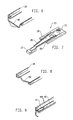
- the flexure assembly 30 ( Figure 3) includes a base portion 33 for coupling the flexure assembly 30 to its associated support pad 25, an integral elongated flexure arm 35 that carries the slider 27 at its distal end and a pair of integral support arms 38 that extend along, and are separated from, opposite sides of the flexure arm 35.
- a lifting wire 40 formed of a shape memory alloy is strung between the distal ends of opposing support arms 38.
- the wire 40 extends across and below the arm 35, having its ends bent up and then back to be secured to the ends of the arms 38.
- the lifting wire 40 is substantially of flattened U-shape, and is coupled to the distal ends of the support arms 38 in a manner which provides a good electrical connection between a power source and the lifting wire.
- the lifting wire 40 is formed from a shape memory alloy and is arranged to co-operate with the flexure arm to be movable between a lowered, non-lifting position ( Figure 4) and a raised lifting position ( Figure 5). In the lifting position, the lifting wire engages its associated flexure arm to "lift" the flexure arm 35 and its associated slider 27 away from the surface of its associated information storage disk 20.
- the resilient flexure arm 35 deforms the lifting wire 40 sufficiently to allow the slider 27 to rest upon the surface of the information storage disk 20, or to fly over the surface of the disk as the disk rotates, free of positioning influence from the lifting wire 40.
- the lifting wire 40 is fabricated from such a shape memory material as Ti-Ni.
- the shape memory alloy has a high temperature austenitic phase having a relatively high strength and a low temperature martensitic phase having a relatively low strength. At ambient and operational temperatures, the shape memory alloy is in its low temperature martensitic phase. When heated above its transition temperature, it reverts to its austenitic phase. Because the wire has a relatively small diameter, its temperature can readily be raised by passing an electrical current therethrough. The resistance of the small diameter wire is sufficient to accomplish the required heating.
- the diameter of the lifting wire 40 is selected such that when the wire is in the austenitic phase, the resilience and weight of the flexure cannot significantly deform the lifting wire.
- the resilience of conventional flexures can be used advantageously to co-operate with the lifting wire to deform the lifting wire sufficiently to allow the slider to rest upon or fly above the surface of the disk.
- the shape memory wire may be formed to have some memory in its martensitic phase. Accordingly, when the lifting wire 40 is allowed to cool to its martensitic phase, the sliders 27 are set down on the surface of the information storage disks 20.
- the electrical leads may take the form of a printed circuit ribbon cables 60 that are laid on the support arms 38. Good electrical and mechanical connections between the ribbon cable and the lifting wire 40 may be accomplished by soldering to form solder joint 61.
- the U-shape of the lifting wire 40 is particularly useful in drives requiring a relatively large displacement of the flexures.
- Figure 6 diagrammatically shows the deformation that can occur within the lifting wire 40.
- the solid lines represent the position of the lifting wire in the hot austenitic phase, while the dashed lines represent the position of the lifting wire in the cold martensitic phase. It is noted that very little cantilevered "bend" occurs in the leg portions of the U-shaped member that are coupled directly to the support arms 38. Rather, there is considerable torsion. This allows the base portion of the U-shaped lifting wire to act like a bending beam.
- U-shaped member 38 will vary a great deal depending upon the desired stroke for the lifting wire and the design of the flexure arm 35.
- a 6 mil diameter U-shaped lifting wire having a length of 0.635 mm (0.025 inch) extending beyond the support arms 38 and a width of 4.7625 mm (0.1875 inch) may have a stroke of approximately 0.508 mm (0.020 inch).
- the information storage disks 20 within a disk pack are typically spaced as close together as the flexure design allows in order to minimise the required disk size. Therefore, in many disk drives such as most mini 2.5 inch (63.5 mm) disk drives, the flexures extend nearly parallel to the disk surface and accordingly strokes of 20 mils are not required. Indeed, in some applications, such a long stroke is undesirable. This is because, as indicated above, conventional sliders float about 0.2 micrometers above the surface of the disks which the associated transducer accesses. Although the actual floating height will vary somewhat between specific flexure designs, it is important to prevent the lifting wire from lifting the sliders too far above the disk surface so as not to interfere with the adjacent disk.
- a straight lifting wire 50 replaces the U-shaped lifting wire described in the previous embodiment.
- this is shown attached to the under-sides of two solid square section support arms 38 extending on either side of a flexure support 33 to which a flexure arm 35 is secured.
- the lifting wire 50 is supported on the L-shaped support arms 38 integral with the flexure support 33 and flexure arm 35.
- the flexure assembly of the second embodiment is identical to the flexure assembly of the first embodiment. It should be readily apparent that the lifting wire 50 will not have as large of a stroke as the U-shaped lifting wire.
- a straight wire having a length of 5.08 mm (0.200 inches) will have a stroke of approximately 7 mils.
- the lifting wire must be electrically isolated from the metallic flexure arm 35 as well as the support arms 38. This may be accomplished by coating either the wire or the flexure arm with an insulating material, such as a spray type TEFLON (P.T.F.E.) based coating. Such coatings work well because they are easily applied, resist abrasion and can be cleaned easily in addition to having good electrical insulating properties.
- the lifting wire is coated with the insulating layer which has the advantage of thermally insulating the wire. Because heat loss from the lifting wire is of concern due to the wire's very thin diameter, such thermal insulation is advantageously reducing heat loss due to air turbulence.
- the latter is particularly advantageous because it gives the disk pack more time to slow to a stop.
- a potential source of power is the back emf of the spindle motor which rotates the disk pack. This back emf is generated during the power down phase of operation of the disk drive.
- the shape memory wire changes to its austenitic phase and lifts the slider off its associated disk.
- the wire 40 cools, and the flexure and slider reach their rest position.
- the lifting wire is stretched under the influence of the flexure, which acts as a leaf spring, until the slider is brought to rest on the surface of the disk or other parking area.
- shape memory alloys Because of their inherent characteristics, shape memory alloys remain relatively stiff until they are heated the first time. Therefore, when initially installed, the wire lifts the flexures somewhat which is helpful during the initial assembly of the drive.
- the lifting wire in both embodiments is disposed outside the periphery of the disk, so that no change of design of the flexure arm and slider is required.
- the present invention may be embodied in many other specific forms without departing from the scope of the invention as claimed. Particularly, it should be appreciated that the actual materials used for the various components, including the shape memory lifting wire may be widely varied.
- the positioning and arrangement of the various components including the support arms may also be widely varied. Indeed, the support arms may be carried by the E-block of the head positioning assembly as opposed to being formed as a part of the flexure assembly.
- the flexure assembly may be stamped as an integral piece as seen in Figure 3, or may include a flexure arm 35 attached to a flexure support 33 as seen in Figure 7.
Landscapes
- Supporting Of Heads In Record-Carrier Devices (AREA)
Applications Claiming Priority (2)
| Application Number | Priority Date | Filing Date | Title |
|---|---|---|---|
| US07/504,929 US5060099A (en) | 1990-04-05 | 1990-04-05 | Disc drive slider lifter using shape memory metals |
| US504929 | 1990-04-05 |
Publications (3)
| Publication Number | Publication Date |
|---|---|
| EP0451959A2 true EP0451959A2 (fr) | 1991-10-16 |
| EP0451959A3 EP0451959A3 (en) | 1992-09-02 |
| EP0451959B1 EP0451959B1 (fr) | 1996-08-28 |
Family
ID=24008299
Family Applications (1)
| Application Number | Title | Priority Date | Filing Date |
|---|---|---|---|
| EP91302112A Expired - Lifetime EP0451959B1 (fr) | 1990-04-05 | 1991-03-13 | Dispositif de levage d'une tête magnétique pour disque dur |
Country Status (7)
| Country | Link |
|---|---|
| US (1) | US5060099A (fr) |
| EP (1) | EP0451959B1 (fr) |
| JP (1) | JPH04281276A (fr) |
| KR (1) | KR910019024A (fr) |
| CA (1) | CA2031256A1 (fr) |
| DE (1) | DE69121622T2 (fr) |
| SG (1) | SG48055A1 (fr) |
Cited By (2)
| Publication number | Priority date | Publication date | Assignee | Title |
|---|---|---|---|---|
| EP0704837A1 (fr) * | 1994-09-01 | 1996-04-03 | Samsung Electronics Co., Ltd. | Commande d'une tête de disque rigide |
| EP0791917A3 (fr) * | 1996-02-20 | 1997-12-17 | Myrica (UK) Limited | Bras de suspension pour tête |
Families Citing this family (19)
| Publication number | Priority date | Publication date | Assignee | Title |
|---|---|---|---|---|
| JPH04167276A (ja) * | 1990-10-30 | 1992-06-15 | Teac Corp | 磁気ディスク装置 |
| JP3496223B2 (ja) * | 1991-12-13 | 2004-02-09 | ソニー株式会社 | 光磁気記録用摺動型磁気ヘッド |
| JP2587162B2 (ja) * | 1992-01-22 | 1997-03-05 | 富士通株式会社 | 磁気ディスク装置のヘッドアーム |
| US5535074A (en) * | 1992-05-04 | 1996-07-09 | Read-Rite Corporation | Disk drive apparatus having up and down head supsensions independently loadable into a space between immediately adjacent disks |
| US5810094A (en) * | 1996-05-09 | 1998-09-22 | W. L. Gore & Associates, Inc. | Head/pre-amp ribbon interconnect for data storage devices |
| KR100403045B1 (ko) * | 1996-06-05 | 2004-01-24 | 삼성전자주식회사 | 하드디스크드라이브의비접촉기동및정지를위한구조를갖는서스팬션어셈블리 |
| US5936803A (en) * | 1997-06-06 | 1999-08-10 | Western Digital Corporation | Disk drive having a mass balanced head gimbal assembly |
| US6212759B1 (en) * | 1997-10-10 | 2001-04-10 | Seagate Technology Llc | Automated assembly device for assembly of components of a disc drive |
| US5959801A (en) * | 1997-10-22 | 1999-09-28 | International Business Machines Corporation | Stiction reduction in disk drives using heating |
| US6473259B1 (en) | 1999-09-24 | 2002-10-29 | Seagate Technology Llc | Disk head height control |
| US6301073B1 (en) | 1999-11-18 | 2001-10-09 | International Business Machines Corporation | Device for preventing mechanical shock-induced damage between actuator and disk in computer hard disk drive |
| US6765765B2 (en) | 2000-10-04 | 2004-07-20 | Seagate Technology Llc | Head gimbal assembly with in-situs adjustable pitch and roll |
| US6954339B2 (en) | 2000-10-04 | 2005-10-11 | Seagate Technology Llc | Suspension assembly including a shape memory flexure element to adjust flexure or preload force |
| US6714377B2 (en) * | 2000-11-27 | 2004-03-30 | Seagate Technology Llc | Data storage device operated for reduced sliding contact |
| US6760182B2 (en) | 2001-02-19 | 2004-07-06 | Seagate Technology Llc | Temperature compensated fly height control |
| US6617542B2 (en) * | 2001-07-24 | 2003-09-09 | Hutchinson Technology, Inc. | Method of laser polishing surfaces on a head suspension assembly |
| JPWO2007110957A1 (ja) * | 2006-03-29 | 2009-08-06 | 富士通株式会社 | 磁気ディスク装置 |
| US8218265B2 (en) * | 2008-08-14 | 2012-07-10 | International Business Machines Corporation | Apparatus, system, and method for overcoming stiction in a magnetic tape device |
| US9027228B2 (en) * | 2012-11-29 | 2015-05-12 | Honeywell International Inc. | Method for manufacturing electromagnetic coil assemblies |
Family Cites Families (7)
| Publication number | Priority date | Publication date | Assignee | Title |
|---|---|---|---|---|
| BE791362A (fr) * | 1971-11-15 | 1973-05-14 | Xerox Corp | Dispositifs de charge de tete pour appareil d'entrainement de disque dememorisation |
| JPS59191177A (ja) * | 1983-04-13 | 1984-10-30 | Hitachi Ltd | スライダの自動ロ−デイング機構 |
| JPS6022781A (ja) * | 1983-07-18 | 1985-02-05 | Hitachi Ltd | ヘツド位置調整装置 |
| JPS60136073A (ja) * | 1983-12-23 | 1985-07-19 | Hitachi Ltd | 磁気デイスク装置 |
| US4605979A (en) * | 1984-03-22 | 1986-08-12 | Hitachi, Ltd. | Load/unload suspension device for a magnetic disc apparatus |
| US4684913A (en) * | 1986-09-05 | 1987-08-04 | Raychem Corporation | Slider lifter |
| US4787000A (en) * | 1987-07-08 | 1988-11-22 | Microscience International Cor | Head lifter for disk drive |
-
1990
- 1990-04-05 US US07/504,929 patent/US5060099A/en not_active Expired - Lifetime
- 1990-11-30 CA CA002031256A patent/CA2031256A1/fr not_active Abandoned
-
1991
- 1991-01-09 JP JP3000971A patent/JPH04281276A/ja active Pending
- 1991-03-06 KR KR1019910003569A patent/KR910019024A/ko not_active Withdrawn
- 1991-03-13 SG SG1996006693A patent/SG48055A1/en unknown
- 1991-03-13 DE DE69121622T patent/DE69121622T2/de not_active Expired - Fee Related
- 1991-03-13 EP EP91302112A patent/EP0451959B1/fr not_active Expired - Lifetime
Cited By (5)
| Publication number | Priority date | Publication date | Assignee | Title |
|---|---|---|---|---|
| EP0704837A1 (fr) * | 1994-09-01 | 1996-04-03 | Samsung Electronics Co., Ltd. | Commande d'une tête de disque rigide |
| US5719720A (en) * | 1994-09-01 | 1998-02-17 | Samsung Electronics Co., Ltd. | Head suspension mechanism and apparatus for its control |
| EP0791917A3 (fr) * | 1996-02-20 | 1997-12-17 | Myrica (UK) Limited | Bras de suspension pour tête |
| US5808837A (en) * | 1996-02-20 | 1998-09-15 | Myrica (Uk) Limited | Disk drives |
| EP0944040A1 (fr) * | 1996-02-20 | 1999-09-22 | Myrica (UK) Limited | Dispositif de limitation du mouvement d'un bras de suspension pour tête |
Also Published As
| Publication number | Publication date |
|---|---|
| DE69121622D1 (de) | 1996-10-02 |
| JPH04281276A (ja) | 1992-10-06 |
| SG48055A1 (en) | 1998-04-17 |
| US5060099A (en) | 1991-10-22 |
| DE69121622T2 (de) | 1997-01-16 |
| KR910019024A (ko) | 1991-11-30 |
| EP0451959B1 (fr) | 1996-08-28 |
| EP0451959A3 (en) | 1992-09-02 |
| CA2031256A1 (fr) | 1991-10-06 |
Similar Documents
| Publication | Publication Date | Title |
|---|---|---|
| EP0451959B1 (fr) | Dispositif de levage d'une tête magnétique pour disque dur | |
| US5023737A (en) | Disc drive slider lifter using shape memory materials | |
| US5463514A (en) | Disc drive slider lifter using shape memory metals | |
| US4605979A (en) | Load/unload suspension device for a magnetic disc apparatus | |
| US4684913A (en) | Slider lifter | |
| US6307719B1 (en) | Suspension assembly with adjustable gramload | |
| US6760182B2 (en) | Temperature compensated fly height control | |
| US6115214A (en) | Rotary snubber assembly for a disc drive | |
| US7474504B2 (en) | Magnetic head heating element in a disk drive | |
| US6952330B1 (en) | Dynamic flying attitude control using augmented gimbal | |
| US7154696B2 (en) | Tunable fly height using magnetomechanical effect in a magnetic head | |
| US6157520A (en) | Disc drive head suspension with gimbal contact feature for ramp load/unload | |
| US6320723B1 (en) | Protective cover for a disc drive printed circuit board wherein the cover and a circuit board component are thermally connected | |
| US6122130A (en) | Intelligent lubricant for ramp load/unload | |
| US20020114108A1 (en) | Apparatus and method for passive adaptive flying height control in a disc drive | |
| US6067208A (en) | Adjustment feature for load/unload alignment ramp assembly | |
| JP3565741B2 (ja) | ヘッド支持アーム、その製造方法及びデータ記録装置 | |
| KR20020025998A (ko) | 디스크 저장 장치용 슬라이더 | |
| US7068470B1 (en) | Composite head arm assembly with thermal control of gram load | |
| US6333828B1 (en) | Magnetic disk unit with slider suspension assemblies and head IC chips | |
| JP2931479B2 (ja) | 回転ディスク記録再生装置におけるロードアンロード機構 | |
| JPH03104069A (ja) | 磁界変調用磁気ヘッドロードアンロード装置 | |
| KR100434748B1 (ko) | 디스크 드라이브용 램프 로드 조립체 | |
| US6535356B1 (en) | Head lifter and method of operation | |
| JP4149993B2 (ja) | 記録媒体駆動装置およびランプ部材アセンブリ |
Legal Events
| Date | Code | Title | Description |
|---|---|---|---|
| PUAI | Public reference made under article 153(3) epc to a published international application that has entered the european phase |
Free format text: ORIGINAL CODE: 0009012 |
|
| AK | Designated contracting states |
Kind code of ref document: A2 Designated state(s): DE FR GB IT NL |
|
| PUAL | Search report despatched |
Free format text: ORIGINAL CODE: 0009013 |
|
| AK | Designated contracting states |
Kind code of ref document: A3 Designated state(s): DE FR GB IT NL |
|
| 17P | Request for examination filed |
Effective date: 19930210 |
|
| GRAG | Despatch of communication of intention to grant |
Free format text: ORIGINAL CODE: EPIDOS AGRA |
|
| 17Q | First examination report despatched |
Effective date: 19951212 |
|
| GRAH | Despatch of communication of intention to grant a patent |
Free format text: ORIGINAL CODE: EPIDOS IGRA |
|
| GRAH | Despatch of communication of intention to grant a patent |
Free format text: ORIGINAL CODE: EPIDOS IGRA |
|
| GRAA | (expected) grant |
Free format text: ORIGINAL CODE: 0009210 |
|
| AK | Designated contracting states |
Kind code of ref document: B1 Designated state(s): DE FR GB IT NL |
|
| REF | Corresponds to: |
Ref document number: 69121622 Country of ref document: DE Date of ref document: 19961002 |
|
| ET | Fr: translation filed | ||
| ET | Fr: translation filed | ||
| ITF | It: translation for a ep patent filed | ||
| PLBE | No opposition filed within time limit |
Free format text: ORIGINAL CODE: 0009261 |
|
| STAA | Information on the status of an ep patent application or granted ep patent |
Free format text: STATUS: NO OPPOSITION FILED WITHIN TIME LIMIT |
|
| 26N | No opposition filed | ||
| PG25 | Lapsed in a contracting state [announced via postgrant information from national office to epo] |
Ref country code: NL Effective date: 19971001 |
|
| PG25 | Lapsed in a contracting state [announced via postgrant information from national office to epo] |
Ref country code: FR Free format text: LAPSE BECAUSE OF NON-PAYMENT OF DUE FEES Effective date: 19971128 |
|
| NLV4 | Nl: lapsed or anulled due to non-payment of the annual fee |
Effective date: 19971001 |
|
| REG | Reference to a national code |
Ref country code: FR Ref legal event code: ST |
|
| REG | Reference to a national code |
Ref country code: GB Ref legal event code: 732E |
|
| PGFP | Annual fee paid to national office [announced via postgrant information from national office to epo] |
Ref country code: GB Payment date: 20010205 Year of fee payment: 11 |
|
| REG | Reference to a national code |
Ref country code: GB Ref legal event code: IF02 |
|
| PG25 | Lapsed in a contracting state [announced via postgrant information from national office to epo] |
Ref country code: GB Free format text: LAPSE BECAUSE OF NON-PAYMENT OF DUE FEES Effective date: 20020313 |
|
| PGFP | Annual fee paid to national office [announced via postgrant information from national office to epo] |
Ref country code: DE Payment date: 20020529 Year of fee payment: 12 |
|
| GBPC | Gb: european patent ceased through non-payment of renewal fee |
Effective date: 20020313 |
|
| PG25 | Lapsed in a contracting state [announced via postgrant information from national office to epo] |
Ref country code: DE Free format text: LAPSE BECAUSE OF NON-PAYMENT OF DUE FEES Effective date: 20031001 |
|
| PG25 | Lapsed in a contracting state [announced via postgrant information from national office to epo] |
Ref country code: IT Free format text: LAPSE BECAUSE OF NON-PAYMENT OF DUE FEES;WARNING: LAPSES OF ITALIAN PATENTS WITH EFFECTIVE DATE BEFORE 2007 MAY HAVE OCCURRED AT ANY TIME BEFORE 2007. THE CORRECT EFFECTIVE DATE MAY BE DIFFERENT FROM THE ONE RECORDED. Effective date: 20050313 |