EP0451984A2 - Ultraschallwandleranordnung - Google Patents
Ultraschallwandleranordnung Download PDFInfo
- Publication number
- EP0451984A2 EP0451984A2 EP91302583A EP91302583A EP0451984A2 EP 0451984 A2 EP0451984 A2 EP 0451984A2 EP 91302583 A EP91302583 A EP 91302583A EP 91302583 A EP91302583 A EP 91302583A EP 0451984 A2 EP0451984 A2 EP 0451984A2
- Authority
- EP
- European Patent Office
- Prior art keywords
- layers
- piezoelectric
- piezoelectric layers
- stacked
- ultrasonic
- Prior art date
- Legal status (The legal status is an assumption and is not a legal conclusion. Google has not performed a legal analysis and makes no representation as to the accuracy of the status listed.)
- Granted
Links
Images


Classifications
-
- B—PERFORMING OPERATIONS; TRANSPORTING
- B06—GENERATING OR TRANSMITTING MECHANICAL VIBRATIONS IN GENERAL
- B06B—METHODS OR APPARATUS FOR GENERATING OR TRANSMITTING MECHANICAL VIBRATIONS OF INFRASONIC, SONIC, OR ULTRASONIC FREQUENCY, e.g. FOR PERFORMING MECHANICAL WORK IN GENERAL
- B06B1/00—Methods or apparatus for generating mechanical vibrations of infrasonic, sonic, or ultrasonic frequency
- B06B1/02—Methods or apparatus for generating mechanical vibrations of infrasonic, sonic, or ultrasonic frequency making use of electrical energy
- B06B1/06—Methods or apparatus for generating mechanical vibrations of infrasonic, sonic, or ultrasonic frequency making use of electrical energy operating with piezoelectric effect or with electrostriction
- B06B1/0607—Methods or apparatus for generating mechanical vibrations of infrasonic, sonic, or ultrasonic frequency making use of electrical energy operating with piezoelectric effect or with electrostriction using multiple elements
- B06B1/0611—Methods or apparatus for generating mechanical vibrations of infrasonic, sonic, or ultrasonic frequency making use of electrical energy operating with piezoelectric effect or with electrostriction using multiple elements in a pile
- B06B1/0614—Methods or apparatus for generating mechanical vibrations of infrasonic, sonic, or ultrasonic frequency making use of electrical energy operating with piezoelectric effect or with electrostriction using multiple elements in a pile for generating several frequencies
-
- B—PERFORMING OPERATIONS; TRANSPORTING
- B06—GENERATING OR TRANSMITTING MECHANICAL VIBRATIONS IN GENERAL
- B06B—METHODS OR APPARATUS FOR GENERATING OR TRANSMITTING MECHANICAL VIBRATIONS OF INFRASONIC, SONIC, OR ULTRASONIC FREQUENCY, e.g. FOR PERFORMING MECHANICAL WORK IN GENERAL
- B06B1/00—Methods or apparatus for generating mechanical vibrations of infrasonic, sonic, or ultrasonic frequency
- B06B1/02—Methods or apparatus for generating mechanical vibrations of infrasonic, sonic, or ultrasonic frequency making use of electrical energy
- B06B1/06—Methods or apparatus for generating mechanical vibrations of infrasonic, sonic, or ultrasonic frequency making use of electrical energy operating with piezoelectric effect or with electrostriction
- B06B1/0607—Methods or apparatus for generating mechanical vibrations of infrasonic, sonic, or ultrasonic frequency making use of electrical energy operating with piezoelectric effect or with electrostriction using multiple elements
- B06B1/0622—Methods or apparatus for generating mechanical vibrations of infrasonic, sonic, or ultrasonic frequency making use of electrical energy operating with piezoelectric effect or with electrostriction using multiple elements on one surface
- B06B1/064—Methods or apparatus for generating mechanical vibrations of infrasonic, sonic, or ultrasonic frequency making use of electrical energy operating with piezoelectric effect or with electrostriction using multiple elements on one surface with multiple active layers
Definitions
- the present invention relates to an ultrasonic probe used for an ultrasonic test apparatus and, more particularly, to an ultrasonic probe system which is constituted by a stacked piezoelectric element and is capable of transmitting/receiving ultrasonic waves having different frequencies.
- An ultrasonic probe has a probe head mainly constituted by a piezoelectric element. This ultrasonic probe is used to obtain image data representing the internal state of a target object by radiating ultrasonic waves onto the target object and immediately receiving waves reflected from interfaces of the target object which have different acoustic impedances.
- An ultrasonic test apparatus using such an ultrasonic probe is used in practice as, e.g., a medical diagnosing apparatus for examining the inside of a human body, or an industrial test apparatus for inspecting flaws in welded metal portions.
- the diagnosing function of a medical diagnosing apparatus has been greatly improved owing to the development of "the color flow mapping (CFM) method" in addition to photography of a tomographic image (B mode image) of a human body.
- CFM color flow mapping
- blood flow rates in a heart, a liver, a carotid artery, and the like as targets are two-dimensionally displayed in color by using the Doppler effect.
- the CFM method has been used to diagnose all kinds of internal organs of a human body, such as the uterus, the kidney, and the pancreas. Further studies of the CFM method are now in progress to allow observation of even the movement of a coronary blood flow.
- the above-mentioned B mode image i.e., a tomographic image of a human body
- a high-resolution image be obtained with high sensitivity to allow an operator to clearly observe a physical change or a cavity as a slight morbid alteration.
- the Doppler mode for acquiring a CFM image or the like since echoes (waves) reflected by, e.g., microscopic blood cells, each having a diameter of several ⁇ m, are used, the resulting signal level is lower than that obtained in the B mode described above. For this reason, high-sensitivity performance is especially required.
- a reference frequency in this Doppler mode is set to be lower than the center frequency in the frequency band of an ultrasonic probe.
- duplex type ultrasonic probes are available from various manufacturers.
- a duplex type ultrasonic probe is designed such that two types of vibrators having different resonance frequencies are arranged in one ultrasonic probe.
- the specific band width of frequency components which is required to obtain a good B mode image, is 40% or more of its center frequency.
- a specific band width with respect to a center frequency at -6 dB is 40 to 50% in one-layer matching, and 60 to 70% in two-layer matching.
- specific band widths of 25% and 35% are respectively set in one-layer matching and two-layer matching. That is, if only the stacked piezoelectric element is used, the obtained specific band width is only about 1/2 that obtained when the single-layered piezoelectric element is used.
- a probe head is constituted by a stacked piezoelectric element formed by stacking a plurality of piezoelectric layers such that the polarization directions of every two adjacent piezoelectric layers are opposite to each other or the polarization directions of all the piezoelectric layers coincide with each other, and bonding electrodes to two end faces of the stacked layers in the stacking direction and to the interface between the respective piezoelectric layers.
- the probe head is designed to allow connection of a DC power supply capable of applying a voltage higher than the coercive electric field of each piezoelectric member to one set of every other stacked piezoelectric layers and capable of changing the polarity of the voltage.
- this probe head is constituted by a piezoelectric layer formed by stacking a plurality of piezoelectric members having predetermined polarization directions and the same thickness.
- the ultrasonic probe system is designed such that when a voltage higher than the coercive electric field of the piezoelectric layer is applied to each layer thereof, the polarity of the voltage is controlled to direct the electric fields of every two adjacent layers constituting the piezoelectric layer in substantially opposite directions or the electric fields of all the layers to the same direction, thereby selectively generating ultrasonic waves having a plurality of different frequencies.
- a turn over circuit and a DC power supply are connected to the stacked piezoelectric element, which is formed by stacking the plurality of piezoelectric layers on each other and bonding the electrodes to the two end faces of the stacked piezoelectric layers in the stacking direction and to the interface between the respective piezoelectric layers, so that the voltage higher than the coercive electric field of the piezoelectric member is applied to one set of every other stacked piezoelectric layers such that the polarization directions of every two adjacent piezoelectric layers are opposite to each other or the polarization directions of all the piezoelectric layers coincide with each other, and the polarity of the voltage is changed to change the direction of a corresponding electric field.
- the minimum (fundamental) resonance frequency differs depending on whether the polarization directions of one set of every other piezoelectric layers to which the DC power supply is connected coincide or are opposite to those of the other set of every other piezoelectric layers to which the DC power supply is not connected.
- each piezoelectric layer is represented by t
- the number of layers is represented by n
- the sound velocity of the piezoelectric member is represented by v
- the stacked piezoelectric element is equivalent to a one-layer piezoelectric element having a thickness nt.
- the polarization directions of every two adjacent piezoelectric layers are opposite to each other. In this case, when an arbitrary piezoelectric layer extends, an adjacent piezoelectric layer contracts.
- n/2-wavelength resonance occurs in such a manner that the two end faces of the piezoelectric element in the direction of thickness serve as loops of vibrations, and the middle point serves as a node. Therefore, the resulting resonance frequency is n times that obtained when the polarization directions coincide with each other.
- the present invention is characterized in that this resonance frequency conversion is performed by supplying a polarization turn over pulse and a sending pulse generated by a pulser constituting this ultrasonic probe system, and a "turn over" operation is performed within a blanking time, of a so-called system operating time, immediately before the reception mode of the system.
- This "blanking time” is a setting time of the system, during which data transmission and the like are performed.
- the blanking time varies depending on the type of an ultrasonic probe or a diagnosing apparatus, it is normally set to be 20 to 40 ⁇ s (see Fig. 5).
- the duration of time in which no transmission/reception of ultrasonic waves is performed is 10 to 30 ⁇ s. Since the polarization of each piezoelectric layer can be turned over by applying the voltage higher than the coercive electric field for several ⁇ s, this operation can be performed within 10 to 30 ⁇ s, for which no transmission/reception is performed.
- the frequencies of sending ultrasonic waves can be switched at the same timing as that in a conventional diagnosing apparatus, a high-resolution, high-frequency B mode signal and a high-sensitivity, low-frequency Doppler signal can be acquired at the same timing as that in the conventional diagnosing apparatus. Therefore, a B mode image constituted by this high-frequency wave and a CFM image constituted by this low-frequency wave can be obtained in real time.
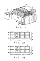
- acoustic matching layers 2, 3, and 4 and an acoustic lens 5 are formed on the ultrasonic radiation side of a stacked piezoelectric element 1, while a backing member 6 as a base of a probe head is formed on the rear surface side.
- the stacked piezoelectric element 1 is formed by stacking two piezoelectric layers on each other. An inner electrode is bonded to the interface between these piezoelectric layers, whereas outer electrodes are respectively bonded to both end faces of the element 1 in the stacking direction, i.e., one each of the upper and lower outer electrodes are formed.
- the acoustic matching layers 2, 3, and 4 and the acoustic lens 5 are formed on the piezoelectric layer, and the backing member 6 is formed under the piezoelectric layer. With this arrangement, the piezoelectric layer is sandwiched between these upper and lower members, thus constituting a probe head having an illustrated integrated structure.
- the thicknesses of the three matching layers 2, 3, and 4 are set to ensure matching on the high-frequency side. Such setting is performed to acquire a B mode signal on the high-frequency side and to broaden a sensitivity band.
- the stacked layers except for the acoustic lens 5 on the uppermost portion and the backing member 6 are formed into strips.
- a common ground electrode line (not shown) is soldered to one outer electrode, and signal lines of a flexible print plate 9 are soldered to the other outer electrode. More specifically, the pitch of the signal lines of the flexible print plate 9 is set to be 0.15 mm, which is an optimal value calculated in relation to a cutting operation by a dicing machine using a 30- ⁇ thick blade used for forming the above-mentioned strips.
- a DC power supply 18 capable of turning over the polarity is connected to the stacked piezoelectric element through polarity turn over common electrode lines 7 and 8 between one outer electrode and the inner electrode of the stacked piezoelectric layer to supply power to the electrodes of the head.
- the polarity of the DC power supply 18 connected to the stacked piezoelectric element is manually or automatically turned over, the polarization directions of every two adjacent stacked layers can be changed to substantially opposite directions regardless of whether the initial polarization directions of the adjacent piezoelectric layers are the same or opposite to each other. Therefore no special consideration need be given to the initial polarization directions of the piezoelectric layers connected to the DC power supply 18 capable of turning polarity over.
- Figs. 2A and 2B are enlarged sectional views, of the stacked piezoelectric element in Fig. 1, taken along a line A - A′.
- this stacked piezoelectric element' for example, two piezoelectric layers 11 and 12 are stacked on each other such that polarization directions (arrows) 13 and 14 oppose each other in an initial state.
- Outer electrodes 15 and 16 are bonded to two end faces of the element, i.e., the upper surface of the piezoelectric layer 11 and the lower surface of the piezoelectric layer 12, and an inner electrode 17 is bonded to the interface between the piezoelectric layers 11 and 12.
- the adjacent two piezoelectric layers have opposite polarization directions.
- the initial polarization directions of the piezoelectric layers of a stacked piezoelectric element may have same polarization direction, as polarization directions 13′ and 14′ in Fig. 2B, as long as the piezoelectric layers are connected to the above-mentioned DC power supply capable of turning polarity over.
- Each of the piezoelectric layers 11 and 12 is composed of a piezoelectric ceramic material, called a PZT ceramic material having a specific permittivity of 2,000, to have a thickness of 200 ⁇ m.
- the cross sections of the stacked piezoelectric element 1 constituting this probe head are arranged in an array of strips, as shown in Figs. 2A and 2B.
- the stacked piezoelectric element including matching layers (not shown), which are bonded to the upper surface is cut in the stacking direction (i.e., vertical direction) by a dicing machine using a blade. Thereafter, the cut portions are horizontally arranged at a predetermined pitch. In this case, the pitch is set to be 0.15 mm.
- Fig. 3A is a graph showing the frequency spectrum of an echo wave reflected by a reflector in water and measured by the "pulse echo method". According to this graph, a center frequency is about 7 MHz (an actual measurement value: 7.54 MHz), and a specific band of -6 dB corresponds to 52.9% of the center frequency. It is apparent from the values indicated by the graph that a frequency band wide enough to obtain a good B mode image by using an ultrasonic imaging apparatus using an ultrasonic probe can be obtained.
- Fig. 3B is a graph showing the frequency spectrum of an echo wave measured by the "pulse echo method", more specifically, a characteristic curve obtained when the polarization direction of a given piezoelectric layer is turned over by applying a DC voltage of 400 V to the layer for about 10 seconds by using a DC power supply capable of turning over polarity so that the polarization directions of all the piezoelectric layers are set to be the same.
- a center frequency of about 3.5 MHz an actual measurement value: 3.71 MHz
- a specific band of -6 dB corresponds to 51.9% of the center frequency.
- the center frequency of an echo wave is reduced to about 1/2. If a voltage having the opposite polarity is applied to a corresponding piezoelectric layer in this state, the polarization directions are restored to the initial state in this embodiment, i.e., the opposite directions.
- the present invention is not limited to the embodiment described above. Various changes and modifications can be made within the spirit and scope of the invention.
- the two-layered stacked piezoelectric element is used.
- a stacked piezoelectric constituted by three or more layers may be used.
- a plurality of piezoelectric layers are stacked on each other such that the polarization directions of every two adjacent layers are opposite to each other or the polarization directions of all the layers are the same, and a DC power supply capable of turning over the polarity by applying a voltage higher than the coercive electric field of a piezoelectric member to one set of every other layers of a stacked piezoelectric element in which electrodes are bonded to the two end faces in the stacking direction and the interface between the piezoelectric layers can be connected to the element.
- the polarization directions of the respective piezoelectric layers of the stacked piezoelectric element can be set to substantially desired directions, thereby realizing an ultrasonic probe system which can be used without limitation in terms of the initial polarization directions of piezoelectric layers.
- an ultrasonic probe system can be provided, which can transmit/receive ultrasonic waves having two different types of frequencies through the same plane of a probe head of an ultrasonic probe, and can simultaneously acquire a wideband B mode signal in a high-frequency region and a high-sensitivity Doppler signal in a low-frequency region.
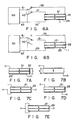
- Fig. 4 is a perspective view showing a schematic arrangement of an ultrasonic probe according to the second embodiment of the present invention.
- Acoustic matching layers 2, 3, and 4 and an acoustic lens 5 are formed on the ultrasonic radiation side of a stacked piezoelectric element 1, whereas a backing member 6 as a base of a probe head is formed on the rear surface side.
- the stacked piezoelectric element 1 is formed by stacking two piezoelectric layers on each other. An inner electrode is bonded to the interface between these piezoelectric layers, whereas outer electrodes are respectively bonded to both end faces of the element 1 in the stacking direction, i.e., one each of the upper and lower outer electrodes are formed.
- the acoustic matching layers 2, 3, and 4 and the acoustic lens 5 as upper members and the backing member 6 as a lower member are formed to sandwich the stacked piezoelectric layer, thus constituting a probe head having an integrated structure, as shown in Fig. 4.
- the thicknesses of the three matching layers 2, 3, and 4 are set to ensure matching on the high-frequency side. Such setting is performed to acquire a B mode signal on the high-frequency side and to broaden a sensitivity band.
- the stacked layers except for the acoustic lens 5 on the uppermost portion and the backing member 6 are formed into strips.
- a common ground electrode line is soldered to one outer electrode, and signal lines of a flexible print plate 9 are soldered to the other outer electrode. More specifically, the pitch of the signal lines of the flexible print plate 9 is set to be 0.15 mm, which is an optimal value calculated in relation to a cutting operation by a dicing machine using a 30- ⁇ thick blade used for forming the above-mentioned strips.
- a polarization turn over circuit 18 capable of turning over the polarity is used to supply power to the electrodes of this head.
- the circuit 18 includes a DC power supply connected to the stacked piezoelectric element through polarity turn over common electrode lines 7 and 8 between one outer electrode and the inner electrode of the stacked piezoelectric layer.
- the polarity of the DC power supply of the polarization turn over circuit 18 connected to the stacked piezoelectric element is manually or automatically turned over, the polarization directions of every two adjacent stacked layers can be changed to opposite directions regardless of whether the initial polarization directions of the adjacent piezoelectric layers are the same or opposite to each other. Therefore, no special consideration need be given to the initial polarization directions of the piezoelectric layers connected to the DC power supply.
- Fig. 5 is a timing chart of voltage pulses for driving the ultrasonic probe according to the present invention.
- a blanking time as a setting time of the system is 30 ⁇ s.
- a sending pulse is applied 10 ⁇ s after the end of this blanking time. Therefore, a polarization turn over operation has a margin of about 20 ⁇ s.
- a turn over pulse is applied only for 15 ⁇ s. Since this piezoelectric element has a coercive electric field of 1 kV/mm, a voltage of ⁇ 200 V is applied. Note that the polarization turn over circuit is constituted by an FET switch.
- FIGs. 6A and 6B are circuit diagrams, each showing a schematic connecting state of an ultrasonic probe according to the present invention.
- a piezoelectric vibrator 1 is constituted by a stacked layer (piezoelectric layer) formed by bonding two piezoelectric ceramic members, as piezoelectric elements having substantially the same thickness, to each other in the direction of thickness.
- Two different types of frequency bands are excited from the single vibrator 1 by controlling the polarities of driving pulses to be respectively applied to electrodes 21, 22, and 23 formed on the interfaces between the layers of this two-layer piezoelectric vibrator 1.
- a pulser/receiver circuit for processing reception signals of a driving pulse source and the vibrator has two terminals, i.e., a GND terminal 62 and a signal terminal 61.
- the three terminals of the vibrator 1 are connected to the two terminals of the pulser/receiver circuit through two switches, as shown in Figs. 6A and 6B. Since the resonance frequency of the vibrator 1 is changed by operating these switches, two types of frequencies can be excited. The principle of this operation will be described below with reference to Figs. 7A to 7E.
- Fig. 7A shows a piezoelectric vibrator of this embodiment.
- Fig. 7B shows a single-layer piezoelectric vibrator equivalent to the vibrator in Fig. 7A.
- a two-layered vibrator is designed such that the stacked layers have the same polarization direction, and a pulse is applied between electrodes 21 and 23 respectively formed on the upper and lower surfaces of the piezoelectric element.
- An inner electrode 22 is formed in an electrically floating state.
- the resonance frequency of the vibrator is determined by a total thickness t of the two-layered vibrator, and the thickness of each electrode can be substantially neglected as compared with the thickness of the ceramic layer, the thickness of the vibrator in Fig. 7B is equivalent to the thickness t .
- the resonance frequency and the electric impedance are respectively represented by f0 and Z0.
- Fig. 7C shows a modification in which a piezoelectric vibrator and electrodes are connected in a different manner. More specifically, Fig. 7C shows a piezoelectric element in which the two layers of a two-layered vibrator are stacked on each other to have opposite polarization directions. Electrodes 21 and 23 on the upper and lower surfaces of the element are commonly connected, and a pulse is applied between an inner electrode 22 and the electrodes 21 and 23. Similarly, in this case, electric field of a pulse is directed to the same direction as the polarization direction of each ceramic layer. Therefore, if the total thickness of the element is t , the resonance frequency is f0. However, the electric impedance between the two terminals is reduced to 1/4 that of the element shown in Figs. 7A and 7B. This is a low impedance effect due to the stacked structure.
- a pulse is applied between two surface electrodes 21 and 23.
- This arrangement is equivalent to a combination of a layer in which the directions of polarization and an electric field coincide with each other and a layer in which the directions of polarization and an electric field are opposite to each other (as disclosed in U.S.P. Application No. 13,891,075).
- the resonance frequency of the element shown in Fig. 7D is given by 2f0 which is twice that of the element shown in Fig. 7A, providing that they have the same thickness.
- the electric impedance of this element is given by Z0 which is the same as that of the element in Fig. 7A.
- Fig. 7E shows a structure constituted by a combination of a layer in which the directions of polarization and an electric field coincide with each other and a layer in which the directions of polarization and an electric field are opposite to each other.
- the resonance frequency is given by 2f0, similar to the element in Fig. 7D.
- the electric impedance is reduced to Z0/4, similar to the element shown in Fig. 7C. That is, the resonance frequency can be increased to a multiple of the number of layers, or the electric impedance can be reduce to 1/the square of the number of layers by a combination of the polarization direction of each layer of a multilayered structure and an electric field direction.
- the resonance states of the stacked layers shown in Figs. 7A to 7E can be selectively realized by a switching operation of a switch 40 shown in Figs. 6A and 6B.
- a switch 40 shown in Figs. 6A and 6B With the arrangement shown in Fig. 7A, an ultrasonic probe having the resonance frequency f0 and the electric impedance Z0 can be realized.
- Fig. 7B With the arrangement shown in Fig. 7B, an ultrasonic probe having the resonance frequency 2f0 and the electric impedance Z0/4 can be realized.
- Fig. 8 shows still another embodiment of the present invention.
- a stacked piezoelectric element is designed to be selectively switched to the resonance states of the stacked layers shown in Figs. 7C and 7D
- an ultrasonic probe system can be provided, in which two types of combinations of resonance frequencies and electric impedances, i.e., f0 and Z0/4, and 2f0 and Z0, can be selectively switched.
- f0 and Z0/4 i.e., f0 and Z0/4, and 2f0 and Z0
- the resulting structure can be driven in two types of frequency bands including frequencies having a frequency ratio of 2.
- this switch is preferably arranged on the probe side, it may be arranged on the side of the diagnosing apparatus main body.
- Fig. 9 shows an ultrasonic probe using a vibrator having a three-layered structure, which can be driven in two types of frequency bands including frequencies having a frequency ratio of 3 (3f0) by operating a switch.
- ultrasonic waves having a plurality of different types of frequencies can be acquired through the same plane of the stacked electric member of one ultrasonic probe.
- desired frequencies in these frequency bands can be arbitrarily selected and used in accordance with application purposes.
- the present invention is not limited to the embodiment described above. Various changes and modifications can be made within the spirit and scope of the invention.
- the stacked piezoelectric member has the two-layered structure in this embodiment.
- a stacked piezoelectric element consisting of three or more layers may be used.
- a plurality of piezoelectric layers are stacked on each other such that the polarization directions of every two adjacent layers are opposite to each other or the polarization directions of all the layers coincide with each other.
- a DC power supply which can apply a voltage higher than the coercive electric field of the piezoelectric member, to one set of every other piezoelectric layers of a stacked piezoelectric element, in which electrodes are bonded to the two end faces in the stacking direction and the interface between the piezoelectric layers, can be connected to the element through a polarization turn over circuit capable of turning over the polarity within a blanking time of the system.
- an ultrasonic probe system which has an ultrasonic probe capable of selectively transmitting/receiving ultrasonic waves having two different types of frequencies through the same plane of a probe head, and capable of simultaneously acquiring a wide-band B mode signal in a high-frequency region, and a high-sensitivity Doppler signal in a low-frequency region.
Landscapes
- Engineering & Computer Science (AREA)
- Mechanical Engineering (AREA)
- Ultra Sonic Daignosis Equipment (AREA)
- Transducers For Ultrasonic Waves (AREA)
- Investigating Or Analyzing Materials By The Use Of Ultrasonic Waves (AREA)
Applications Claiming Priority (2)
| Application Number | Priority Date | Filing Date | Title |
|---|---|---|---|
| JP7661790 | 1990-03-28 | ||
| JP76617/90 | 1990-03-28 |
Publications (3)
| Publication Number | Publication Date |
|---|---|
| EP0451984A2 true EP0451984A2 (de) | 1991-10-16 |
| EP0451984A3 EP0451984A3 (en) | 1992-07-22 |
| EP0451984B1 EP0451984B1 (de) | 1995-05-24 |
Family
ID=13610313
Family Applications (1)
| Application Number | Title | Priority Date | Filing Date |
|---|---|---|---|
| EP91302583A Expired - Lifetime EP0451984B1 (de) | 1990-03-28 | 1991-03-25 | Ultraschallwandleranordnung |
Country Status (4)
| Country | Link |
|---|---|
| US (1) | US5163436A (de) |
| EP (1) | EP0451984B1 (de) |
| JP (1) | JP3015481B2 (de) |
| DE (1) | DE69109923T2 (de) |
Cited By (11)
| Publication number | Priority date | Publication date | Assignee | Title |
|---|---|---|---|---|
| FR2722358A1 (fr) * | 1994-07-08 | 1996-01-12 | Thomson Csf | Transducteur acoustique multifrequences a larges bandes |
| EP0663244A3 (de) * | 1994-01-14 | 1996-05-01 | Acuson | Zwei dimensionale Akustischewandleranordnung und Verfahren zu deren Herstellung. |
| DE19609443C1 (de) * | 1996-03-11 | 1997-05-22 | Siemens Ag | Ultraschallwandleranordnung mit bipolaren Wandlerelementen |
| US5757727A (en) * | 1996-04-24 | 1998-05-26 | Acuson Corporation | Two-dimensional acoustic array and method for the manufacture thereof |
| US5823962A (en) * | 1996-09-02 | 1998-10-20 | Siemens Aktiengesellschaft | Ultrasound transducer for diagnostic and therapeutic use |
| WO2002056666A3 (en) * | 2001-01-19 | 2003-02-27 | Bjoern A J Angelsen | A method of detecting ultrasound contrast agent in soft tissue, and quantitating blood perfusion through regions of tissue |
| WO2006090969A1 (en) * | 2005-02-22 | 2006-08-31 | Humanscan Co., Ltd. | Multilayer ultrasonic transducer and method for manufacturing same |
| CN100473353C (zh) * | 2004-05-17 | 2009-04-01 | 人体扫描有限公司 | 超声探头及其制造方法 |
| WO2011121882A1 (ja) * | 2010-03-31 | 2011-10-06 | コニカミノルタエムジー株式会社 | 積層型圧電体および積層型圧電体の製造方法ならびに前記積層型圧電体を用いた超音波トランスデューサおよび超音波診断装置 |
| GB2486680A (en) * | 2010-12-22 | 2012-06-27 | Morgan Electro Ceramics Ltd | Ultrasonic or acoustic transducer that supports two or more frequencies |
| CN109789444A (zh) * | 2016-09-30 | 2019-05-21 | 罗伯特·博世有限公司 | 用于检测血流速度的单个压电发射器和接收器 |
Families Citing this family (125)
| Publication number | Priority date | Publication date | Assignee | Title |
|---|---|---|---|---|
| DE4139024C1 (de) * | 1991-11-27 | 1993-04-15 | Siemens Ag, 8000 Muenchen, De | |
| US6023632A (en) | 1997-07-16 | 2000-02-08 | Wilk; Peter J. | Ultrasonic medical system and associated method |
| US5871446A (en) * | 1992-01-10 | 1999-02-16 | Wilk; Peter J. | Ultrasonic medical system and associated method |
| US7497828B1 (en) * | 1992-01-10 | 2009-03-03 | Wilk Ultrasound Of Canada, Inc. | Ultrasonic medical device and associated method |
| US5666953A (en) * | 1993-01-10 | 1997-09-16 | Wilk; Peter J. | System and associated method for providing information for use in forming medical diagnosis |
| US5744898A (en) * | 1992-05-14 | 1998-04-28 | Duke University | Ultrasound transducer array with transmitter/receiver integrated circuitry |
| US5410205A (en) * | 1993-02-11 | 1995-04-25 | Hewlett-Packard Company | Ultrasonic transducer having two or more resonance frequencies |
| US5381385A (en) * | 1993-08-04 | 1995-01-10 | Hewlett-Packard Company | Electrical interconnect for multilayer transducer elements of a two-dimensional transducer array |
| US5792058A (en) * | 1993-09-07 | 1998-08-11 | Acuson Corporation | Broadband phased array transducer with wide bandwidth, high sensitivity and reduced cross-talk and method for manufacture thereof |
| JP3405840B2 (ja) * | 1995-01-09 | 2003-05-12 | 株式会社東芝 | 超音波プローブ及びこれを用いた超音波診断装置 |
| US5724976A (en) * | 1994-12-28 | 1998-03-10 | Kabushiki Kaisha Toshiba | Ultrasound imaging preferable to ultrasound contrast echography |
| US5834687A (en) * | 1995-06-07 | 1998-11-10 | Acuson Corporation | Coupling of acoustic window and lens for medical ultrasound transducers |
| US5655538A (en) | 1995-06-19 | 1997-08-12 | General Electric Company | Ultrasonic phased array transducer with an ultralow impedance backfill and a method for making |
| US5638822A (en) * | 1995-06-30 | 1997-06-17 | Hewlett-Packard Company | Hybrid piezoelectric for ultrasonic probes |
| US5657295A (en) * | 1995-11-29 | 1997-08-12 | Acuson Corporation | Ultrasonic transducer with adjustable elevational aperture and methods for using same |
| US5957851A (en) * | 1996-06-10 | 1999-09-28 | Acuson Corporation | Extended bandwidth ultrasonic transducer |
| DE19733233C1 (de) * | 1997-08-01 | 1998-09-17 | Wolf Gmbh Richard | Elektroakustischer Wandler |
| US6319201B1 (en) | 1997-10-15 | 2001-11-20 | Peter J. Wilk | Imaging device and associated method |
| US6723063B1 (en) | 1998-06-29 | 2004-04-20 | Ekos Corporation | Sheath for use with an ultrasound element |
| US6582392B1 (en) | 1998-05-01 | 2003-06-24 | Ekos Corporation | Ultrasound assembly for use with a catheter |
| US5920972A (en) * | 1997-06-27 | 1999-07-13 | Siemens Medical Systems, Inc. | Interconnection method for a multilayer transducer array |
| US6049159A (en) * | 1997-10-06 | 2000-04-11 | Albatros Technologies, Inc. | Wideband acoustic transducer |
| US6050943A (en) | 1997-10-14 | 2000-04-18 | Guided Therapy Systems, Inc. | Imaging, therapy, and temperature monitoring ultrasonic system |
| US6541896B1 (en) * | 1997-12-29 | 2003-04-01 | General Electric Company | Method for manufacturing combined acoustic backing and interconnect module for ultrasonic array |
| US6121718A (en) * | 1998-03-31 | 2000-09-19 | Acuson Corporation | Multilayer transducer assembly and the method for the manufacture thereof |
| US6106463A (en) * | 1998-04-20 | 2000-08-22 | Wilk; Peter J. | Medical imaging device and associated method including flexible display |
| US6416478B1 (en) | 1998-05-05 | 2002-07-09 | Acuson Corporation | Extended bandwidth ultrasonic transducer and method |
| US6057632A (en) * | 1998-06-09 | 2000-05-02 | Acuson Corporation | Frequency and bandwidth controlled ultrasound transducer |
| US6320300B1 (en) * | 1998-09-03 | 2001-11-20 | Lucent Technologies Inc. | Piezoelectric array devices |
| US6007490A (en) * | 1998-11-25 | 1999-12-28 | Atl Ultrasound, Inc. | Ultrasonic probe with disconnectable transducer |
| US6552471B1 (en) * | 1999-01-28 | 2003-04-22 | Parallel Design, Inc. | Multi-piezoelectric layer ultrasonic transducer for medical imaging |
| US6139499A (en) * | 1999-02-22 | 2000-10-31 | Wilk; Peter J. | Ultrasonic medical system and associated method |
| DE19928765A1 (de) * | 1999-06-23 | 2001-01-11 | Siemens Ag | Ultraschallwandleranordnung und Verfahren zur Ultraschallprüfung |
| US7288069B2 (en) * | 2000-02-07 | 2007-10-30 | Kabushiki Kaisha Toshiba | Ultrasonic probe and method of manufacturing the same |
| US6409667B1 (en) * | 2000-02-23 | 2002-06-25 | Acuson Corporation | Medical diagnostic ultrasound transducer system and method for harmonic imaging |
| US6517484B1 (en) | 2000-02-28 | 2003-02-11 | Wilk Patent Development Corporation | Ultrasonic imaging system and associated method |
| CA2332158C (en) * | 2000-03-07 | 2004-09-14 | Matsushita Electric Industrial Co., Ltd. | Ultrasonic probe |
| US6822374B1 (en) * | 2000-11-15 | 2004-11-23 | General Electric Company | Multilayer piezoelectric structure with uniform electric field |
| US6596239B2 (en) * | 2000-12-12 | 2003-07-22 | Edc Biosystems, Inc. | Acoustically mediated fluid transfer methods and uses thereof |
| US7914453B2 (en) | 2000-12-28 | 2011-03-29 | Ardent Sound, Inc. | Visual imaging system for ultrasonic probe |
| EP1396172A2 (de) * | 2001-01-05 | 2004-03-10 | ANGELSEN, Bjorn A. J. | Breitbandwandler |
| US6664717B1 (en) | 2001-02-28 | 2003-12-16 | Acuson Corporation | Multi-dimensional transducer array and method with air separation |
| US6761688B1 (en) | 2001-02-28 | 2004-07-13 | Siemens Medical Solutions Usa, Inc. | Multi-layered transducer array and method having identical layers |
| US6429574B1 (en) | 2001-02-28 | 2002-08-06 | Acuson Corporation | Transducer array using multi-layered elements having an even number of elements and a method of manufacture thereof |
| US6437487B1 (en) | 2001-02-28 | 2002-08-20 | Acuson Corporation | Transducer array using multi-layered elements and a method of manufacture thereof |
| US7344501B1 (en) * | 2001-02-28 | 2008-03-18 | Siemens Medical Solutions Usa, Inc. | Multi-layered transducer array and method for bonding and isolating |
| EP1386393B1 (de) * | 2001-04-25 | 2008-03-26 | Nxp B.V. | Anordnung mit zwei piezoelektrischen schichten und verfahren zum betreiben einer filtereinrichtung |
| JP3914002B2 (ja) * | 2001-04-26 | 2007-05-16 | 日本電波工業株式会社 | 超音波探触子 |
| WO2003017720A1 (fr) * | 2001-08-16 | 2003-02-27 | Tayca Corporation | Oscillateur piezo-electrique a couches multiples |
| US6540683B1 (en) | 2001-09-14 | 2003-04-01 | Gregory Sharat Lin | Dual-frequency ultrasonic array transducer and method of harmonic imaging |
| US6976639B2 (en) | 2001-10-29 | 2005-12-20 | Edc Biosystems, Inc. | Apparatus and method for droplet steering |
| US6925856B1 (en) | 2001-11-07 | 2005-08-09 | Edc Biosystems, Inc. | Non-contact techniques for measuring viscosity and surface tension information of a liquid |
| US7220239B2 (en) | 2001-12-03 | 2007-05-22 | Ekos Corporation | Catheter with multiple ultrasound radiating members |
| US7285094B2 (en) | 2002-01-30 | 2007-10-23 | Nohara Timothy J | 3D ultrasonic imaging apparatus and method |
| US8226629B1 (en) | 2002-04-01 | 2012-07-24 | Ekos Corporation | Ultrasonic catheter power control |
| US7396332B2 (en) * | 2002-06-10 | 2008-07-08 | Scimed Life Systems, Inc. | Transducer with multiple resonant frequencies for an imaging catheter |
| US7275807B2 (en) | 2002-11-27 | 2007-10-02 | Edc Biosystems, Inc. | Wave guide with isolated coupling interface |
| US7429359B2 (en) | 2002-12-19 | 2008-09-30 | Edc Biosystems, Inc. | Source and target management system for high throughput transfer of liquids |
| CA2553165A1 (en) | 2004-01-29 | 2005-08-11 | Ekos Corporation | Method and apparatus for detecting vascular conditions with a catheter |
| US7914454B2 (en) * | 2004-06-25 | 2011-03-29 | Wilk Ultrasound Of Canada, Inc. | Real-time 3D ultrasonic imaging apparatus and method |
| US7824348B2 (en) | 2004-09-16 | 2010-11-02 | Guided Therapy Systems, L.L.C. | System and method for variable depth ultrasound treatment |
| US9011336B2 (en) | 2004-09-16 | 2015-04-21 | Guided Therapy Systems, Llc | Method and system for combined energy therapy profile |
| US7393325B2 (en) | 2004-09-16 | 2008-07-01 | Guided Therapy Systems, L.L.C. | Method and system for ultrasound treatment with a multi-directional transducer |
| US8444562B2 (en) | 2004-10-06 | 2013-05-21 | Guided Therapy Systems, Llc | System and method for treating muscle, tendon, ligament and cartilage tissue |
| US8535228B2 (en) | 2004-10-06 | 2013-09-17 | Guided Therapy Systems, Llc | Method and system for noninvasive face lifts and deep tissue tightening |
| US7530958B2 (en) * | 2004-09-24 | 2009-05-12 | Guided Therapy Systems, Inc. | Method and system for combined ultrasound treatment |
| US10864385B2 (en) | 2004-09-24 | 2020-12-15 | Guided Therapy Systems, Llc | Rejuvenating skin by heating tissue for cosmetic treatment of the face and body |
| US8690778B2 (en) | 2004-10-06 | 2014-04-08 | Guided Therapy Systems, Llc | Energy-based tissue tightening |
| US9694212B2 (en) | 2004-10-06 | 2017-07-04 | Guided Therapy Systems, Llc | Method and system for ultrasound treatment of skin |
| US8133180B2 (en) | 2004-10-06 | 2012-03-13 | Guided Therapy Systems, L.L.C. | Method and system for treating cellulite |
| US20060111744A1 (en) | 2004-10-13 | 2006-05-25 | Guided Therapy Systems, L.L.C. | Method and system for treatment of sweat glands |
| US9827449B2 (en) | 2004-10-06 | 2017-11-28 | Guided Therapy Systems, L.L.C. | Systems for treating skin laxity |
| US7758524B2 (en) | 2004-10-06 | 2010-07-20 | Guided Therapy Systems, L.L.C. | Method and system for ultra-high frequency ultrasound treatment |
| EP2279699B1 (de) | 2004-10-06 | 2019-07-24 | Guided Therapy Systems, L.L.C. | Verfahren zur nicht invasiven kosmetischen Verbesserung von Cellulitis |
| US11235179B2 (en) | 2004-10-06 | 2022-02-01 | Guided Therapy Systems, Llc | Energy based skin gland treatment |
| KR20240113495A (ko) | 2004-10-06 | 2024-07-22 | 가이디드 테라피 시스템스, 엘.엘.씨. | 초음파 치료 시스템 |
| US11883688B2 (en) | 2004-10-06 | 2024-01-30 | Guided Therapy Systems, Llc | Energy based fat reduction |
| US11207548B2 (en) | 2004-10-07 | 2021-12-28 | Guided Therapy Systems, L.L.C. | Ultrasound probe for treating skin laxity |
| US11724133B2 (en) | 2004-10-07 | 2023-08-15 | Guided Therapy Systems, Llc | Ultrasound probe for treatment of skin |
| EP1875327A2 (de) | 2005-04-25 | 2008-01-09 | Guided Therapy Systems, L.L.C. | Verfahren und system zum verbessern der computerperipheriesicherheit |
| EP2015846A2 (de) | 2006-04-24 | 2009-01-21 | Ekos Corporation | Ultraschalltherapiesystem |
| US9566454B2 (en) | 2006-09-18 | 2017-02-14 | Guided Therapy Systems, Llc | Method and sysem for non-ablative acne treatment and prevention |
| US10188410B2 (en) | 2007-01-08 | 2019-01-29 | Ekos Corporation | Power parameters for ultrasonic catheter |
| US10182833B2 (en) | 2007-01-08 | 2019-01-22 | Ekos Corporation | Power parameters for ultrasonic catheter |
| US20150174388A1 (en) | 2007-05-07 | 2015-06-25 | Guided Therapy Systems, Llc | Methods and Systems for Ultrasound Assisted Delivery of a Medicant to Tissue |
| EP2152351B1 (de) | 2007-05-07 | 2016-09-21 | Guided Therapy Systems, L.L.C. | Verfahren und systeme zur modulierung von medikamenten mit akustischer energie |
| ES2471118T3 (es) | 2007-06-22 | 2014-06-25 | Ekos Corporation | Método y aparato para el tratamiento de hemorragias intracraneales |
| US12102473B2 (en) | 2008-06-06 | 2024-10-01 | Ulthera, Inc. | Systems for ultrasound treatment |
| KR102087909B1 (ko) | 2008-06-06 | 2020-03-12 | 얼테라, 인크 | 코스메틱 치료 시스템 |
| JP2012513837A (ja) | 2008-12-24 | 2012-06-21 | ガイデッド セラピー システムズ, エルエルシー | 脂肪減少および/またはセルライト処置のための方法およびシステム |
| WO2011003031A1 (en) | 2009-07-03 | 2011-01-06 | Ekos Corporation | Power parameters for ultrasonic catheter |
| KR101107154B1 (ko) * | 2009-09-03 | 2012-01-31 | 한국표준과학연구원 | 초음파 탐상장치의 멀티 탐촉자 유닛 |
| US8715186B2 (en) | 2009-11-24 | 2014-05-06 | Guided Therapy Systems, Llc | Methods and systems for generating thermal bubbles for improved ultrasound imaging and therapy |
| US8740835B2 (en) | 2010-02-17 | 2014-06-03 | Ekos Corporation | Treatment of vascular occlusions using ultrasonic energy and microbubbles |
| JP5560855B2 (ja) * | 2010-03-31 | 2014-07-30 | コニカミノルタ株式会社 | 超音波トランスデューサおよび超音波診断装置 |
| EP2600783A4 (de) | 2010-08-02 | 2017-05-17 | Guided Therapy Systems, L.L.C. | Ultraschallbehandlungssysteme und -verfahren |
| US9504446B2 (en) | 2010-08-02 | 2016-11-29 | Guided Therapy Systems, Llc | Systems and methods for coupling an ultrasound source to tissue |
| JP6291253B2 (ja) | 2010-08-27 | 2018-03-14 | イーコス・コーポレイシヨン | 超音波カテーテル |
| US8857438B2 (en) | 2010-11-08 | 2014-10-14 | Ulthera, Inc. | Devices and methods for acoustic shielding |
| JP6010306B2 (ja) * | 2011-03-10 | 2016-10-19 | 富士フイルム株式会社 | 光音響計測装置 |
| JP5708167B2 (ja) * | 2011-04-06 | 2015-04-30 | コニカミノルタ株式会社 | 超音波探触子及び超音波診断装置 |
| US11458290B2 (en) | 2011-05-11 | 2022-10-04 | Ekos Corporation | Ultrasound system |
| WO2013009785A2 (en) | 2011-07-10 | 2013-01-17 | Guided Therapy Systems, Llc. | Systems and methods for improving an outside appearance of skin using ultrasound as an energy source |
| KR20190080967A (ko) | 2011-07-11 | 2019-07-08 | 가이디드 테라피 시스템스, 엘.엘.씨. | 조직에 초음파원을 연결하는 시스템 및 방법 |
| JP5644729B2 (ja) * | 2011-09-30 | 2014-12-24 | コニカミノルタ株式会社 | 超音波振動子、超音波探触子及び超音波画像診断装置 |
| US9263663B2 (en) | 2012-04-13 | 2016-02-16 | Ardent Sound, Inc. | Method of making thick film transducer arrays |
| US9510802B2 (en) | 2012-09-21 | 2016-12-06 | Guided Therapy Systems, Llc | Reflective ultrasound technology for dermatological treatments |
| CN204017181U (zh) | 2013-03-08 | 2014-12-17 | 奥赛拉公司 | 美学成像与处理系统、多焦点处理系统和执行美容过程的系统 |
| US20160030725A1 (en) | 2013-03-14 | 2016-02-04 | Ekos Corporation | Method and apparatus for treatment of intracranial hemorrhages |
| US10561862B2 (en) | 2013-03-15 | 2020-02-18 | Guided Therapy Systems, Llc | Ultrasound treatment device and methods of use |
| SG11201608691YA (en) | 2014-04-18 | 2016-11-29 | Ulthera Inc | Band transducer ultrasound therapy |
| US10092742B2 (en) | 2014-09-22 | 2018-10-09 | Ekos Corporation | Catheter system |
| EP3307388B1 (de) | 2015-06-10 | 2022-06-22 | Ekos Corporation | Ultraschallkatheter |
| CA3007665A1 (en) | 2016-01-18 | 2017-07-27 | Ulthera, Inc. | Compact ultrasound device having annular ultrasound array peripherally electrically connected to flexible printed circuit board and method of assembly thereof |
| IL264440B (en) | 2016-08-16 | 2022-07-01 | Ulthera Inc | Systems and methods for cosmetic treatment of the skin using ultrasound |
| EP3544515B1 (de) * | 2016-11-22 | 2021-01-06 | Koninklijke Philips N.V. | Ultraschallvorrichtung und akustisches bauelement zur verwendung in solch einer vorrichtung |
| CN106903037A (zh) * | 2017-01-23 | 2017-06-30 | 中国科学院苏州生物医学工程技术研究所 | 超声换能器、超声阵列探头和超声成像系统 |
| EP3936140B1 (de) | 2017-01-24 | 2023-08-30 | Boston Scientific Scimed, Inc. | Thrombolytisches mittel zur behandlung von thromboembolie |
| JP6933082B2 (ja) | 2017-10-19 | 2021-09-08 | コニカミノルタ株式会社 | 超音波トランスデューサーおよび超音波診断装置 |
| TW202529848A (zh) | 2018-01-26 | 2025-08-01 | 美商奧賽拉公司 | 用於多個維度中的同時多聚焦超音治療的系統和方法 |
| WO2019164836A1 (en) | 2018-02-20 | 2019-08-29 | Ulthera, Inc. | Systems and methods for combined cosmetic treatment of cellulite with ultrasound |
| JP2022513577A (ja) | 2018-11-30 | 2022-02-09 | ウルセラ インコーポレイテッド | 超音波処置の効能を増強させるためのシステムおよび方法 |
| CA3137928A1 (en) | 2019-07-15 | 2021-01-21 | Ulthera, Inc. | Systems and methods for measuring elasticity with imaging of ultrasound multi-focus shearwaves in multiple dimensions |
| CN120603658A (zh) * | 2023-01-11 | 2025-09-05 | 皇家飞利浦有限公司 | 可调节换能器元件 |
| CN120459513B (zh) * | 2025-05-08 | 2026-02-03 | 深圳杉源医疗科技有限公司 | 一种超声波电导治疗仪 |
Family Cites Families (12)
| Publication number | Priority date | Publication date | Assignee | Title |
|---|---|---|---|---|
| JPS5353393A (en) * | 1976-10-25 | 1978-05-15 | Matsushita Electric Ind Co Ltd | Ultrasonic probe |
| US4145931A (en) * | 1978-01-03 | 1979-03-27 | Raytheon Company | Fresnel focussed imaging system |
| US4211948A (en) * | 1978-11-08 | 1980-07-08 | General Electric Company | Front surface matched piezoelectric ultrasonic transducer array with wide field of view |
| US4240003A (en) * | 1979-03-12 | 1980-12-16 | Hewlett-Packard Company | Apparatus and method for suppressing mass/spring mode in acoustic imaging transducers |
| US4277711A (en) * | 1979-10-11 | 1981-07-07 | Hewlett-Packard Company | Acoustic electric transducer with shield of controlled thickness |
| US4385255A (en) * | 1979-11-02 | 1983-05-24 | Yokogawa Electric Works, Ltd. | Linear array ultrasonic transducer |
| JPS5728500A (en) * | 1980-07-29 | 1982-02-16 | Kureha Chem Ind Co Ltd | Ultrasonic wave transducer |
| JPS5863300A (ja) * | 1981-10-12 | 1983-04-15 | Keisuke Honda | マルチ周波数振動子 |
| JPS6098799A (ja) * | 1983-11-02 | 1985-06-01 | Olympus Optical Co Ltd | 積層型超音波トランスデユ−サ |
| JPS60100950A (ja) * | 1983-11-09 | 1985-06-04 | 松下電器産業株式会社 | 超音波探触子 |
| EP0190948B1 (de) * | 1985-02-08 | 1992-01-22 | Matsushita Electric Industrial Co., Ltd. | Ultraschallwandler |
| US4803763A (en) * | 1986-08-28 | 1989-02-14 | Nippon Soken, Inc. | Method of making a laminated piezoelectric transducer |
-
1991
- 1991-03-05 JP JP03038635A patent/JP3015481B2/ja not_active Expired - Fee Related
- 1991-03-21 US US07/673,086 patent/US5163436A/en not_active Expired - Lifetime
- 1991-03-25 EP EP91302583A patent/EP0451984B1/de not_active Expired - Lifetime
- 1991-03-25 DE DE69109923T patent/DE69109923T2/de not_active Expired - Fee Related
Cited By (17)
| Publication number | Priority date | Publication date | Assignee | Title |
|---|---|---|---|---|
| US5894646A (en) * | 1994-01-14 | 1999-04-20 | Acuson Corporation | Method for the manufacture of a two dimensional acoustic array |
| EP0663244A3 (de) * | 1994-01-14 | 1996-05-01 | Acuson | Zwei dimensionale Akustischewandleranordnung und Verfahren zu deren Herstellung. |
| US5640370A (en) * | 1994-01-14 | 1997-06-17 | Acuson Corporation | Two-dimensional acoustic array and method for the manufacture thereof |
| WO1996001702A1 (fr) * | 1994-07-08 | 1996-01-25 | Thomson-Csf | Transducteur acoustique multifrequences a bandes larges |
| FR2722358A1 (fr) * | 1994-07-08 | 1996-01-12 | Thomson Csf | Transducteur acoustique multifrequences a larges bandes |
| DE19609443C1 (de) * | 1996-03-11 | 1997-05-22 | Siemens Ag | Ultraschallwandleranordnung mit bipolaren Wandlerelementen |
| US5757727A (en) * | 1996-04-24 | 1998-05-26 | Acuson Corporation | Two-dimensional acoustic array and method for the manufacture thereof |
| EP0826435A3 (de) * | 1996-09-02 | 2000-11-15 | Siemens Aktiengesellschaft | Ultraschallwandler für den diagnostischen und therapeutischen Einsatz |
| US5823962A (en) * | 1996-09-02 | 1998-10-20 | Siemens Aktiengesellschaft | Ultrasound transducer for diagnostic and therapeutic use |
| WO2002056666A3 (en) * | 2001-01-19 | 2003-02-27 | Bjoern A J Angelsen | A method of detecting ultrasound contrast agent in soft tissue, and quantitating blood perfusion through regions of tissue |
| CN100473353C (zh) * | 2004-05-17 | 2009-04-01 | 人体扫描有限公司 | 超声探头及其制造方法 |
| WO2006090969A1 (en) * | 2005-02-22 | 2006-08-31 | Humanscan Co., Ltd. | Multilayer ultrasonic transducer and method for manufacturing same |
| WO2011121882A1 (ja) * | 2010-03-31 | 2011-10-06 | コニカミノルタエムジー株式会社 | 積層型圧電体および積層型圧電体の製造方法ならびに前記積層型圧電体を用いた超音波トランスデューサおよび超音波診断装置 |
| GB2486680A (en) * | 2010-12-22 | 2012-06-27 | Morgan Electro Ceramics Ltd | Ultrasonic or acoustic transducer that supports two or more frequencies |
| US9308554B2 (en) | 2010-12-22 | 2016-04-12 | Morgan Technical Ceramics Limited | Ultrasonic/acoustic transducer |
| CN109789444A (zh) * | 2016-09-30 | 2019-05-21 | 罗伯特·博世有限公司 | 用于检测血流速度的单个压电发射器和接收器 |
| US11717254B2 (en) | 2016-09-30 | 2023-08-08 | Robert Bosch Gmbh | Single piezoelectric transmitter and receiver to detect blood velocities |
Also Published As
| Publication number | Publication date |
|---|---|
| EP0451984B1 (de) | 1995-05-24 |
| US5163436A (en) | 1992-11-17 |
| DE69109923T2 (de) | 1995-11-16 |
| JPH04211600A (ja) | 1992-08-03 |
| JP3015481B2 (ja) | 2000-03-06 |
| EP0451984A3 (en) | 1992-07-22 |
| DE69109923D1 (de) | 1995-06-29 |
Similar Documents
| Publication | Publication Date | Title |
|---|---|---|
| US5163436A (en) | Ultrasonic probe system | |
| US5957851A (en) | Extended bandwidth ultrasonic transducer | |
| JP2758199B2 (ja) | 超音波探触子 | |
| JP3950755B2 (ja) | イメージング・システムの分解能を高める超音波トランスデューサ | |
| US20090069689A1 (en) | Ultrasonic probe and ultrasonic imaging apparatus | |
| US20110062824A1 (en) | Ultrasonic transducer, ultrasonic probe and producing method | |
| JPH07231890A (ja) | 二次元音響アレイ及びその製造方法 | |
| US5638822A (en) | Hybrid piezoelectric for ultrasonic probes | |
| JPS63255044A (ja) | 複数の周波数で動作する特に医用イメージング用音響変換器 | |
| US6685647B2 (en) | Acoustic imaging systems adaptable for use with low drive voltages | |
| US6160340A (en) | Multifrequency ultrasonic transducer for 1.5D imaging | |
| US7276838B2 (en) | Piezoelectric transducer including a plurality of piezoelectric members | |
| WO2022210887A1 (ja) | 超音波プローブヘッド、超音波プローブ、及び超音波診断装置 | |
| JPH05244691A (ja) | 超音波探触子 | |
| US4958327A (en) | Ultrasonic imaging apparatus | |
| US6416478B1 (en) | Extended bandwidth ultrasonic transducer and method | |
| JPH04211599A (ja) | 超音波プローブおよびその製造方法 | |
| JPH05277102A (ja) | 超音波探触子 | |
| CN221490024U (zh) | 一种双晶片结构换能器 | |
| JP2506748Y2 (ja) | 超音波深触子 | |
| JPH04273699A (ja) | 超音波検査装置 | |
| JP2005324008A (ja) | 超音波プローブおよび超音波診断装置 | |
| JP3263158B2 (ja) | 超音波探触子 | |
| KR102096342B1 (ko) | 위상 배열 구조를 갖는 초음파 프로브 | |
| JPS63175761A (ja) | 超音波探触子 |
Legal Events
| Date | Code | Title | Description |
|---|---|---|---|
| PUAI | Public reference made under article 153(3) epc to a published international application that has entered the european phase |
Free format text: ORIGINAL CODE: 0009012 |
|
| 17P | Request for examination filed |
Effective date: 19910405 |
|
| AK | Designated contracting states |
Kind code of ref document: A2 Designated state(s): DE FR GB |
|
| PUAL | Search report despatched |
Free format text: ORIGINAL CODE: 0009013 |
|
| AK | Designated contracting states |
Kind code of ref document: A3 Designated state(s): DE FR GB |
|
| 17Q | First examination report despatched |
Effective date: 19931228 |
|
| GRAA | (expected) grant |
Free format text: ORIGINAL CODE: 0009210 |
|
| AK | Designated contracting states |
Kind code of ref document: B1 Designated state(s): DE FR GB |
|
| REF | Corresponds to: |
Ref document number: 69109923 Country of ref document: DE Date of ref document: 19950629 |
|
| ET | Fr: translation filed | ||
| PLBE | No opposition filed within time limit |
Free format text: ORIGINAL CODE: 0009261 |
|
| STAA | Information on the status of an ep patent application or granted ep patent |
Free format text: STATUS: NO OPPOSITION FILED WITHIN TIME LIMIT |
|
| 26N | No opposition filed | ||
| REG | Reference to a national code |
Ref country code: GB Ref legal event code: 746 Effective date: 19981008 |
|
| REG | Reference to a national code |
Ref country code: FR Ref legal event code: D6 |
|
| REG | Reference to a national code |
Ref country code: GB Ref legal event code: IF02 |
|
| PGFP | Annual fee paid to national office [announced via postgrant information from national office to epo] |
Ref country code: GB Payment date: 20080326 Year of fee payment: 18 |
|
| PGFP | Annual fee paid to national office [announced via postgrant information from national office to epo] |
Ref country code: FR Payment date: 20080311 Year of fee payment: 18 Ref country code: DE Payment date: 20080407 Year of fee payment: 18 |
|
| GBPC | Gb: european patent ceased through non-payment of renewal fee |
Effective date: 20090325 |
|
| REG | Reference to a national code |
Ref country code: FR Ref legal event code: ST Effective date: 20091130 |
|
| PG25 | Lapsed in a contracting state [announced via postgrant information from national office to epo] |
Ref country code: DE Free format text: LAPSE BECAUSE OF NON-PAYMENT OF DUE FEES Effective date: 20091001 |
|
| PG25 | Lapsed in a contracting state [announced via postgrant information from national office to epo] |
Ref country code: GB Free format text: LAPSE BECAUSE OF NON-PAYMENT OF DUE FEES Effective date: 20090325 Ref country code: FR Free format text: LAPSE BECAUSE OF NON-PAYMENT OF DUE FEES Effective date: 20091123 |